MERCEDES-BENZ S-CLASS CABRIOLET 2019 Owner's Manual
Manufacturer: MERCEDES-BENZ, Model Year: 2019, Model line: S-CLASS CABRIOLET, Model: MERCEDES-BENZ S-CLASS CABRIOLET 2019Pages: 518, PDF Size: 13.78 MB
Page 381 of 518
&
WARNING Risk of accident caused by
re peated drop in tire pressure
If th e tire pressure drops repeatedl y,the
wheel, valve or tire may be damaged.
Insuf ficient tire pressure can cause the tires
to bur st. #
Inspect the tire for signs of fore ign
objects. #
Check whe ther the wheel or valve has a
leak. #
Ifyo u are unable torectify the damage,
conta ct aqualified specialist workshop. Yo
u can find information on tire pressure forthe
ve hicle's factor y-ins talled tires on thefo llowing
labels:
R Tire and Loading In form ation placard on the
B‑pillar of your vehicle (→ page 384).
R Tire pressure table on the inside of the fuel
fi ller flap (→ page379).
Obse rveth e maximum tire pressure
(→ page 390). Use a suitable tire pressure
gauge tocheck the
tire pressu re. The ou ter appearance of a tire
does not permit any reliable conclusion about
th e tire pressure.
Ve hicles with a tire pressure monitoring sys‐
te m: You can also check the tire pressure using
th e on-board computer.
Only cor rect tire pressure when the tires are
cold. Conditions for cold tires:
R The vehicle has been par ked with the tires
out of direct sunlight for at least thre e hours.
R The vehicle has tr aveled less than 1 mile
(1.6 km).
A rise in the tire temp erature of 18°F (10 °C)
increases the tire pressure byappr ox.10 kPa
(0.1 bar/1.5 psi). Take this into account when
ch ecking the tire pressure of warm tires.
The tire pressu re recommended for increased
load/speed in the tire pressure table can af fect
th eride comfort. &
WARNING Risk of accident from unsuita‐
ble accesso ries on the tire valves
If yo u mount unsuitable accessories on totire
va lves, the tire valves may be overloaded and
malfunction, which can cause tire pressure
loss. Tire pressure monitoring sy stems for
re trofitting will cause the tire valve toremain
open. This can also result in tire pressure
loss. #
Only scr ewstandard valve caps or valve
caps specifically appr ovedby
Mercedes-Benz foryo ur vehicle onto
th e tire valve. Ti
re pressure table The tire pressure
table is on the inside of the
fuel filler flap.
% The data shown in the images is example
data. Wheels and tires
37 9
Page 382 of 518
The tire pressure
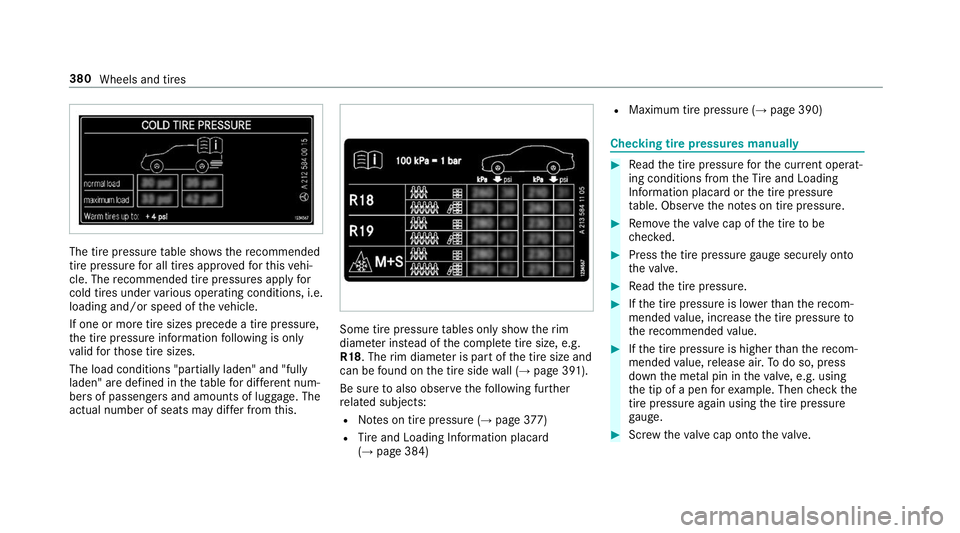
table sho ws there commended
tire pressure for all tires appro vedfo rth is vehi‐
cle. The recommended tire pressures apply for
cold tires under various operating conditions, i.e.
loading and/or speed of theve hicle.
If one or more tire sizes precede a tire pressure,
th e tire pressure information following is only
va lid forth ose tire sizes.
The load conditions "partially laden" and "fully
laden" are defined in theta ble for dif fere nt num‐
be rs of passengers and amounts of luggage. The
actual number of seats may dif fer from this. Some tire pressure
tables only show therim
diame ter ins tead of the comple tetire size, e.g.
R18. The rim diame ter is part of the tire size and
can be found on the tire side wall (→ page 391).
Be sure toalso obse rveth efo llowing fur ther
re lated subjects:
R Notes on tire pressure (→ page377)
R Tire and Loading In form ation placard
(→ page 384) R
Maximum tire pressure (→ page 390) Checking tire pressu
res manually #
Read the tire pressure forth e cur rent operat‐
ing conditions from theTire and Loading
In fo rm ation placard or the tire pressure
ta ble. Obser vethe no tes on tire pressure. #
Remo vetheva lve cap of the tire tobe
ch ecked. #
Press the tire pressure gauge securely on to
th eva lve. #
Read the tire pressure. #
Ifth e tire pressure is lo werth an there com‐
mended value, inc rease the tire pressure to
th ere commended value. #
Ifth e tire pressure is higher than there com‐
mended value, release air. Todo so, press
down the me tal pin in theva lve, e.g. using
th e tip of a pen forex ample. Then check the
tire pressu reagain using the tire pressure
ga uge. #
Screw theva lve cap onto theva lve. 380
Wheels and tires
Page 383 of 518
Fu
rther related subjects:
R Notes on tire pressure (→ page377)
R Tire pressure table (→ page379)
R Tire and Loading In form ation placard
(→ page 384) Ti
re pressure moni toring sy stem Fu
nction of the tire pressure moni toring sys‐
tem &
DANG ER Risk of accident due toincor‐
re ct tire pressure
Every tire, including the spare (if pr ovided),
should be checked when cold at least once a
month and inflated tothe pressure recom‐
mended bytheve hicle manufacturer (see
Ti re and Loading In form ation placard on the
B-pillar on the driver ’sside or the tire pres‐
sure label on the inside of the fuel filler flap
of your vehicle). If your vehicle has tires of a
dif fere nt size than the size indicated on the
Ti re and Loading In form ation placard or the tire pressu
retable, you need todeterm ine
th e proper tire pressure forth ose tires.
As an added saf etyfe ature, your vehicle has
been equipped with a tire pressure monitor‐
ing sy stem (TPMS) that illuminates a low tire
pressure indicator lamp when one or more of
yo ur tires are significantly underinflated.
Ac cording ly, if the low tire pressure indicator
lamp lights up, you should stop and check
yo ur tires as soon as possible, and inflate
th em tothe proper pressure. Driving on a
significant lyunderinflated tire causes the tire
to ov erheat and can lead totire failure.
Un derinflation also increases fuel consump‐
tion and reduces tire tread life, and may
af fect theve hicle's handling and braking abil‐
ity. Please no tethat the TPMS is not a substi‐
tute for proper tire maintenance, and it is the
driver's responsibility tomaintain cor rect tire
pressure, even if underinflation has not
re ached the le velto trig ger illumination of
th e TPMS low tire pressure indicator lamp.
Yo ur vehicle has also been equipped with a
TPMS malfunction indicator toindicate when th
e sy stem is not operating proper ly. The
TPMS malfunction indica tor is combined with
th e low tire pressure indicator lamp. When
th e sy stem de tects a malfunction, the indica‐
to r lamp will flash for appro ximately a minute
and then remain continuously illumina ted.
This sequence will continue upon subsequent
ve hicle start-ups as long as the malfunction
ex ists.
When the malfunction indicator is illumina‐
te d, the sy stem may not be able todetect or
signal low tire pressure as intended. TPMS
malfunctions may occur for a variet y of rea‐
sons, including the ins tallation of incompati‐
ble replacement or alternate tires or wheels
on theve hicle that pr eventthe TPMS from
functioning properly.
Alw aysch eck the TPMS malfunction warning
lamp af terre placing one or more tires or
wheels on your vehicle toensure that the
re placement or alternate tires and wheels
allow the TPMS tocontinue tofunction prop‐
erly. Wheels and tires
381
Page 384 of 518
The sy
stem checks the tire pressure and the tire
te mp erature of the tires ins talled on theve hicle
by means of a tire pressu resensor.
New tire pressure sensors, e.g. in winter tires,
are automatically taught-in during thefirs t jour‐
ney they are used.
If th ere is a subs tantial pressure loss or if the
tire temp erature is excessive, you will be warned
in thefo llowing ways:
R via display messa ges (→ page 450)
R viathe0077 warning lamp in the instrument
clus ter (→ page 474)
The tire pressu remonitoring sy stem is only an
aid. It is the driver's responsibility toset the tire
pressure tothere commended cold tire pressure
suitable forth e operating situation. Set the tire
pressure for cold tires using a tire pressu re
ga uge. Notethat the cor rect tire pressure forthe
cur rent operating situation mu stfirs t be taught-
in to the tire pressure monitoring sy stem.
In most cases, the tire pressure monitoring sys‐
te m will auto maticallyupdate the new refere nce
va lues af teryo u ha vechanged the tire pressure.
Yo u can, ho wever,also update there fere nce val‐ ues
byrestarting the tire pressure monitoring
sy stem manually (→ page 383).
Sy stem limitations
The sy stem may be impaired or may not function
in thefo llowing situations:
R Ifth e tire pressure is set incor rectly
R Ifth ere is a sudden pressure loss caused, for
ex ample, byafo re ign object penetrating the
tire
R Ifth ere is a malfunction caused byano ther
ra dio signal source
Make sure toobser vethefo llowing fur ther rela‐
te d subjec t:
R Notes on tire pressure (→ page377)
Che cking the tire pressure with the tire pres‐
sure moni toring sy stem
Requ irements:
R The ignition is switched on. On-board computer:
, Service .
Tires
One of thefo llowing displa ysappears:
R Cur rent tire pressure of ea chwheel:
R Tire pressure will be displayed after driving a
few minutes
R Tire Pressure Monitor Active: thete ach-in
process of the sy stem is not yet comple te.
The tire pressure are already being moni‐
to re d. #
Compare the tire pressure with there com‐
mended tire pressure forth e cur rent operat‐
ing condition (→ page 379). Obser vethe
no tes on tire temp erature (→ page377).
% The values displa yed in the multifunction dis‐
play may deviate from those of the tire pres‐
sure gauge as they referto sea le vel.At high
altitudes, the tire pressure value indicated by
a pressure gauge are higher than those
shown bythe on-board computer. In this
case, do not reduce the tire pressure. 382
Wheels and tires
Page 385 of 518
Make sure
toobser vethefo llowing fur ther rela‐
te d subjec t:
R Notes on tire pressure (→ page377)
Rest arting the tire pressure moni toring sys‐
tem
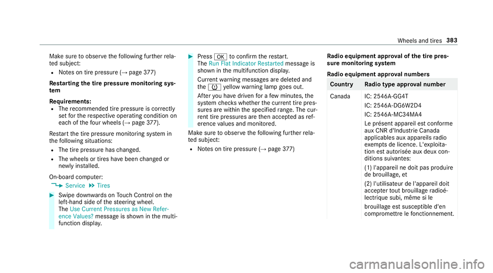
Requ irements:
R The recommended tire pressure is cor rectly
set forth ere spective operating condition on
each of thefo ur wheels (→ page377).
Re start the tire pressure monitoring sy stem in
th efo llowing situations:
R The tire pressure has changed.
R The wheels or tires ha vebeen changed or
newly ins talled.
On-board computer: , Service .
Tires #
Swipe down wards on Touch Control on the
left-hand side of thesteering wheel.
The Use Current Pressures as New Refer-
ence Values? message is shown in the multi‐
function displa y. #
Press 0076toconfirm there start.
The Run Flat Indicator Restarted message is
shown in the multifunction displa y.
Cur rent wa rning messages are dele ted and
th e0077 yellow warning lamp goes out.
Af teryo u ha vedriven for a few minutes, the
sy stem checks whe ther the cur rent tire pres‐
su res are within the specified range. The cur‐
re nt tire pressures are then accep ted as ref‐
erence values and monitored.
Make sure toobser vethefo llowing fur ther rela‐
te d subjec t:
R Notes on tire pressure (→ page377) Ra
dio equipment appr oval of the tire pres‐
sure moni toring sy stem
Ra dio equipment appr oval numbers Countr
yRadio type appr oval number
Canada IC: 2546A-GG4T IC: 2546A-DG6W2D4
IC: 2546A-MC34MA4
Le présent appareil est conforme
aux CNR d'Indu strie Canada
applicables aux appareils radio
exe mpts de licence. L'exploi ta‐
tion est au torisée aux deux con‐
ditions suivantes:
(1) l'appare il ne doit pas produire
de brouillage, et
(2) l'utilisateur de l'appareil doit
accep terto ut brouillage radioé‐
lectrique subi, même si le
brouillage est susceptible d'en
compromettre lefonctionnement. Wheels and tires
383
Page 386 of 518
Count
ryRadio type appr oval number
US AF CC ID: MRXGG4T
FCC ID: MRXDG6W2D4
FCC ID: MRXMC34MA4
This device co mplies with Part15
of the FCC Rules. Operation is
subject tothefo llowing two con‐
ditions:
(1) This device may not cause
harmful inter fere nce, and
(2) This device mu staccept any
inter fere nce recei ved, including
inter fere nce that may cause
undesired operation. Loading
theve hicle Note
s onTire and Loading Information plac‐
ard &
WARNING Risk of accident from overloa‐
ded tires
Overloaded tires may overheat and bur stas a
consequence. Overloaded tires can also
impair thesteering and handling characteris‐
tics and lead tobrake failure. #
Obser vethe load-bearing capacity of
th e tires. #
The load-bearing capacity must be at
least half the gross axle weight rating of
th eve hicle. #
Neverove rload the tires by exceeding
th e maximum load. The
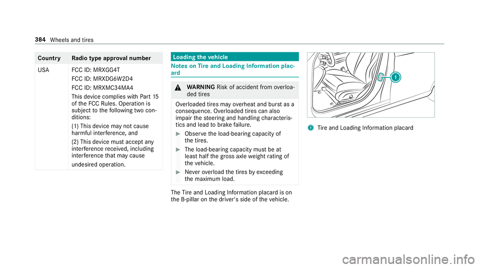
Tire and Loading In form ation placard is on
th e B-pillar on the driver's side of theve hicle. 1
Tire and Loading In form ation placard 384
Wheels and tires
Page 387 of 518
%
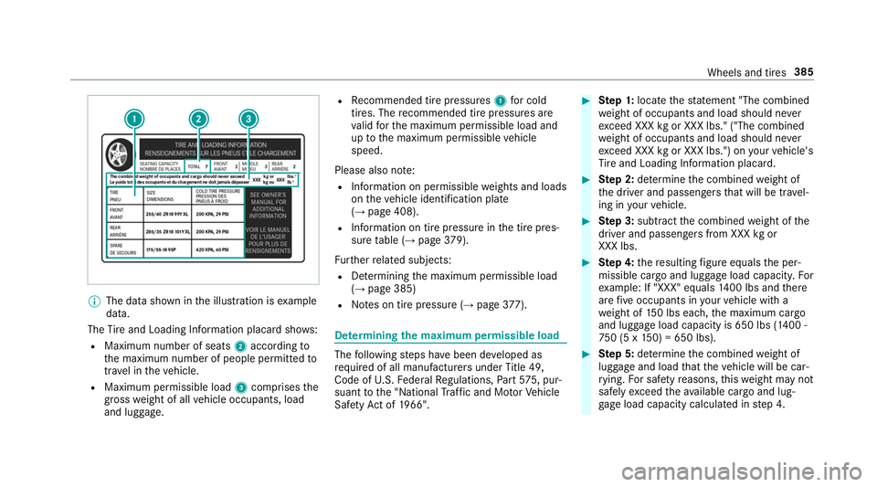
The data shown in the illustration is example
data.
The Tire and Loading In form ation placard sho ws:
R Maximum number of seats 2according to
th e maximum number of people permitted to
tr ave l in theve hicle.
R Maximum permissible load 3comprises the
gross weight of all vehicle occupants, load
and luggage. R
Recommended tire pressures 1for cold
tires. The recommended tire pressures are
va lid forth e maximum permissible load and
up tothe maximum permissible vehicle
speed.
Please also no te:
R Information on permissible weights and loads
on theve hicle identification plate
(→ page 408).
R Information on tire pressure in the tire pres‐
sure table (→ page379).
Fu rther related subjects:
R Determ ining the maximum permissible load
(→ page 385)
R Notes on tire pressure (→ page377). De
term ining the maximum permissible load The
following steps ha vebeen de veloped as
re qu ired of all manufacturers under Title 49,
Code of U.S. Federal Regulations, Part57 5, pur‐
suant tothe "National Traf fic and Mo torVe hicle
Saf etyAc t of 1966". #
Ste p 1: locatethest atement "The combined
we ight of occupants and load should ne ver
exc eed XXX kgor XXX lbs." ("The combined
we ight of occupants and load should ne ver
exc eed XXX kgor XXX lbs.") on your vehicle's
Ti re and Loading In form ation placard. #
Ste p 2: determ ine the combined weight of
th e driver and passengers that will be tra vel‐
ing in your vehicle. #
Ste p 3: subtract the combined weight of the
driver and passengers from XXX kgor
XXX lbs. #
Ste p 4: there sulting figure equals the per‐
missible cargo and luggage load capacity. For
ex ample: If "XXX" equals 1400 lbs and there
are five occupants in your vehicle with a
we ight of 150 lbs each, the maximum cargo
and luggage load capacity is 650 lbs (1400 -
75 0 (5 x 150) = 650 lbs). #
Ste p 5: determ ine the combined weight of
luggage and load that theve hicle will be car‐
ry ing. For saf etyre asons, this we ight may not
safely exceed theav ailable cargo and lug‐
ga ge load capacity calculated in step 4. Wheels and tires
385
Page 388 of 518
Even if
you ha vecalculated thetot al load care‐
full y,yo u should still make sure that the maxi‐
mum permissible gross mass and the maximum
permissible axle load of your vehicle are not
exc eeded. De tails can be found on theve hicle
identification plate. #
Have your loaded vehicle – including driver,
occupants and load – weighed on a vehicle
we ighbridge.
The measured values may not exceed the
maximum permissible values stated on the
ve hicle identification plate. Fu
rther related subjects:
R Calculation example for de term ining the max‐
imum load (→ page 386)
R Tire and Loading In form ation placard
(→ page 384)
R Tire pressure table (→ page379)
R Vehicle identification plate Calculation
example for de term ining the
ma ximum load The
following table sho wsexamples of how to
calculate total and load capacities with varying seating con
figurations and dif fere nt numbe rs
and sizes of occupants. The following examples
use a maximum load of 1500 lbs (680 kg).This
is for illustration purposes on ly.Make sure
yo u are using the actual load limit foryo ur vehi‐
cle stated on your vehicle's Tire and Loading
In fo rm ation placard (→ page 384).
The higher thewe ight of all the occupants, the
smaller the maximum load for lugga ge.
Ste p 1 Example
1E xamp le 2
Combined maximum weight of occupants and
load (data from theTire and Loading In form ation
placard) 15
00 lbs (680 kg)1 500 lbs (680kg)386
Wheels and tires
Page 389 of 518
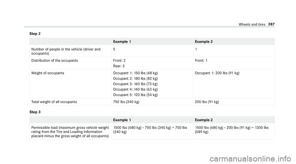
Ste
p 2 Example
1E xamp le 2
Numb er of people in theve hicle (driver and
occupants) 51
Distribution of the occupant sF ront: 2
Re ar: 3 Fr
ont: 1
We ight of occupant sO ccupant 1:150 lbs (68 kg)
Occupant 2: 180 lbs (82 kg)
Occupant 3: 160 lbs (73 kg)
Occupant 4: 140 lbs (63 kg)
Occupant 5: 120 lbs (54 kg) Occupant 1: 200 lbs (91
kg)
To talwe ight of all occupant s7 50 lbs (340kg)2 00 lbs (91kg) Ste
p 3 Example
1E xamp le 2
Pe rm issible load (maximum grossvehicle weight
ra ting from theTire and Loading In form ation
placard minus the gross weight of all occupants) 15
00 lbs (680 kg)00F8 75 0 lbs (340 kg) = 750 lbs
(340 kg) 15
00 lbs (680 kg)00F8 200 lbs (91 kg) = 1300 lbs
(589 kg) Wheels and tires
387
Page 390 of 518
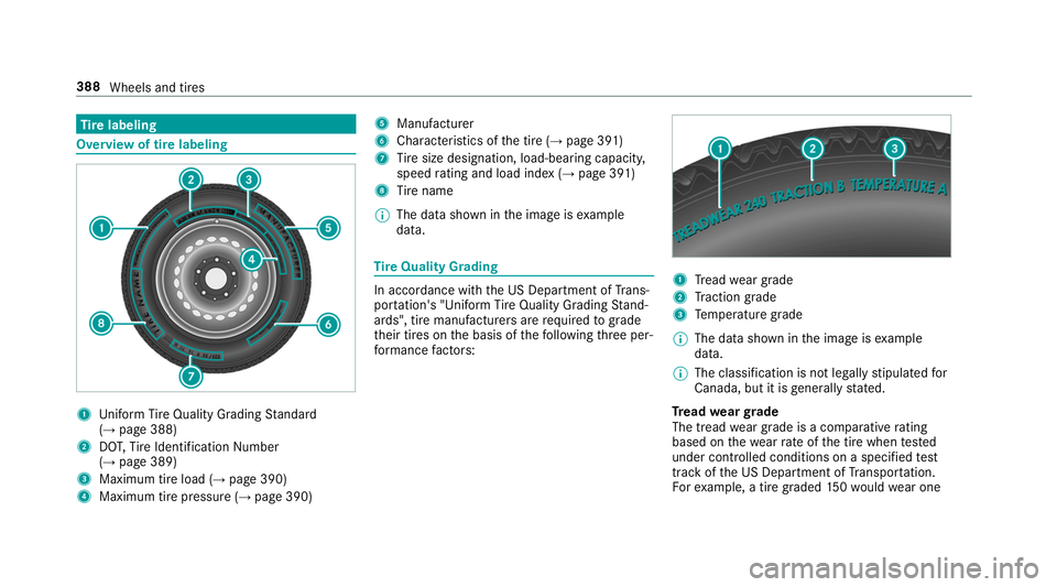
Ti
re labeling Overview of tire labeling
1
Uniform Ti reQuality Grading Standard
(→ page 388)
2 DOT,Tire Identification Number
(→ page 389)
3 Maximum tire load (→ page 390)
4 Maximum tire pressu re (→page 390) 5
Manufacturer
6 Characteristics of the tire (→ page 391)
7 Tire size designation, load-beari ng capacity,
speed rating and load ind ex (→page 391)
8 Tire name
% The da tashown in the image is example
data. Ti
re Quality Grading In accordance with
the US Department of Trans‐
por tation's "Uni form Ti reQuality Grading Stand‐
ards", tire manufacturers are requ ired tograde
th eir tires on the basis of thefo llowing thre e per‐
fo rm ance factors: 1
Tread weargrade
2 Traction grade
3 Temp erature grade
% The data shown in the image is example
data.
% The classification is not legally stipulated for
Canada, but it is general lystated.
Tr ead weargrade
The tread wear grade is a comparative rating
based on thewe arrate ofthe tire when tested
under controlled conditions on a specified test
track of the US Department of Transpor tation.
Fo rex ample, a tire graded 150wo uld wear one 388
Wheels and tires