ignition MERCEDES-BENZ SL ROADSTER 2008 Owners Manual
[x] Cancel search | Manufacturer: MERCEDES-BENZ, Model Year: 2008, Model line: SL ROADSTER, Model: MERCEDES-BENZ SL ROADSTER 2008Pages: 317, PDF Size: 5.35 MB
Page 26 of 317
Cockpit
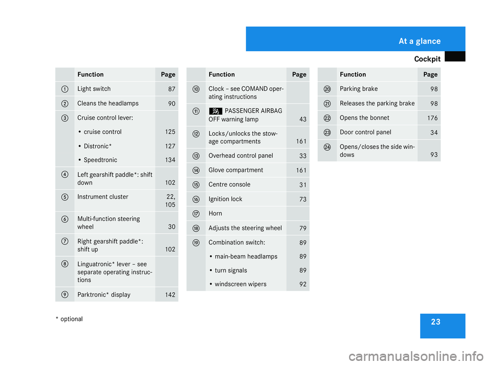
23Function Page
1 Light switch
87
2 Clean
sthe headlamps 90
3 Cruis
econtro llever: •c
ruise control 125
•D
istronic* 127
•S
peedtronic 134
4
Lef
tgearshif tpaddle *: shift
down 102
5 Instrumen
tcluster 22,
105 6 Multi-function steering
wheel
30
7
Right gearshift paddle*:
shift up
102
8
Linguatronic
*lever –see
separat eoperating instruc-
tions 9
Parktronic
*display 142 Function Page
a Clock
–see COMAND oper-
atin ginstructions b 5
PASSENGER AIRBAG
OFF warnin glamp 43
c Locks/unlocks the stow-
age compartments
161
d Overhead control panel
33
e Glove compartment
161
f Centre console
31
g Ignition lock
73
h Horn
j Adjusts the steerin
gwheel 79
k Combination switch:
89
•m
ain-beam headlamps 89
•t
urns ignals 89
•w
indscreen wipers 92 Function Page
l Parking brake
98
m Releases the parking brake
98
n Open
sthe bonnet 176
o Doo
rcontrol panel 34
p Opens/closes the side win-
dows
93At
ag lance
*o ptional
230_AKB; 5; 4, en-GB
bjanott
,V ersion: 2.9.6
2008-04-08T15:09:54+02:00
-Seite 23 Dateiname: 6515_3089_02_buchblock.pdf; preflight
Page 28 of 317
Cockpit
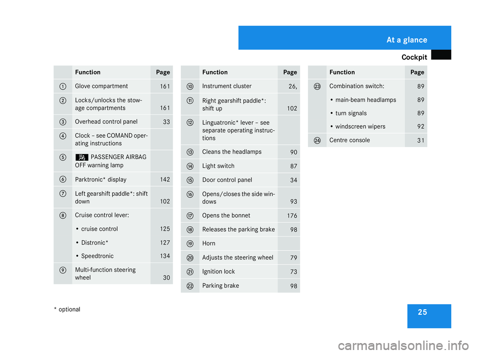
25Function Page
1 Glov
ecom partment 161
2 Locks/unlocks th
estow-
age compartments 161
3 Overhead control panel
33
4 Cloc
k–s ee COMAND oper-
ating instructions 5 5
PASSENGER AIRBAG
OF Fw arning lamp 6
Parktronic* display 142
7
Lef
tgearshif tpaddle *: shift
down 102
8 Cruise control lever:
•c
ruise control 125
•D
istronic* 127
•S
peedtronic 134
9 Multi-function steering
wheel
30 Function Page
a Instrumen
tcluster 26,
b
Right gearshift paddle*:
shift up 102
c
Linguatronic
*lever –see
separat eoperating instruc-
tions d Cleans the headlamps
90
e Light switch
87
f Doo
rcontrol panel 34
g Opens/closes the side win-
dows
93
h Open
sthe bonnet 176
j Releases the parking brake
98
k Horn
l Adjusts the steerin
gwheel 79
m Ignition lock
73
n Parking brake
98 Function Page
o Combination switch:
89
•m
ain-beam headlamps 89
•t
urns ignals 89
•w
indscreen wipers 92
p Centre console
31At
ag lance
*o ptional
230_AKB; 5; 4, en-GB
bjanott
,V ersion: 2.9.6
2008-04-08T15:09:54+02:00
-Seite 25 Dateiname: 6515_3089_02_buchblock.pdf; preflight
Page 44 of 317
Occupant safety
41deceleration forc
ewould normally be high
enough to trigger the systems ,orthey
could be triggered unintentionally. Never
carry out any modifications on the restraint
systems.
Never tamper with electronic components
and their software. SRS (Supplementa
lRestraint System)
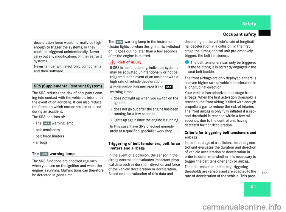
The SRS reduces the risk of occupants com-
ing int ocontact with the vehicle's interior in
the event of an accident. It can also reduce
the forces to which occupants are exposed
during an accident.
The SRS consists of:
R The 1 warning lamp
R belt tensioners
R belt forc elimiters
R airbags
The 1 1 warning lamp The SRS function
sare checked regularly
when you turn on the ignition and when the
engin eisrunning. Malfunctions can therefore
be detected in good time. The
1 warning lamp in the instrument
cluster lights up when the ignition is switched
on. It goes out no later than afew seconds
after the engin eisstarted. G
Risk of injury
If SRS is malfunctioning, individual systems
may be activated unintentionally or not be
triggered in the event of an acciden twith a
high rate of vehicle deceleration.
Am alfunction has occurred if the 1
warning lamp:
R does not light up when you switch on the
ignition
R does not go out after the engin ehas been
running for afew seconds
R lights up again onc ethe engin eisrunning
In this case, have SRS checked immedi-
ately at aqualified specialist workshop.
Triggering of belt tensioners, belt force
limiter sand airbags In the event of
acollision, the sensor in the
airbag control unit evaluates important phys-
ical data such as duration, direction and force
of the vehicle deceleration or acceleration.
Based on the evaluation of this data and depending on the vehicle's rate of longitudi-
nal deceleration in
acollision, in the first
stage the airbag control unit pre-emptively
trigger sthe belt tensioners.
i The belt tensioners can only be triggered
if the belt tongue is correctly engaged in the
seat belt buckle.
The fron tairbags are only deployed if ther eis
an even higher rate of vehicle deceleration in
al ongitudinal direction.
Your vehicle has adaptive, dual stage front
airbags. When the first activation threshold is
reached, the fron tairbag is filled with enough
propellant gas to reduce the risk of injuries.
The fron tairbag is only fully inflated if asec-
ond threshold is reached within afew milli-
seconds, due to the control unit having
detected further deceleration.
Criteria for triggering belt tensioners and
airbags
In the first stage of acollision, the airbag con-
trol unit evaluates the duration and direction
of vehicle acceleration or deceleration in
order to determine whether it is necessary to
trigger the belt tensioner and/or airbag.
The belt tensioner and airbag triggering
thresholds are variable and are adapted to the
rate of deceleration of the vehicle. This proc- Safety
230_AKB
;5;4,en-GB
bjanott, Version:2.9.6
2008-04-08T15:09:54+02:0
0-Seite 41 ZDateiname: 6515_3089_02_buchblock.pdf; preflight
Page 45 of 317
Occupant safety
42
ess is pre-emptive in nature as the airbag
must be deployed during –and not at the end
of –t he collision.
i Airbags are not deployed in all types of
accidents. They are controlled by complex
sensor technology and evaluation logic.
This proces sispre-emptive in nature as
airbag deployment must take place during
the impact and must be adapted to provide
calculated, additional protection for the
vehicle occupants. Not all airbags are
deployed in an accident.
The differen tairbag systems work inde-
pendently of each other .However, each
individual system depends on the type of
acciden tdetermined by the control system
in the first stages of the collision (head-on
collision, side impact ,rear-en dcollision
and overturn) and the extent of the acci-
dent (in particular, the vehicle's rate of
deceleration or acceleration).
The rate of vehicle deceleration or accelera-
tion and the direction of the forc eare basi-
cally determined by:
R the distribution of forces during the colli-
sion
R the collision angle R
the deformation characteristic softhe vehi-
cle
R the characteristic softhe objec twith which
the vehicle has collided, e.g. the other vehi-
cle
Factors which can only be seen and measured
after the collision has taken place do not play
ad ecisive role in the deployment of an airbag,
nor do they provide an indication of it.
The vehicle may be deformed significantly,
e. g. on the bonnet or the wing, without an
airbag being deployed. This happens if only
parts which are relatively easily deformed are
affected and the necessary deceleration does
not occur. Conversely, airbags may be
deployed even though the vehicle suffers only
minor deformations .This is the case if, for
example, very rigid vehicle parts such as lon-
gitudinal body members are affected and suf-
ficien tdeceleration occurs as aresult.
Belt tensioners, belt force limiters The seat belts are fitted with belt tensioners.
!
Do not engage the seat belt tongue in the
buckle on the front-passenger seat if the
seat is not occupied. Otherwise the belt
tensioner could be activated in an emer-
gency. If the seat belt is also equipped with
abelt
forc elimiter, the forc eexerted by the seat
belt on the seat occupant is reduced.
Belt tensioners tighten the seat belts in an
accident, pulling them close against the body.
i Belt tensioners do not correct incorrect
seat position sorincorrectly fastened seat
belts.
Belt tensioners do not pull occupants back
towards the backrest.
The belt forc elimiters are synchronised with
the fron tairbags, which spread the forces
exerted by the belt forc elimiters on the occu-
pant over agreater area.
The seat belts have an automatic comfort-fit
feature. This reduces the retraction forc eof
the seat belts, which results in increased seat
belt comfort.
When the ignition is switched on, the belt ten-
sioner is triggered:
R only if the restraint systems are operational
(the 1 warning lamp lights up after the
ignition is switched on and goes out once
the engin eisrunning)(Y page 41)
R for each three-poin tseat belt in the fron tof
the vehicle when the belt tongue is
engaged in the buckle Safety
230_AKB
;5;4,en-GB
bjanott, Version:2.9.6
2008-04-08T15:09:54+02:0
0-Seite 42 Dateiname: 6515_3089_02_buchblock.pdf; preflight
Page 49 of 317
Occupant safety
46 Roll-over bar
G
Risk of injury
Make sure that the roll-over bar's range of
movemen tisfree to preven tinjuries when
the roll-over bar is extended or retracted.
The roll-over bar extends automatically if sys-
tems detec tthat the vehicle is in danger of
rolling over to the side. You will hear aratch-
etin gnoise when the roll-over bar extends.
You can also extend and retract the roll-over
bar manually with the buttons.
! If the ambient temperature drops below
-5 †, you must extend the roll-over bar
manually. Otherwise, the hydraulics could
be damaged. Extending and retracting the roll-over
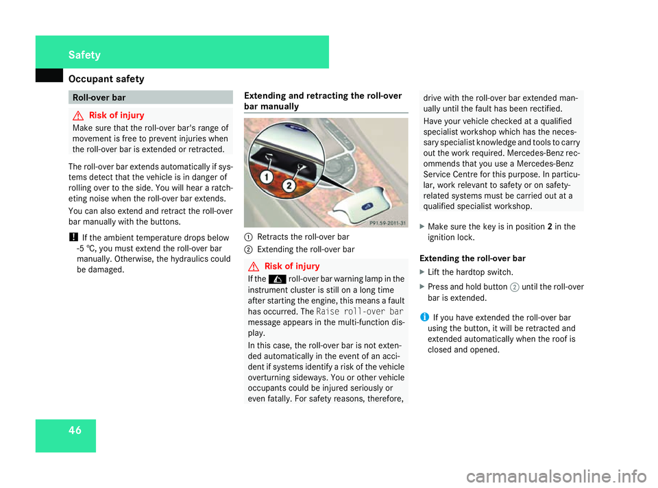
bar manually 1
Retract sthe roll-over bar
2 Extending the roll-over bar G
Risk of injury
If the C roll-over bar warning lamp in the
instrument cluster is still on along time
after starting the engine, this means afault
has occurred. The Raise roll-over bar
message appears in the multi-function dis-
play.
In this case, the roll-over bar is not exten-
ded automatically in the event of an acci-
dent if systems identify arisk of the vehicle
overturnin gsideways. You or other vehicle
occupants could be injured seriously or
even fatally. For safety reasons ,therefore, drive with the roll-over bar extended man-
ually until the fault has been rectified.
Have your vehicle checked at
aqualified
specialist workshop which has the neces-
sary specialist knowledge and tools to carry
out the work required. Mercedes-Benz rec-
ommends that you use aMercedes-Benz
Service Centr efor this purpose. In particu-
lar, work relevant to safety or on safety-
related systems must be carried out at a
qualified specialist workshop.
X Make sure the key is in position 2in the
ignition lock.
Extending the roll-over bar
X Lift the hardtop switch.
X Press and hold button 2until the roll-over
bar is extended.
i If you have extended the roll-over bar
using the button, it will be retracted and
extended automatically when the roof is
closed and opened. Safety
230_AKB
;5;4,en-GB
bjanott, Version:2.9.6
2008-04-08T15:09:54+02:0
0-Seite 46 Dateiname: 6515_3089_02_buchblock.pdf; preflight
Page 53 of 317
Occupant safety
50activ
eeven if the front-passenger fron tair-
bag is disabled. G
Risk of injury
Do not place items of electronic equipment
on the front-passenger seat, e.g.:
R laptops, when switched on
R mobile phones
R cards with transponders, e.g. ski passes
or access cards Signals from electronic equipment can
cause interference in the automatic child
seat recognition sensor system. This can
lead to
asystem malfunction .This may
cause the 5PASSENGER AIRBAG OFF
warning lamp to light up without there
being achild seat with automatic child seat
recognition fitted. This means that the
front-passenger airbag does not deploy
during an accident. It is also possible that the
5 PASSENGER AIRBAG OFF warning
lamp will not light up briefly if you turn the
key in the ignition lock to position 2.
Suitable positioning of the child restraint system Weight categories and ages Child restraint system on the front-passenger seat
Group 0: up to 10 kg;
Up to approximately
9months as recommended
6, 7 Group 0+: up to 13 kg;
Up to approximately 18 months
as recommended
6, 7 Group I:
9to18k g;
Between approximately 8months and 4years as recommended
6, 7 Category II/III: 15 to 36 kg
Between approximately 3½ and 12 years
Universal
7
or as recommended 6
Only use child restraint systems featurin gautomatic child seat recognition.
7 Move the front-passenger seat to the rearmost position. Safety
230_AKB
;5;4,en-GB
bjanott, Version:2.9.6
2008-04-08T15:09:54+02:0
0-Seite 50 Dateiname: 6515_3089_02_buchblock.pdf; preflight
Page 57 of 317
Driving safet
ysystems 54 BAS (Brake Assist)
BAS operates in emergency braking situa-
tions. If yo udepress the brake peda lquickly,
BAS automaticall yboost sthe braking force,
thu sshortening the stopping distance.
X Kee pthe brake peda lfirml yd epresse duntil
the emergency braking situatio niso ver.
ABS prevents the wheels fro mlocking.
Th eb rakes will functio nasusual once you
release the brake pedal. BAS is deactivated. G
Ris
kofa ccident
If BAS ha smalfu nctioned ,the braking sys-
tem remains availabl ewithf ullb rake boost-
ing effect. However, braking force is not
automaticall yincrease dinemergency
braking situations and the stopping dis-
tanc emayincrease. Adaptive brak
elamps
i Adaptive brake lamps ar eonlya vailable in
certai ncountries.
If yo ubrake sharpl yfromas peed of more
tha n50k m/h or if braking is assiste dbyBAS,
the brake lamps flas hrapidly .Inthisw ay,
traffi ctravelling behind yo uiswarne dinan
eve nm oren oticeabl emanner.
After bringing the vehicl etoahalta fter per-
forming such abraking manoeuvre, when the
brake peda lispresse dagain the brake lamps
will once agai nlight up continuously. ESP
®
(Electroni cStability Program)
ESP ®
monitors driving stability and traction,
i.e .p ower transmission between tyres and
the roa dsurface.
If ESP ®
detects tha tthe vehicl eisdeviating
fro mt he directio ndesir ed by the driver ,one
or mor ewheel sarebraked to stabilise the
vehicle. Th eengine outpu tisa lsom odified, if
necessary ,tokeept he vehicl eonthe desired
course withi nphysical limits. ESP ®
assists
the driver when pulling away on we torslip-
pery roads .ESP ®
ca na lsos tabilise the vehi-
cle during braking. When ESP
®
intervenes ,the v warning
lamp flashe sinthe instrumen tcluster. G
Ris
kofa ccident
If the v warning lamp in the instrument
cluste rflashes ,procee dasfollows:
R Do not deactivate ESP ®
under any cir-
cumstances.
R Onl ydepress the accelerator peda lasfar
as necessary when pulling away.
R Adapt your driving style to suit the pre-
vailing roa dand weather conditions.
Th ev ehicl ecould otherwis egointoaskid.
ESP ®
cannot reduc ethe risk of an accident
if yo udrive too fast. ESP ®
cannot override
the laws of physics.
! If:
R the vehicl eisbeing towed with the front
or rea raxler aised
R the parking brake is being tested using a
dynamometer
the ignition must be switched off (ke yin
position 0or 1in the ignition lock). Appli-
catio noft he brakes by ESP ®
could other-
wise destro ythe brake syste monthe front
or rea raxle. Safety
230_AKB; 5; 4, en-GB
bjanott,
Version: 2.9.6 2008-04-08T15:09:54+02:00-Seite 54 Dateiname: 6515_3089_02_buchblock.pdf; preflight
Page 61 of 317
Driving safet
ysystems 58 G
Ris
kofa ccident
If there is afault in the powe rsuppl yort he
vehicle' selectrica lsystem, the SBC TM
brake syste menters emergency mode
becaus eitrequires electrica lpower to
operate. Greater braking force will the nbe
required and the brake peda ltravel and
braking distance will be longer. If neces-
sary ,depress the brake peda lwithm axi-
mu mf orce.
Th eS BCTM
brake syste misautomaticall yacti-
vated if you:
R unlock the vehicl eusing the key or the KEY-
LESS GO *system
R open the driver's or front-passenge rdoor
R switch on the ignition
R press the KEYLESS GO button* on the
selector lever once on vehicles with KEY-
LESS GO
R depress the brake pedal
R release the parking brake
i If yo uactivate the SBC TM
brake system
with the brake pedal, peda lresistanc eis
less tha nnormal the first tim eyou depress
the brake. There is also mor epedal travel tha
nnormal .Pedal travel returns to normal
when yo urelease the brake pedal. Yo umay
fee lthe brake peda lpulsa te when you
release it, and hear asound .Thiss ound,
which is produced by the SBC TM
pump,
cease safter as hort time. G
Ris
kofi njury
If the SBC TM
brake syste misnot deactiva-
ted befor emaintenanc ework—e specially
brake pad/lining replacement —thisc ould
resul tininjury .Ifthe syste misactive, it
carries ou tself- tests, automaticall ybuild-
ing up high pressures in the brake system
for tes tpurposes. Th ebrake calliper pis-
tons ar eforced out, which ca nresul tin
crush injuries .Brake flui dmayescape,
which ca nresul tina cidb urns.
Th eS BCTM
brake syste mmustbed eacti-
vated befor emaintenanc eworkisc arried
out. Yo ucan obtai ninformation on ho wto
deactivate the SBC TM
brake syste matany
Mercedes-Benz Service Centre. G
Ris
kofi njury
Onl yhavet he brake pads/lining sreplaced
and other work on the SBC TM
brake system
carried ou tataqualifie dspecialis twork-
shop. Consult aqualified specialis twork- sho
pwhich ha sthe necessary specialist
knowledg eand tools to carry ou tthe work
required.
Mercedes-Benz recommend sthaty ou use
aM ercedes-Benz Service Centre for this
purpose .Inparticular, work relevant to
safety or on safety-related systems must be
carried ou tataqualifie dspecialis twork-
shop.
Th eS BCTM
brake syste mbrake boos tisa uto-
maticall ydeact ivated:
R after approximately 20 second sifyoulock
the vehicl efromt he outside
R after approximately two minute sifyouturn
the key to position 0in the ignition lock or
remove it fro mthe ignition lock
Tips fo rdrivin gwithS BCTM R
Yo us houl ddownshift ( 1st,2nd or 3rd gear)
when driving on long and steep downhill
gradients .Thisp revents the brakes from
overheating or wearing too quickly.
R Continu edriving for ashort tim eafter sub-
jecting the brakes to aheavy load.This
allows the airflow to coo lthe brakes more
quickly. Safety
*optional
230_AKB; 5; 4, en-GB
bjanott,
Version: 2.9.6 2008-04-08T15:09:54+02:00-Seite 58 Dateiname: 6515_3089_02_buchblock.pdf; preflight
Page 62 of 317
Anti-thef
tsyste ms 59G
Ris
kofa ccident
Make sure tha tyou do not endanger
other roa dusers when applying the
brakes.
R Yo us hould applythe brakes firml yfrom
tim etot imeatah ighv ehicle speedifthe
vehicle' sbrake syste mhasnot been sub-
jected to high load sfor alon gp erio dof
time. This improve sthe gri pofthe brake
pads/linings.
R Yo us hould brakefirml ya fter driving on a
we tors now-covere droads urface before
stopping the engine .The brak ediscs dr yas
the yarewarme dup,thu spreve nting cor-
rosion.
R For safety reasons ,Mercedes-Benz recom-
mends tha tyou onlyusecomponents ,e.g.
brak epads/li nings,which have been spe-
cially approve dbyMercedes-Benz for your
vehicle. Brake pads/linings whic hhaven ot
been approve dfor Mercedes-Benz could
affect your vehicle' sopera ting safety. Anti-theft systems
Immobiliser
Th eimm obiliser prevents your vehicl efrom
being starte dwithout the correct key.
Activating the immobiliser X
With the key: removethe key fro mthe
ignition lock.
X With KEYLES SGO*: pres sthe KEYLESS
GO button on the selector lever.
Th ee ngine switche soff.
Deactivating th eimmob iliser X
Wit hthe key: turn th ekeyto position 2in
th ei gnition lock.
X Wit hKEYLESS GO*: press theKEYLESS
GO butto nontheselecto rlever twic ewith-
out depressin gthe brake.
i The immobilise risalways deactivated
when you start th eengine. ATA (anti-thef
talarm system)
Av isual and audible alar mistriggere difthe
alar msystem is primed and you open:
R ad oor
R ad ooru sin gthe emergency ke yelement
R theb ootlid
R theb onnet
R theg love compartment
R thes towag espac eunder th earmrest
R as towag ecom partmen tintherear
The alar misnotswitched of fevenify ou close
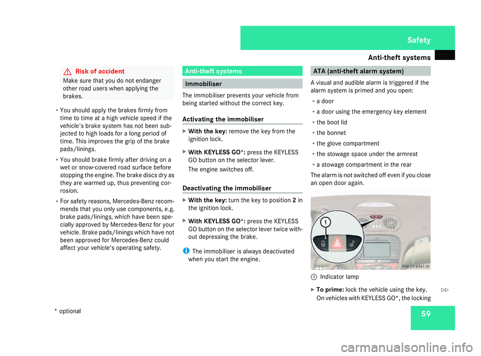
an ope ndoora gain. 1
Indicator lamp
X To prime: lockthe vehicle usin gthe key.
On vehicles wit hKEYLESS GO* ,the locking Safety
*o ptional
230_AKB; 5; 4, en-GB
bjanott
,V ersion: 2.9.6
2008-04-08T15:09:54+02:00
-Seite 59 ZDateiname: 6515_3089_02_buchblock.pdf; preflight
Page 63 of 317
Anti-thef
tsyste ms 60button on the door handle/boo
tlid ca na lso
be used.
Indicato rlamp 1flashes. Th ealarm sys-
tem is primed after approximatel y15sec-
onds.
X To deactivate: unlock the vehicl eusing the
key .Onv ehicle swithK EYLESS GO *, you
can also unlock the vehicle by opening the
door/boot lid.
Switchin goff the alarm X
With the key: insert the key into the igni-
tion lock.
The alarm is switched off.
or
X Press the Œor‹ button on the key.
The alarm is switched off.
X With KEYLES SGO*: grasp the outside
doo rhandle. The key mus tbeo utsid ethe
vehicle.
The alarm is switched off.
or
X Press the KEYLESS GO button on the selec-
tor lever. The key mus tbeinside the vehi-
cle.
The alarm is switched off. Tow-awa
yprotection
An audibl eand visua lalarm is triggered if your
vehicle's angle of inclination is altered while
tow-awa yprotectio nisp rimed .Thish appens
if the vehicle is jacked up on one side, for
example.
Priming tow-awa yprotection X
Lock the vehicle using the key .Onvehicles
with KEYLESS GO*, the locking button on
the doo rhandle/boot li dcan also be used.
Tow-away protectio nisp rimed after
approximately 30 seconds.
To deactivate tow-awa yprotection Whe
nyou unlock your vehicle using the key
or KEYLESS GO *,tow-away protection is
automaticall ydeactivated.
Deactivate tow-away protection manuall yto
prevent afalse alarmify ourv ehicle:
R is being transported
R is being loaded ,e.g.o nto aferry or car
transporter
R is being parked on amovable surface, e.g.
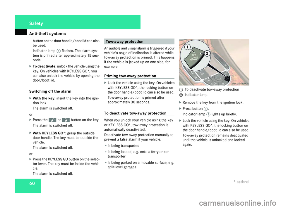
split-level garages 1
To deactivate tow-away protection
2 Indicator lamp
X Remov ethe key fro mthe ignition lock.
X Press button 1.
Indicator lamp 2lights up briefly.
X Loc kthe vehicl eusing the key .Onvehicles
with KEYLESS GO*, the locking button on
the door handle/boo tlid can also be used.
Tow-awa yprotection remains deactivated
unti lthe vehicl eisunlocke dand locked
again. Safety
*optional
230_AKB; 5; 4, en-GB
bjanott,
Version: 2.9.6 2008-04-08T15:09:54+02:00-Seite 60 Dateiname: 6515_3089_02_buchblock.pdf; preflight