clock MERCEDES-BENZ SL ROADSTER 2012 Owners Manual
[x] Cancel search | Manufacturer: MERCEDES-BENZ, Model Year: 2012, Model line: SL ROADSTER, Model: MERCEDES-BENZ SL ROADSTER 2012Pages: 637, PDF Size: 20.68 MB
Page 96 of 637
You could therefore be locked out if:
R the vehicle is being pushed.
R the vehicle is being towed.
R the vehicle is being tested on a dynamom-
eter.
You can also switch the automatic locking
function on and off using the on-board com-
puter (Y page 242). Power closing
Power closing pulls the doors and boot lid into their locks automatically even if they are only
partly closed.
X Power closing feature (doors): push the
door past the first detent position into the
lock.
Power closing will pull the door fully closed.
X To power close the boot lid: lightly push
the boot lid closed.
The power closing function pulls the boot
lid closed. Unlocking the driver's door (emer-
gency key element)
If the vehicle can no longer be unlocked with
the key, use the emergency key element.
If you use the emergency key element to
unlock and open the driver's door, the anti-
theft alarm system will be triggered
(Y page 79).
X Take the emergency key element out of the
key (Y page 86).
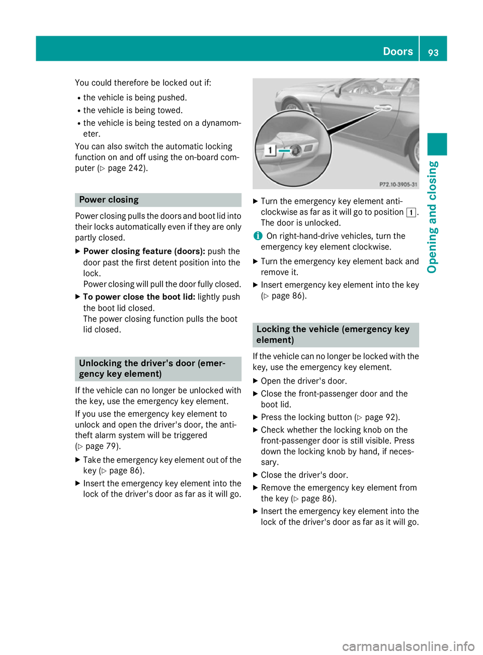
X Insert the emergency key element into the
lock of the driver's door as far as it will go. X
Turn the emergency key element anti-
clockwise as far as it will go to position 1.
The door is unlocked.
i On right-hand-drive vehicles, turn the
emergency key element clockwise.
X Turn the emergency key element back and
remove it.
X Insert emergency key element into the key
(Y page 86). Locking the vehicle (emergency key
element)
If the vehicle can no longer be locked with the key, use the emergency key element.
X Open the driver's door.
X Close the front-passenger door and the
boot lid.
X Press the locking button (Y page 92).
X Check whether the locking knob on the
front-passenger door is still visible. Press
down the locking knob by hand, if neces-
sary.
X Close the driver's door.
X Remove the emergency key element from
the key (Y page 86).
X Insert the emergency key element into the
lock of the driver's door as far as it will go. Doors
93Opening and closing Z
Page 97 of 637
1
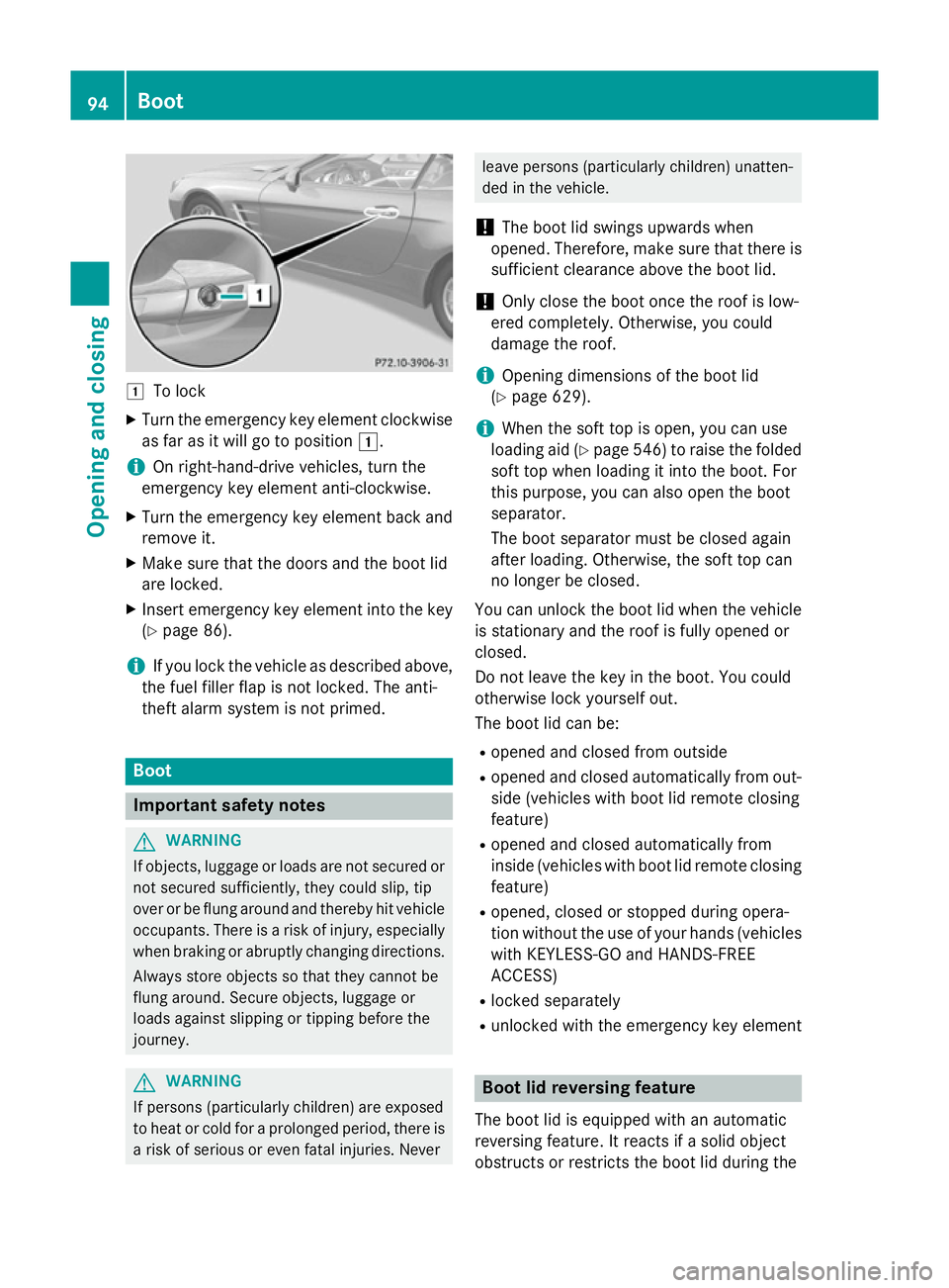
To lock
X Turn the emergency key element clockwise
as far as it will go to position 1.
i On right-hand-drive vehicles, turn the
emergency key element anti-clockwise.
X Turn the emergency key element back and
remove it.
X Make sure that the doors and the boot lid
are locked.
X Insert emergency key element into the key
(Y page 86).
i If you lock the vehicle as described above,
the fuel filler flap is not locked. The anti-
theft alarm system is not primed. Boot
Important safety notes
G
WARNING
If objects, luggage or loads are not secured or not secured sufficiently, they could slip, tip
over or be flung around and thereby hit vehicle
occupants. There is a risk of injury, especially when braking or abruptly changing directions.
Always store objects so that they cannot be
flung around. Secure objects, luggage or
loads against slipping or tipping before the
journey. G
WARNING
If persons (particularly children) are exposed
to heat or cold for a prolonged period, there is a risk of serious or even fatal injuries. Never leave persons (particularly children) unatten-
ded in the vehicle.
! The boot lid swings upwards when
opened. Therefore, make sure that there is sufficient clearance above the boot lid.
! Only close the boot once the roof is low-
ered completely. Otherwise, you could
damage the roof.
i Opening dimensions of the boot lid
(Y page 629).
i When the soft top is open, you can use
loading aid (Y page 546) to raise the folded
soft top when loading it into the boot. For
this purpose, you can also open the boot
separator.
The boot separator must be closed again
after loading. Otherwise, the soft top can
no longer be closed.
You can unlock the boot lid when the vehicle
is stationary and the roof is fully opened or
closed.
Do not leave the key in the boot. You could
otherwise lock yourself out.
The boot lid can be:
R opened and closed from outside
R opened and closed automatically from out-
side (vehicles with boot lid remote closing
feature)
R opened and closed automatically from
inside (vehicles with boot lid remote closing
feature)
R opened, closed or stopped during opera-
tion without the use of your hands (vehicles
with KEYLESS-GO and HANDS-FREE
ACCESS)
R locked separately
R unlocked with the emergency key element Boot lid reversing feature
The boot lid is equipped with an automatic
reversing feature. It reacts if a solid object
obstructs or restricts the boot lid during the 94
BootOpening and closing
Page 101 of 637
Opening/closing automatically from
the inside
Important safety notes G
WARNING
Parts of the body could become trapped dur-
ing automatic closing of the tailgate. In addi-
tion, people may be standing in the closing
area or may enter the closing area, e.g. chil-
dren, during the closing procedure. There is a risk of injury.
Make sure that nobody is in the vicinity of theclosing area during the closing process.
Release the remote operating switch imme-
diately if somebody becomes trapped. To re-
open the tailgate pull on the remote operating
switch. G
WARNING
The boot lid can be automatically opened or
closed even if the key is not in the vehicle. If
children are left unsupervised in the vehicle,
they could activate the functions. There is a
risk of injury.
When leaving the vehicle, always take the key with you and lock the vehicle. Never leave
children unattended in the vehicle.
! The boot lid swings upwards when
opened. Therefore, make sure that there is sufficient clearance above the boot lid.
i Opening dimensions of the boot lid
(Y page 629).
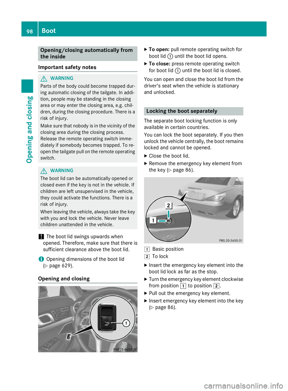
Opening and closing X
To open: pull remote operating switch for
boot lid :until the boot lid opens.
X To close: press remote operating switch
for boot lid :until the boot lid is closed.
You can open and close the boot lid from the
driver's seat when the vehicle is stationary
and unlocked. Locking the boot separately
The separate boot locking function is only
available in certain countries.
You can lock the boot separately. If you then
unlock the vehicle centrally, the boot remains locked and cannot be opened.
X Close the boot lid.
X Remove the emergency key element from
the key (Y page 86). 1
Basic position
2 To lock
X Insert the emergency key element into the
boot lid lock as far as the stop.
X Turn the emergency key element clockwise
from position 1to position 2.
X Pull out the emergency key element.
X Insert emergency key element into the key
(Y page 86). 98
BootOpening and closing
Page 102 of 637
Unlocking the boot (emergency key
element)
! The boot lid swings upwards when
opened. Therefore, make sure that there is sufficient clearance above the boot lid.
If the boot cannot be unlocked with the key or
KEYLESS-GO, use the emergency key ele-
ment.
If you use the emergency key element to
unlock and open the boot lid, the anti-theft
alarm system will be triggered (Y page 79).
X Remove the emergency key element from
the key (Y page 86).
X Insert the emergency key element into the
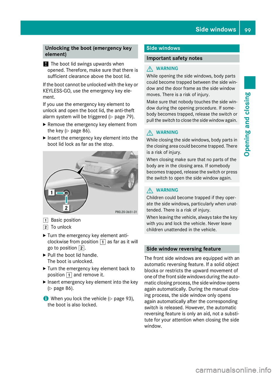
boot lid lock as far as the stop. 1
Basic position
2 To unlock
X Turn the emergency key element anti-
clockwise from position 1as far as it will
go to position 2.
X Pull the boot lid handle.
The boot is unlocked.
X Turn the emergency key element back to
position 1and remove it.
X Insert emergency key element into the key
(Y page 86).
i When you lock the vehicle (Y
page 93),
the boot is also locked. Side windows
Important safety notes
G
WARNING
While opening the side windows, body parts
could become trapped between the side win- dow and the door frame as the side window
moves. There is a risk of injury.
Make sure that nobody touches the side win-
dow during the opening procedure. If some-
body becomes trapped, release the switch or pull the switch to close the side window again. G
WARNING
While closing the side windows, body parts in the closing area could become trapped. There is a risk of injury.
When closing make sure that no parts of the
body are in the closing area. If somebody
becomes trapped, release the switch or press
the switch to open the side window again. G
WARNING
Children could become trapped if they oper-
ate the side windows, particularly when unat- tended. There is a risk of injury.
When leaving the vehicle, always take the key
with you and lock the vehicle. Never leave
children unattended in the vehicle. Side window reversing feature
The front side windows are equipped with an automatic reversing feature. If a solid object
blocks or restricts the upward movement of
one of the front side windows during the auto- matic closing process, the side window opens again automatically. During the manual clos-
ing process, the side window only opens
again automatically after the corresponding
switch is released. However, the automatic
reversing feature is only an aid, not a substi-
tute for your attention when closing the side
window. Side windows
99Opening and closing Z
Page 148 of 637
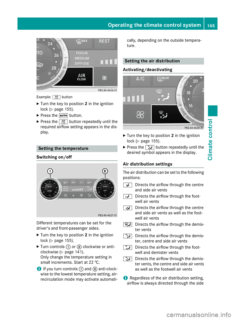
Example:
ñbutton
X Turn the key to position 2in the ignition
lock (Y page 155).
X Press the Ãbutton.
X Press the ñbutton repeatedly until the
required airflow setting appears in the dis-
play. Setting the temperature
Switching on/off Different temperatures can be set for the
driver's and front-passenger sides.
X Turn the key to position 2in the ignition
lock (Y page 155).
X Turn controls :orD clockwise or anti-
clockwise (Y page 141).
Only change the temperature setting in
small increments. Start at 22 †.
i If you turn controls
:and Danti-clock-
wise to the lowest temperature setting, air- recirculation mode may activate automati- cally, depending on the outside tempera-
ture. Setting the air distribution
Activating/deactivating X
Turn the key to position 2in the ignition
lock (Y page 155).
X Press the _button repeatedly until the
desired symbol appears in the display.
Air distribution settings The air distribution can be set to the following
positions:
P Directs the airflow through the centre
and side air vents
O Directs the airflow through the foot-
well air vents
S Directs the airflow through the centre
and side air vents as well as the foot-
well air vents
¯ Directs the airflow through the demis-
ter vents
b Directs the airflow through the demis-
ter, centre and side air vents
a Directs the airflow through the foot-
well and demister vents
_ Directs the airflow through the demis-
ter vents, the centre and side air vents
as well as the footwell air vents
i Regardless of the air distribution setting,
airflow is always directed through the side Operating the climate control system
145Climate control
Page 150 of 637
Air-recirculation mode remains deactiva-
ted.
or
X Press the Ãbutton.
The indicator lamp in the ¬button goes
out. Airflow and air distribution are set to
automatic mode.
or X Turn the temperature controls on the left or
the right on the climate control panel clock- wise or anti-clockwise.
Turn temperature controls :orD clock-
wise or anti-clockwise (Y page 141).
or
X Press the KorI button. Demisting the windows
Windows misted up on the inside X
Activate the ¿cooling with air dehu-
midification function.
X Activate the Ãmode button.
X If the windows continue to mist up, activate
the ¬ "Windscreen demisting" function.
i You should only select this setting until
the windscreen is clear again.
Windows misted up on the outside X
Activate the windscreen wipers.
X Press the _button repeatedly until the
P orO symbol appears in the dis-
play.
i You should only select this setting until
the windscreen is clear again. Rear window heating
General notes The rear window heating has a high current
draw. You should therefore switch it off as
soon as the window is clear. It otherwise
switches off automatically after several
minutes.
If the battery voltage is too low, the rear win-
dow heating may switch off.
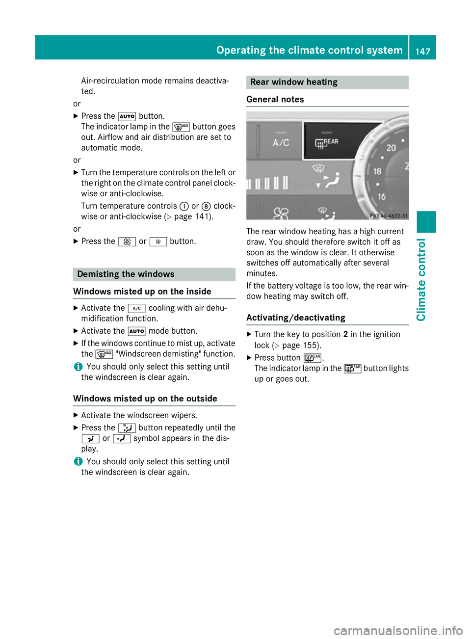
Activating/deactivating X
Turn the key to position 2in the ignition
lock (Y page 155).
X Press button ¤.
The indicator lamp in the ¤button lights
up or goes out. Operating the climate control system
147Climate control
Page 153 of 637
Residual heat is deactivated automatically:
R after approximately 30 minutes
R when the ignition is switched on
R if the battery voltage drops Adjusting the air vents
Important safety notes
G
WARNING
Very hot or very cold air can flow from the air vents. This could result in burns or frostbite in the immediate vicinity of the air vents. There
is a risk of injury.
Make sure that all vehicle occupants always
maintain a sufficient distance to the air out-
lets. If necessary, redirect the airflow to
another area of the vehicle interior. G
WARNING
When AIRSCARF is switched on, very hot air
can flow from the vents in the head restraints. This could result in burns in the immediate
vicinity of the air vents. There is a risk of injury.
Reduce the heater output before it becomes
too hot.
In order to ensure the direct flow of fresh air
through the air vents into the vehicle interior, please observe the following notes:
R keep the air inlet grille on the bonnet and in
the engine compartment on the front-
passenger side free of blockages, such as
ice, snow or leaves.
R never cover the vents or ventilation grilles
in the vehicle interior.
i You can move the adjusters for the air
vents vertically or horizontally to set the
direction of the airflow.
i Optimal climate control function is ach-
ieved by opening the air vents fully and set-
ting the adjusters to the middle position. Setting the centre air vents
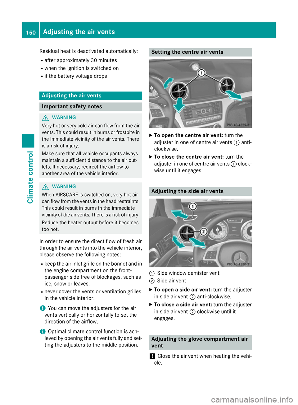
X
To open the centre air vent: turn the
adjuster in one of centre air vents :anti-
clockwise.
X To close the centre air vent: turn the
adjuster in one of centre air vents :clock-
wise until it engages. Adjusting the side air vents
:
Side window demister vent
; Side air vent
X To open a side air vent: turn the adjuster
in side air vent ;anti-clockwise.
X To close a side air vent: turn the adjuster
in side air vent ;clockwise until it
engages. Adjusting the glove compartment air
vent
! Close the air vent when heating the vehi-
cle. 150
Adjusting the air ventsClimate cont
rol
Page 154 of 637
At high outside temperatures, open the air
vent and activate the "cooling with air dehu- midification" function. Otherwise, temper-
ature-sensitive items stored in the glove
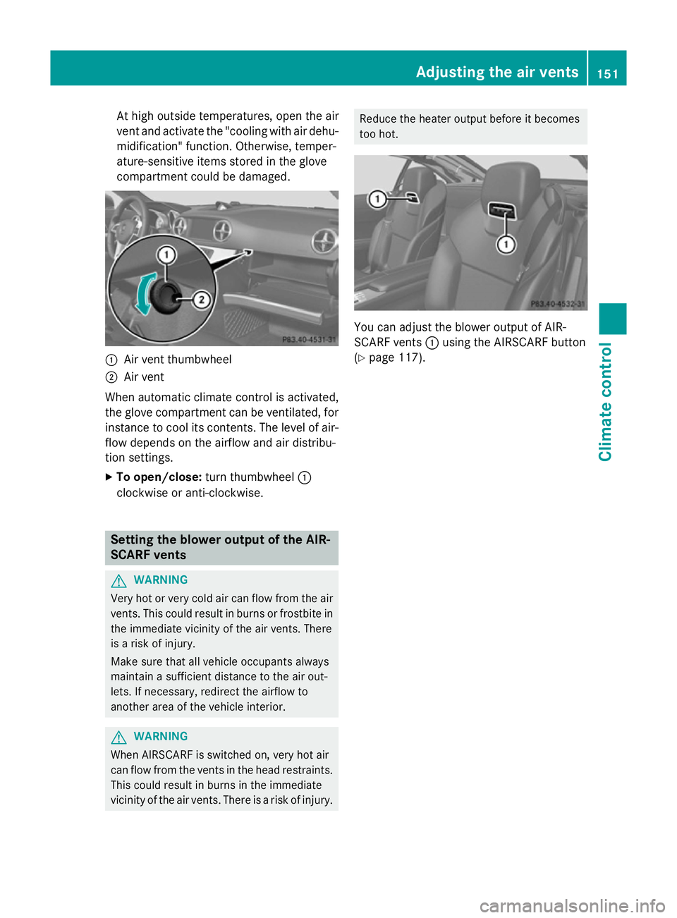
compartment could be damaged. :
Air vent thumbwheel
; Air vent
When automatic climate control is activated,
the glove compartment can be ventilated, for
instance to cool its contents. The level of air-
flow depends on the airflow and air distribu-
tion settings.
X To open/close: turn thumbwheel :
clockwise or anti-clockwise. Setting the blower output of the AIR-
SCARF vents G
WARNING
Very hot or very cold air can flow from the air vents. This could result in burns or frostbite in the immediate vicinity of the air vents. There
is a risk of injury.
Make sure that all vehicle occupants always
maintain a sufficient distance to the air out-
lets. If necessary, redirect the airflow to
another area of the vehicle interior. G
WARNING
When AIRSCARF is switched on, very hot air
can flow from the vents in the head restraints. This could result in burns in the immediate
vicinity of the air vents. There is a risk of injury. Reduce the heater output before it becomes
too hot.
You can adjust the blower output of AIR-
SCARF vents
:using the AIRSCARF button
(Y page 117). Adjusting the air vents
151Climate control Z
Page 177 of 637
fuel. Otherwise, fuel can enter the fuel sys-
tem. Even small amounts of the wrong fuel could result in damage to the fuel system
and the engine. Notify a qualified specialist
workshop and have the fuel tank and fuel
lines drained completely.
! Overfilling the fuel tank could damage the
fuel system.
! Take care not to spill any fuel on painted
surfaces. You could otherwise damage the
paintwork.
! Use a filter when adding fuel from a fuel
can. The fuel lines and/or the diesel injec-
tion system could otherwise be blocked by
particles from the fuel can.
Do not get into the vehicle again during the
refuelling process. Otherwise, electrostatic
charge could build up again.
If you overfill the fuel tank, some fuel may
spray out when you remove the fuel pump
nozzle.
Further information on fuel and fuel quality
(Y page 623). Refuelling
General notes The fuel filler flap is unlocked or locked auto-
matically when you open or close the vehicle
with the key or using KEYLESS-GO.
The position of the 8fuel filler cap is dis-
played in the instrument cluster. The arrow
next to the filling pump indicates the side of
the vehicle. Opening the fuel filler flap :
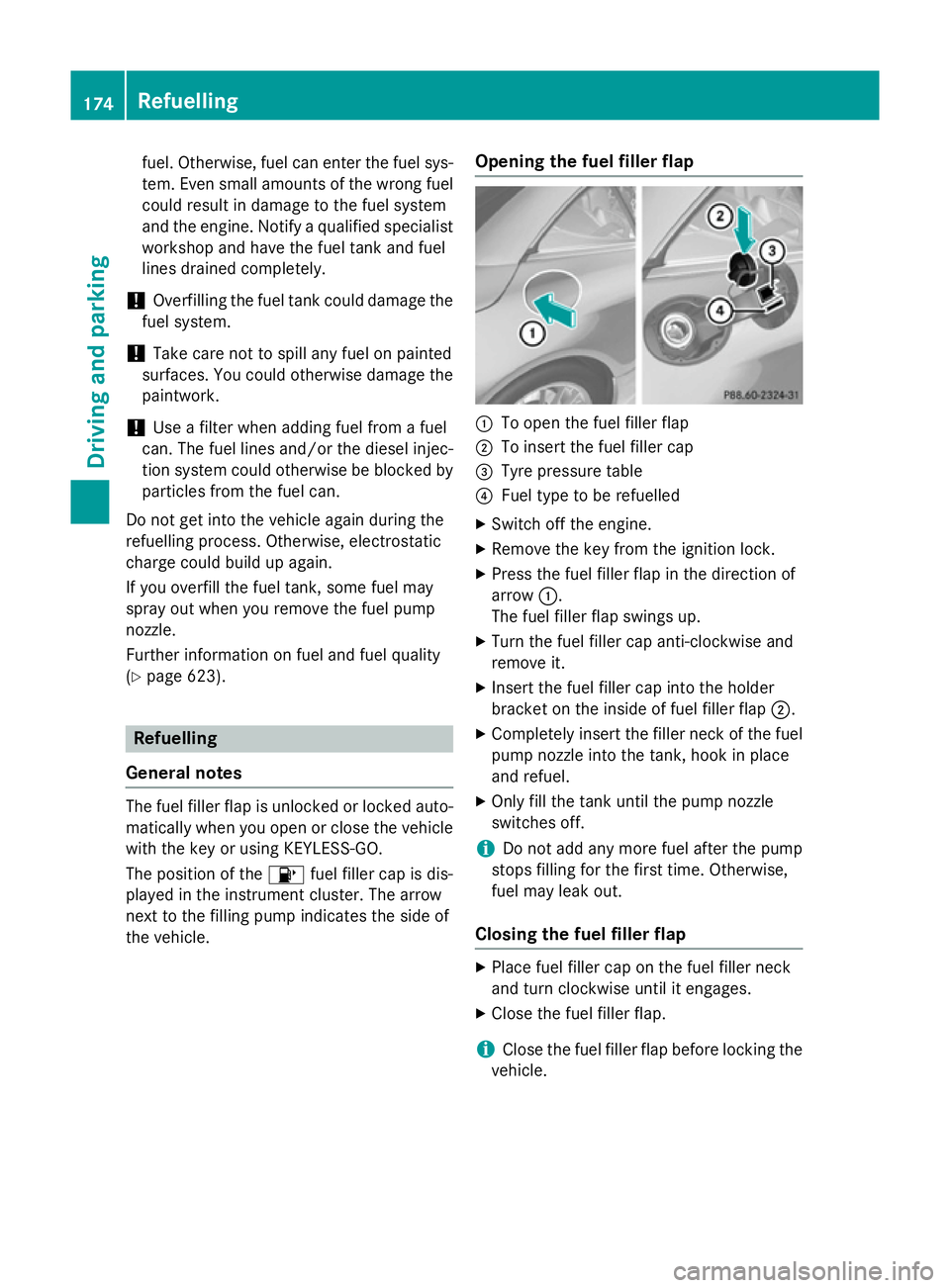
To open the fuel filler flap
; To insert the fuel filler cap
= Tyre pressure table
? Fuel type to be refuelled
X Switch off the engine.
X Remove the key from the ignition lock.
X Press the fuel filler flap in the direction of
arrow :.
The fuel filler flap swings up.
X Turn the fuel filler cap anti-clockwise and
remove it.
X Insert the fuel filler cap into the holder
bracket on the inside of fuel filler flap ;.
X Completely insert the filler neck of the fuel
pump nozzle into the tank, hook in place
and refuel.
X Only fill the tank until the pump nozzle
switches off.
i Do not add any more fuel after the pump
stops filling for the first time. Otherwise,
fuel may leak out.
Closing the fuel filler flap X
Place fuel filler cap on the fuel filler neck
and turn clockwise until it engages.
X Close the fuel filler flap.
i Close the fuel filler flap before locking the
vehicle. 174
RefuellingDriving and parking
Page 201 of 637
R
a system fault occurs
R the power supply is not sufficient
If a fault occurs, then the transmission may
also be shifted into position Pautomatically. RACE START
Important safety notes i
Observe the safety notes for the SPORT
handling mode (Y page 75).
Only activate RACE START on dedicated race circuits.
RACE START enables optimum acceleration
from a standing start. The precondition for
this is a suitable high-grip road surface.
i RACE START is only available for the
SL 63 AMG model.
Activation conditions You can activate RACE START if:
R the doors are closed
R the engine is running and it has reached an
operating temperature of approximately
80 †. This is the case when the engine oil
temperature in the multifunction display
stops flashing.
R SPORT handling mode is activated
(Y page 75)
R the steering wheel is in the straight-ahead
position
R the vehicle is stationary and the brake
pedal is depressed (left foot)
R the transmission is in position D
Activating RACE START X
Depress the brake pedal with your left foot
and keep it depressed.
X Turn the drive program selector clockwise
(Y page 168) until the RSlamp lights up.
The RACE START Confirm: Paddle UP RACE START Confirm: Paddle UP
Cancel: Paddle DOWN
Cancel: Paddle DOWN message appears
in the multifunction display. i
If the activation conditions are no longer
fulfilled, RACE START is cancelled. The mul-
tifunction display shows the RACE START
RACE START
cancelled
cancelled message.
X To cancel: pull the left steering wheel shift
paddle (Y page 169).
or X To confirm: pull the right steering wheel
shift paddle (Y page 169).
The RACE START available Depress RACE START available Depress
accelerator
accelerator message appears in the mul-
tifunction display.
i If you do not depress the accelerator
pedal fully within two seconds, RACE
START is cancelled. The RACE RACESTART
START not
not
possible
possible See
SeeOwner's
Owner's Manual
Manual message
appears in the multifunction display.
X Fully depress the accelerator pedal.
The engine speed increases to at least
3,500 rpm.
The RACE START Release brake to
RACE START Release brake to
start start message appears in the multifunc-
tion display.
i If you do not release the brake pedal
within five seconds, RACE START is cancel- led. The multifunction display shows the
RACE START cancelled
RACE START cancelled message.
X Take your foot off the brake, but keep the
accelerator pedal depressed.
The vehicle pulls away at maximum accel-
eration.
The RACE START active RACE START active appears in the
multifunction display.
RACE START is deactivated when the vehicle
reaches a speed of approximately 50 km/h.
Drive program S+is activated. SPORT han-
dling mode remains activated.
RACE START is deactivated immediately if
you release the accelerator pedal during
RACE START or if any of the activation condi-
tions are no longer fulfilled. The RACE RACESTART
START
not possible See Owner's Manual
not possible See Owner's Manual mes-
sage appears in the multifunction display. 198
Driving systemsDriving and parking