reset MERCEDES-BENZ SLC 2019 Owners Manual
[x] Cancel search | Manufacturer: MERCEDES-BENZ, Model Year: 2019, Model line: SLC, Model: MERCEDES-BENZ SLC 2019Pages: 306, PDF Size: 15 MB
Page 7 of 306
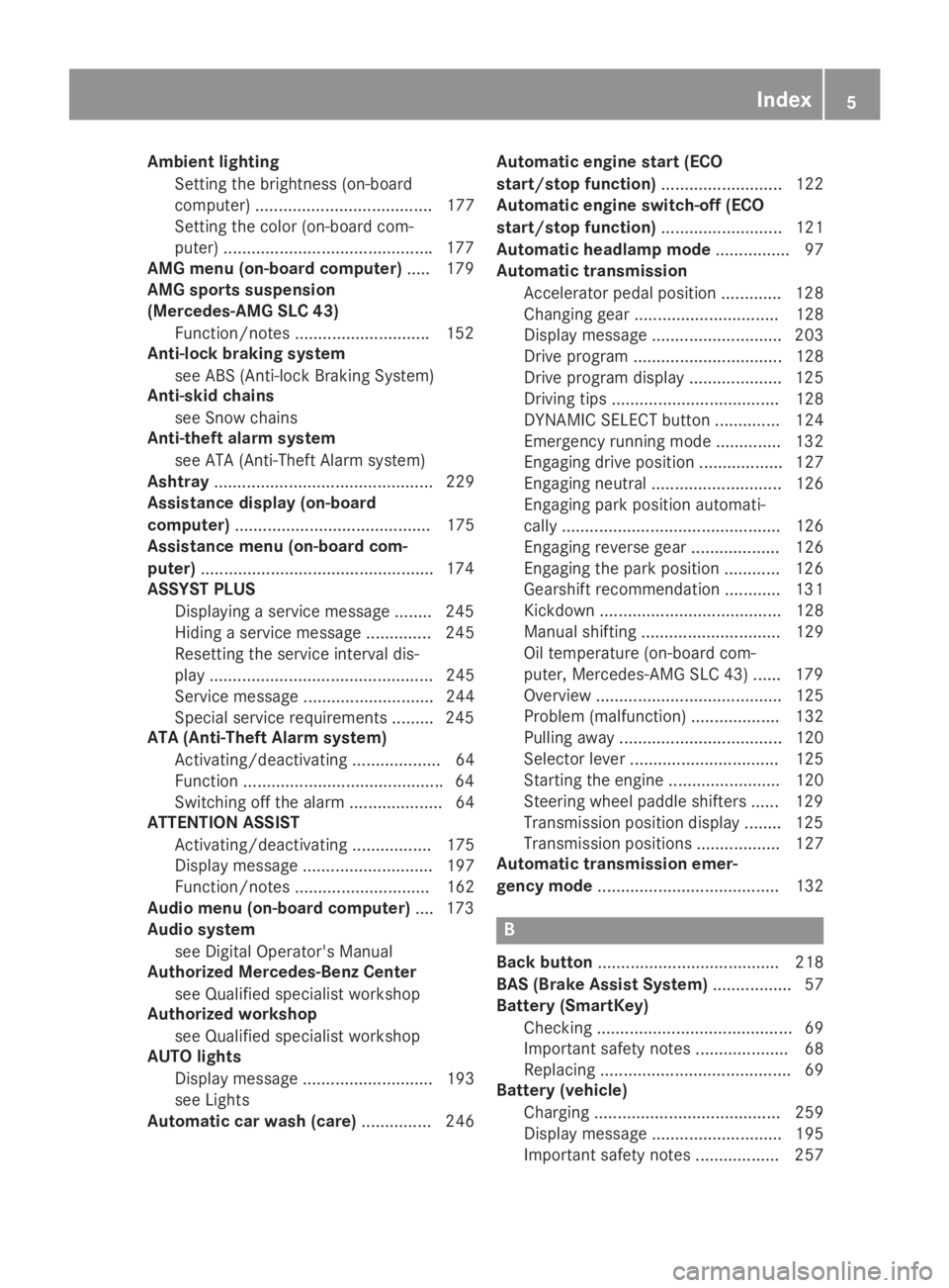
Ambient lighting
Setting the brightness (on-board
computer) ...................................... 177
Setting the color (on-board com-
puter) .............................................177
AMG menu (on-board computer)..... 179
AMG sports suspension
(Mercedes-AMG SLC 43)
Function/notes .............................152
Anti-lock braking system
see ABS (Anti-lock Braking System)
Anti-skid chains
see Snow chains
Anti-theft alarm system
see ATA (Anti-Theft Alarm system)
Ashtray............................................... 229
Assistance display (on-board
computer).......................................... 175
Assistance menu (on-board com-
puter)..................................................174
ASSYST PLUS
Displaying a service message ........245
Hiding a service message .............. 245
Resetting the service interval dis-
play ................................................ 245
Service message ............................ 244
Special service requirements ......... 245
ATA (Anti-Theft Alarm system)
Activating/deactivating ................... 64
Function ...........................................64
Switching off the alarm .................... 64
ATTENTION ASSIST
Activating/deactivating ................. 175
Display message ............................ 197
Function/notes............................. 162
Audio menu (on-board computer).... 173
Audio system
see Digital Operator's Manual
Authorized Mercedes-Benz Center
see Qualified specialist workshop
Authorized workshop
see Qualified specialist workshop
AUTO lights
Display message ............................ 193
see Lights
Automatic car wash (care)............... 246
Automatic engine start (ECO
start/stop function).......................... 122
Automatic engine switch-off (ECO
start/stop function).......................... 121
Automatic headlamp mode................ 97
Automatic transmission
Accelerator pedal position ............. 128
Changing gear ............................... 128
Display message ............................ 203
Drive program ................................ 128
Drive program display .................... 125
Driving tips .................................... 128
DYNAMIC SELECT button .............. 124
Emergency running mode.............. 132
Engaging drive position .................. 127
Engaging neutral ............................ 126
Engaging park position automati-
cally ............................................... 126
Engaging reverse gear ................... 126
Engaging the park position ............ 126
Gearshift recommendation ............ 131
Kickdown ....................................... 128
Manual shifting .............................. 129
Oil temperature (on-board com-
puter, Mercedes-AMG SLC 43) ...... 179
Overview ........................................ 125
Problem (malfunction) ................... 132
Pulling away ................................... 120
Selector lever ................................ 125
Starting the engine ........................ 120
Steering wheel paddle shifters ...... 129
Transmission position display ........ 125
Transmission positions .................. 127
Automatic transmission emer-
gency mode....................................... 132
B
Back button....................................... 218
BAS (Brake Assist System)................. 57
Battery (SmartKey)
Checking .......................................... 69
Important safety notes .................... 68
Replacing ......................................... 69
Battery (vehicle)
Charging ........................................ 259
Display message ............................ 195
Important safety notes .................. 257
Index5
Page 15 of 306
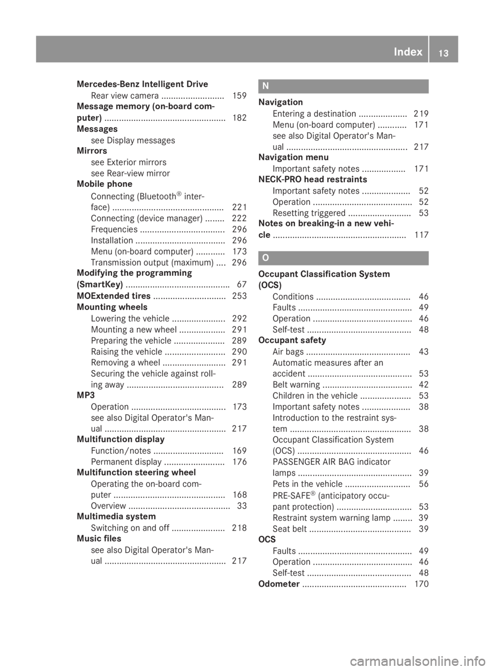
Mercedes-Benz Intelligent Drive
Rear view camera ..........................159
Message memory (on-board com-
puter)..................................................182
Messages
see Display messages
Mirrors
see Exterior mirrors
see Rear-view mirror
Mobile phone
Connecting (Bluetooth®inter-
face) .............................................. 221
Connecting (device manager) ........222
Frequencies ................................... 296
Installation ..................................... 296
Menu (on-board computer) ............ 173
Transmission output (maximum) .... 296
Modifying the programming
(SmartKey)...........................................67
MOExtended tires.............................. 253
Mounting wheels
Lowering the vehicle ...................... 292
Mounting a new wheel ................... 291
Preparing the vehicle .....................289
Raising the vehicle ......................... 290
Removing a wheel .......................... 291
Securing the vehicle against roll-
ing away ........................................ 289
MP3
Operation ....................................... 173
see also Digital Operator's Man-
ual ..................................................217
Multifunction display
Function/notes .............................169
Permanent display ......................... 176
Multifunction steering wheel
Operating the on-board com-
puter .............................................. 168
Overview .......................................... 33
Multimedia system
Switching on and off ......................218
Music files
see also Digital Operator's Man-
ual ..................................................217
N
Navigation
Entering a destination .................... 219
Menu (on-board computer) ............ 171
see also Digital Operator's Man-
ual.................................................. 217
Navigation menu
Important safety notes .................. 171
NECK-PRO head restraints
Important safety notes .................... 52
Operation ......................................... 52
Resetting triggered .......................... 53
Notes on breaking-in a new vehi-
cle....................................................... 117
O
Occupant Classification System
(OCS)
Conditions ....................................... 46
Faults ............................................... 49
Operation ......................................... 46
Self-test ........................................... 48
Occupant safety
Air bags ........................................... 43
Automatic measures after an
accident ........................................... 53
Belt warning ..................................... 42
Children in the vehicle ..................... 53
Important safety notes .................... 38
Introduction to the restraint sys-
tem .................................................. 38
Occupant Classification System
(OCS) ............................................... 46
PASSENGER AIR BAG indicator
lamps ............................................... 39
Pets in the vehicle ........................... 56
PRE-SAFE®(anticipatory occu-
pant protection) ............................... 53
Restraint system warning lamp ........ 39
Seat belt .......................................... 39
OCS
Faults ............................................... 49
Operation ......................................... 46
Self-test ........................................... 48
Odometer........................................... 170
Index13
Page 19 of 306
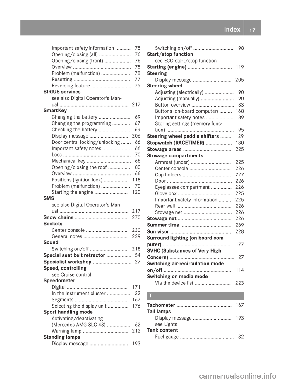
Important safety information ........... 75
Opening/closing (all) ....................... 76
Opening/closing (front) ................... 76
Overview .......................................... 75
Problem (malfunction) .....................78
Resetting .........................................77
Reversing feature .............................75
SIRIUS services
see also Digital Operator's Man-
ual .................................................. 217
SmartKey
Changing the battery ....................... 69
Changing the programming .............67
Checking the battery .......................69
Display message ............................ 206
Door central locking/unlocking ....... 66
Important safety notes.................... 66
Loss ................................................. 70
Mechanical key ................................ 68
Opening/closing the roof................ 80
Overview .......................................... 66
Positions (ignition lock) ................. 118
Problem (malfunction) ..................... 70
Starting the engine ........................ 120
SMS
see also Digital Operator's Man-
ual .................................................. 217
Snow chains...................................... 270
Sockets
Center console .............................. 230
General notes ................................ 229
Sound
Switching on/off........................... 218
Special seat belt retractor.................. 54
Specialist workshop............................ 27
Speed, controlling
see Cruise control
Speedometer
Digital ............................................ 171
In the Instrument cluster ................. 32
Segments ...................................... 167
Selecting the display unit............... 176
Sport handling mode
Activating/deactivating
(Mercedes-AMG SLC 43) ................. 62
Warning lamp ................................. 212
Standing lamps
Display message ............................ 193
Switching on/off.............................. 98
Start/stop function
see ECO start/stop function
Starting (engine)................................ 119
Steering
Display message ............................ 205
Steering wheel
Adjusting (electrically) ..................... 90
Adjusting (manually) ........................ 90
Button overview ............................... 33
Buttons (on-board computer) ......... 168
Important safety notes .................... 89
Storing settings (memory func-
tion) ................................................. 95
Steering wheel paddle shifters........ 129
Stopwatch (RACETIMER)................... 180
Stowage areas................................... 225
Stowage compartments
Armrest (under) ............................. 225
Center console .............................. 226
Cup holders ................................... 227
Door ............................................... 226
Eyeglasses compartment ............... 226
Glove box ....................................... 225
Important safety information ......... 225
Rear wall ........................................ 226
Stowage net ................................... 226
Stowage net....................................... 226
Summer tires..................................... 269
Sun visor............................................ 228
Surround lighting (on-board com-
puter).................................................. 177
SVHC (Substances of Very High
Concern)............................................... 27
Switching air-recirculation mode
on/off................................................. 114
Switching on media mode
Via the device list .......................... 223
T
Tachometer........................................ 167
Tail lamps
Display message ............................ 193
see Lights
Tank content
Fuel gauge ....................................... 32
Index17
Page 21 of 306
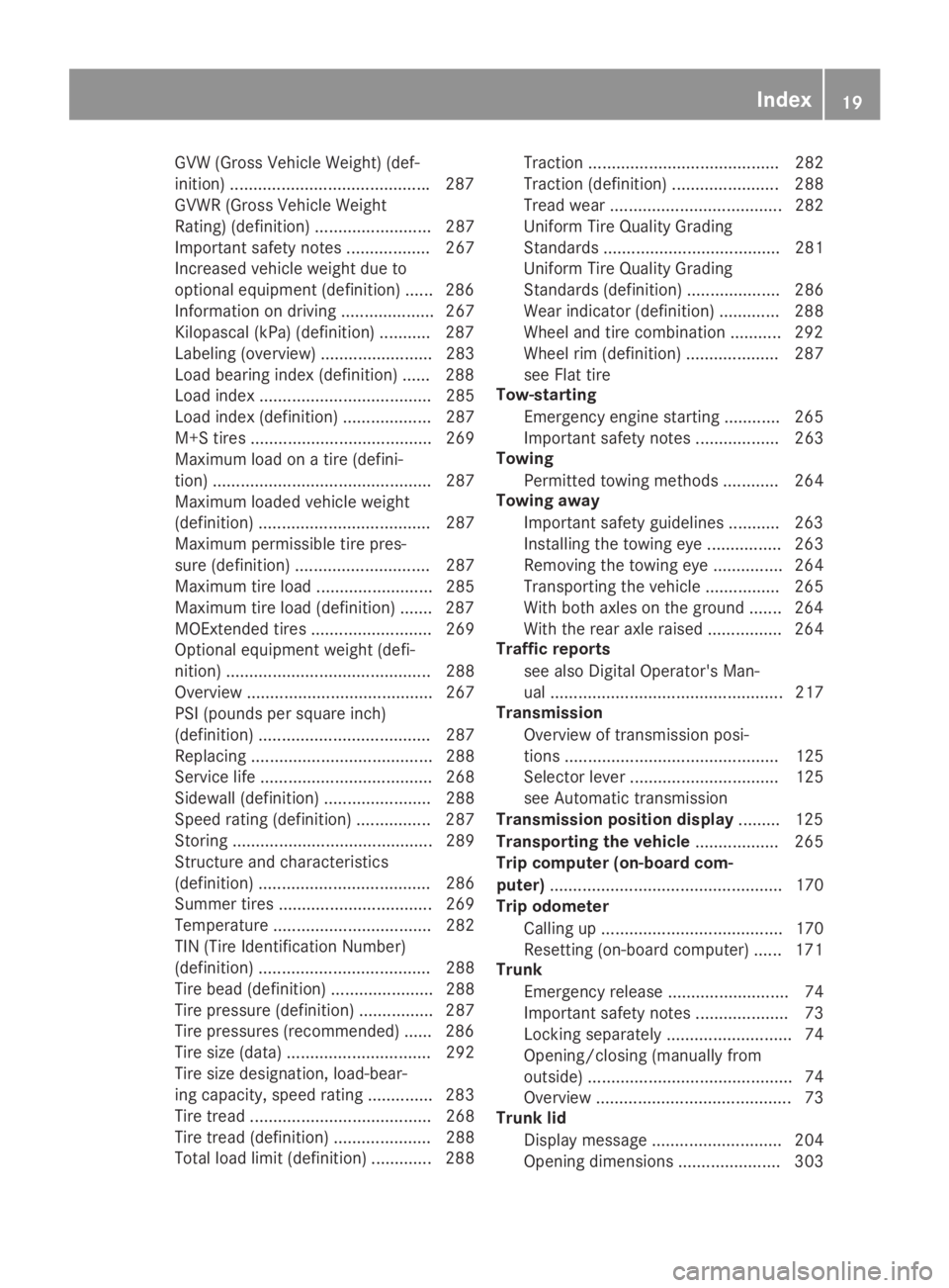
GVW (Gross Vehicle Weight) (def-
inition) ...........................................287
GVWR (Gross Vehicle Weight
Rating) (definition) ......................... 287
Important safety notes .................. 267
Increased vehicle weight due to
optional equipment (definition) ...... 286
Information on driving .................... 267
Kilopascal (kPa) (definition) ........... 287
Labeling (overview)........................ 283
Load bearing index (definition) ...... 288
Load index ..................................... 285
Load index (definition) ................... 287
M+S tires....................................... 269
Maximum load on a tire (defini-
tion) ............................................... 287
Maximum loaded vehicle weight
(definition) ..................................... 287
Maximum permissible tire pres-
sure (definition) ............................. 287
Maximum tire load ......................... 285
Maximum tire load (definition) ....... 287
MOExtended tires.......................... 269
Optional equipment weight (defi-
nition) ............................................ 288
Overview ........................................ 267
PSI (pounds per square inch)
(definition) ..................................... 287
Replacing ....................................... 288
Service life ..................................... 268
Sidewall (definition) ....................... 288
Speed rating (definition) ................ 287
Storing ........................................... 289
Structure and characteristics
(definition) ..................................... 286
Summer tires ................................. 269
Temperature .................................. 282
TIN (Tire Identification Number)
(definition) ..................................... 288
Tire bead (definition) ...................... 288
Tire pressure (definition) ................ 287
Tire pressures (recommended) ...... 286
Tire size (data)............................... 292
Tire size designation, load-bear-
ing capacity, speed rating .............. 283
Tire tread ....................................... 268
Tire tread (definition) ..................... 288
Total load limit (definition) ............. 288
Traction ......................................... 282
Traction (definition) ....................... 288
Tread wear ..................................... 282
Uniform Tire Quality Grading
Standards ...................................... 281
Uniform Tire Quality Grading
Standards (definition) .................... 286
Wear indicator (definition) ............. 288
Wheel and tire combination ........... 292
Wheel rim (definition) .................... 287
see Flat tire
Tow-starting
Emergency engine starting ............ 265
Important safety notes .................. 263
Towing
Permitted towing methods ............ 264
Towing away
Important safety guidelines ........... 263
Installing the towing eye ................ 263
Removing the towing eye ............... 264
Transporting the vehicle ................ 265
With both axles on the ground ....... 264
With the rear axle raised ................ 264
Traffic reports
see also Digital Operator's Man-
ual .................................................. 217
Transmission
Overview of transmission posi-
tions .............................................. 125
Selector lever ................................ 125
see Automatic transmission
Transmission position display......... 125
Transporting the vehicle.................. 265
Trip computer (on-board com-
puter).................................................. 170
Trip odometer
Calling up ....................................... 170
Resetting (on-board computer) ...... 171
Trunk
Emergency release .......................... 74
Important safety notes .................... 73
Locking separately ........................... 74
Opening/closing (manually from
outside) ............................................ 74
Overview .......................................... 73
Trunk lid
Display message ............................ 204
Opening dimensions ...................... 303
Index19
Page 29 of 306
ing interference that may cause undesiredoperation of the device."
Diagnostics connection
The diagnostics connection is used for con-necting diagnostic equipment at a qualifiedspecialist workshop.
GWARNING
If you connect equipment to a diagnostics
connection in the vehicle, it may affect the
operation of vehicle systems. As a result,
the operating safety of the vehicle could be
affected. There is a risk of an accident.
Only connect equipment to a diagnostics
connection in the vehicle, which is approved
for your vehicle by Mercedes-Benz.
GWARNING
Objects in the driver's footwell may restrict
the clearance around the pedals or block a
depressed pedal. This jeopardizes the oper-
ating and road safety of the vehicle. There is
a risk of an accident.
Stow all objects securely in the vehicle so
that they do not get into the driver's foot-
well. When using floormats or carpets, make
sure that they are properly secured so that
they do not slip or obstruct the pedals. Do
not place several floormats or carpets on
top of one another.
!If the engine is switched off and equip-ment on the diagnostics connection is used,the starter battery may discharge.
Connecting equipment to the diagnostics con-nection can lead to emissions monitoringinformation being reset, for example. This maylead to the vehicle failing to meet the require-ments of the next emissions test during themain inspection.
Qualified specialist workshop
An authorized Mercedes-Benz Center is aqualified specialist workshop. It has the neces-sary specialist knowledge, tools and qualifica-tions to correctly carry out the work required
on your vehicle. This is especially the case forwork relevant to safety.
Observe the notes in the Maintenance Book-let.
Always have the following work carried out atan authorized Mercedes-Benz Center:
Rwork relevant to safety
Rservice and maintenance work
Rrepair work
Ralterations, installation work and modifica-tions
Rwork on electronic components
Correct use
If you remove any warning stickers, you or oth-ers could fail to recognize certain dangers.Leave warning stickers in position.
Observe the following information when driv-ing your vehicle:
Rthe safety notes in this manual
Rtechnical data for the vehicle
Rtraffic rules and regulations
Rlaws and safety standards pertaining tomotor vehicles
Information about the REACH regula-
tion
The REACH regulation (Regulation (EC) no.1907/2006, Article 33) lays down an informa-tion obligation for substances of very high con-cern (SVHC).
Daimler AG acts in good faith to avoid usingthese SVHCs and to allow the customer tohandle these substances safely. In accordancewith supplier information and internal productinformation from Daimler AG, SVHCs thataccount for more than 0.1 percent by weightof individual products in this vehicle areknown.
More detailed information can be found at thefollowing addresses:
Rhttp://www.daimler.com/reach(Germanversion)
Rhttp://www.daimler.com/reach/en(English version)
Operating safety27
Introduction
Z
Page 54 of 306
minor deformation. This is the case if, forexample, very rigid vehicle parts such as longi-tudinal body members are hit, and sufficientdeceleration occurs as a result.
If the restraint system control unit detects aside impact or if the vehicle rolls over, theapplicable components of the restraint systemare deployed independently of each otherdepending on the apparent type of accident.
RSide impact air bag on the side of impact,independently of the Emergency TensioningDevice and the use of the seat belt on thedriver's seat
The side impact air bag on the frontpassenger side deploys under the followingconditions:
-the OCS system detects that the frontpassenger seat is occupied or
-the seat belt buckle tongue is engaged inthe belt buckle of the front passengerseat
RHead bag on the side of impact, independ-ently of the use of the seat belt and inde-pendently of whether the front-passengerseat is occupied
REmergency Tensioning Devices, if the sys-tem determines that deployment can offeradditional protection in this situation
RHead bags on the driver's and front-passenger side in certain situations whenthe vehicle rolls over, if the system deter-mines that deployment can offer additionalprotection to that provided by the seat belt
iNot all air bags are deployed in an acci-dent. The different air bag systems workindependently of each other.
How the air bag system works is determinedby the severity of the accident detected,especially the vehicle deceleration or accel-eration and the apparent type of accident:
RHead-on collision
RSide impact
RRollover
NECK-PRO head restraints
Important safety notes
GWARNING
The function of the head restraint may be
impaired if you:
Rattach objects such as coat hangers to
the head restraints, for example
Ruse head restraint covers
If you do so, the head restraints cannot fulfill
their intended protective function in the
event of an accident. In addition, objects
attached to the head restraints could endan-
ger other vehicle occupants. There is an
increased risk of injury.
Do not attach any objects to the head
restraints and do not use head restraint cov-
ers.
Method of operation
NECK-PRO head restraints reduce the likeli-hood of head and chest injuries. The NECK-PRO head restraints on the driver's and front-passenger seats are moved forwards andupwards in the event of a rear-end collision ofa certain severity. This provides better headsupport.
If the NECK-PRO head restraints have beentriggered in an accident, you must reset theNECK-PRO head restraints on the driver’s andfront-passenger seat (Ypage 53). Other-wise, the additional protection will not beavailable in the event of another rear-end colli-sion. You can recognize when NECK-PRO headrestraints have been triggered by the fact thatthey have moved forwards and can no longerbe adjusted.
Mercedes-Benz recommends that you havethe NECK-PRO head restraints checked forfunctionality at a qualified specialist workshopafter a rear-end collision.
52Occupant safety
Safety
Page 55 of 306
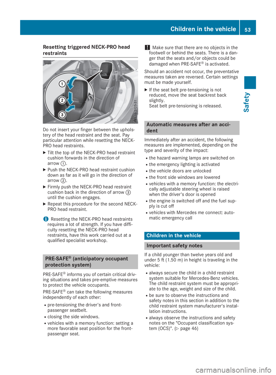
Resetting triggered NECK-PRO head
restraints
Do not insert your finger between the uphols-tery of the head restraint and the seat. Payparticular attention while resetting the NECK-PRO head restraints.
XTilt the top of the NECK-PRO head restraintcushion forwards in the direction ofarrow�C.
XPush the NECK-PRO head restraint cushiondown as far as it will go in the direction ofarrow�D.
XFirmly push the NECK-PRO head restraintcushion back in the direction of arrow�
Page 79 of 306
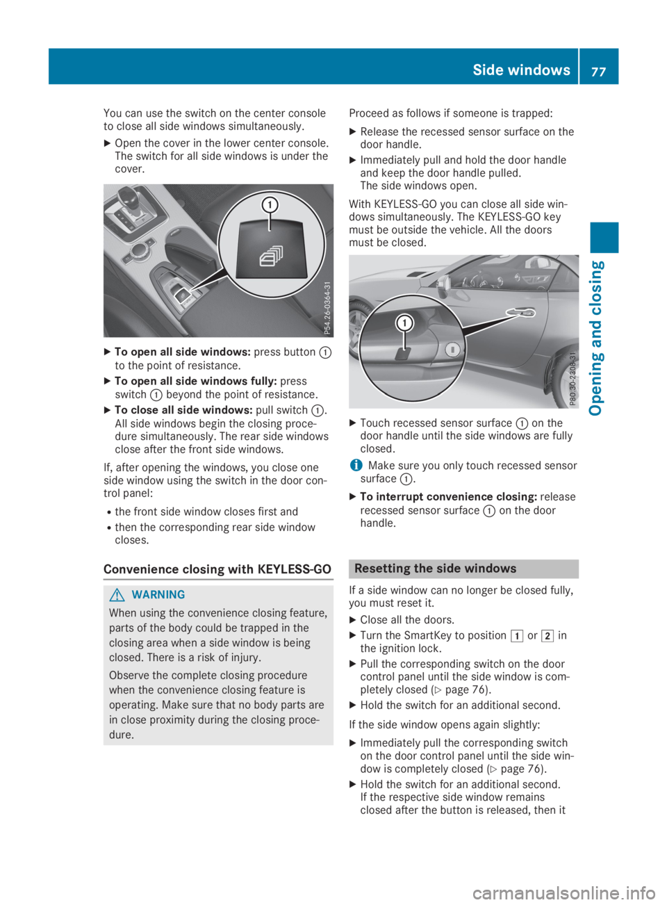
You can use the switch on the center consoleto close all side windows simultaneously.
XOpen the cover in the lower center console.The switch for all side windows is under thecover.
XTo open all side windows:press button�Cto the point of resistance.
XTo open all side windows fully:pressswitch�Cbeyond the point of resistance.
XTo close all side windows:pull switch�C.All side windows begin the closing proce-dure simultaneously. The rear side windowsclose after the front side windows.
If, after opening the windows, you close oneside window using the switch in the door con-trol panel:
Rthe front side window closes first and
Rthen the corresponding rear side windowcloses.
Convenience closing with KEYLESS-GO
GWARNING
When using the convenience closing feature,
parts of the body could be trapped in the
closing area when a side window is being
closed. There is a risk of injury.
Observe the complete closing procedure
when the convenience closing feature is
operating. Make sure that no body parts are
in close proximity during the closing proce-
dure.
Proceed as follows if someone is trapped:
XRelease the recessed sensor surface on thedoor handle.
XImmediately pull and hold the door handleand keep the door handle pulled.The side windows open.
With KEYLESS-GO you can close all side win-dows simultaneously. The KEYLESS-GO keymust be outside the vehicle. All the doorsmust be closed.
XTouch recessed sensor surface�Con thedoor handle until the side windows are fullyclosed.
iMake sure you only touch recessed sensorsurface�C.
XTo interrupt convenience closing:releaserecessed sensor surface�Con the doorhandle.
Resetting the side windows
If a side window can no longer be closed fully,you must reset it.
XClose all the doors.
XTurn the SmartKey to position�Gor�Hinthe ignition lock.
XPull the corresponding switch on the doorcontrol panel until the side window is com-pletely closed (Ypage 76).
XHold the switch for an additional second.
If the side window opens again slightly:
XImmediately pull the corresponding switchon the door control panel until the side win-dow is completely closed (Ypage 76).
XHold the switch for an additional second.If the respective side window remainsclosed after the button is released, then it
Side windows77
Opening and closing
Z
Page 80 of 306
has been set correctly. If this is not thecase, repeat the steps above.
Problems with the side windows
GWARNING
If you close a side window again immediately after it has been blocked or reset, the side win-
dow closes with increased or maximum force. The reversing feature is then not active. Parts of
the body could be trapped in the closing area in the process. This poses an increased risk of
injury or even fatal injury.
Make sure that no parts of the body are in the closing area. To stop the closing process,
release the switch or push the switch again to reopen the side window.
ProblemPossible causes/consequences and�P�PSolutions
A side window cannotbe closed because it isblocked by objects, e.g.leaves in the windowguide.
XRemove the objects.
XClose the side window.
A side window cannotbe closed and you can-not see the cause.
If a side window is obstructed during closing and reopens againslightly:
XImmediately after the window blocks, pull the correspondingswitch again until the side window has closed.The side window is closed with increased force.
If a side window is obstructed again during closing and reopensagain slightly:
XImmediately after the window blocks, pull the correspondingswitch again until the side window has closed.The side window is closed without the automatic reversing fea-ture.
The side windows can-not be opened or closedusing the convenienceopening/closing fea-ture.
The SmartKey battery is discharged or nearly discharged.
XCheck the SmartKey battery (Ypage 69) and replace it if neces-sary (Ypage 69).
Roof
Important safety notes
GWARNING
If you do not fully open/close the soft top,
the soft-top hydraulics depressurize after a
short time. This causes the soft top to lower
unexpectedly and may cause you or others
to be trapped. There is a risk of injury.
Always open or close the soft top com-
pletely.
GWARNING
Closing the roof manually is a complicated
and technically demanding procedure, which
requires a lot of strength. You or others can
become trapped. There is a risk of injury.
78Roof
Opening and closing
Page 97 of 306
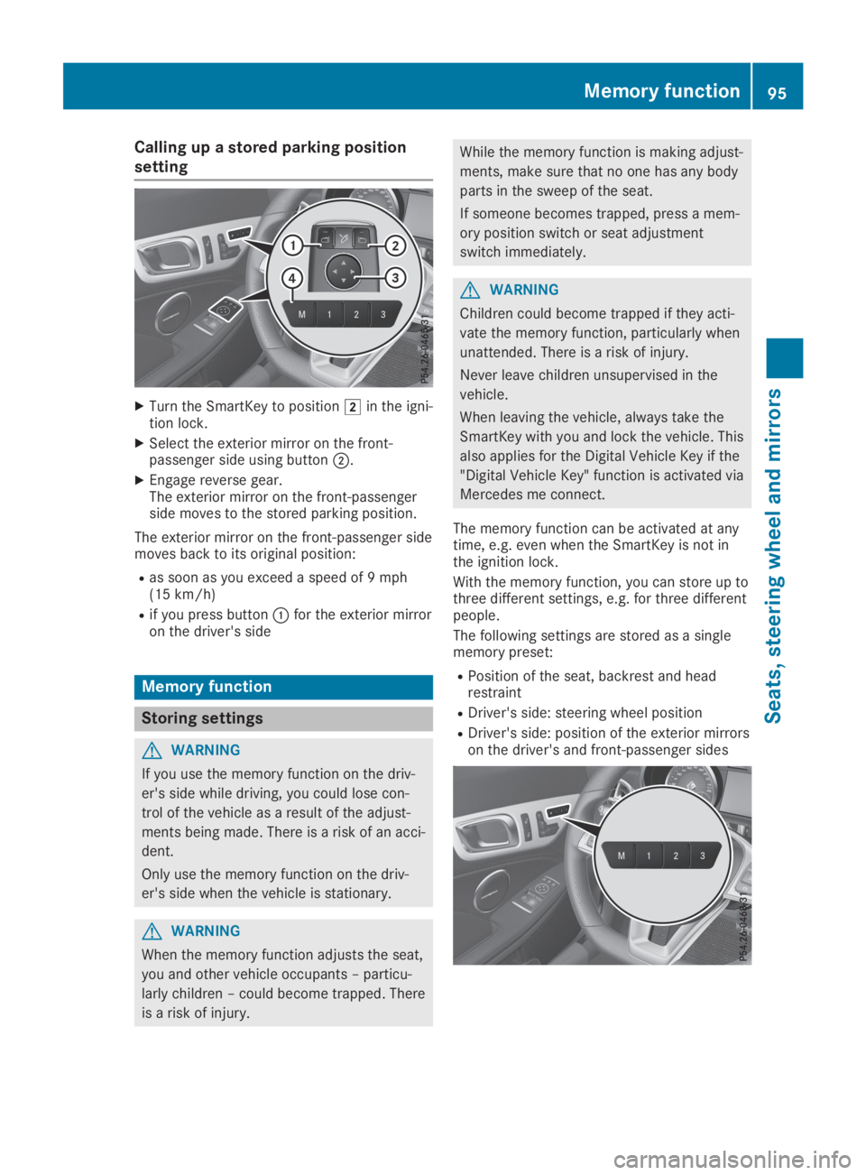
Calling up a stored parking position
setting
XTurn the SmartKey to position�Hin the igni-tion lock.
XSelect the exterior mirror on the front-passenger side using button�D.
XEngage reverse gear.The exterior mirror on the front-passengerside moves to the stored parking position.
The exterior mirror on the front-passenger sidemoves back to its original position:
Ras soon as you exceed a speed of 9 mph(15 km/h)
Rif you press button�Cfor the exterior mirroron the driver's side
Memory function
Storing settings
GWARNING
If you use the memory function on the driv-
er's side while driving, you could lose con-
trol of the vehicle as a result of the adjust-
ments being made. There is a risk of an acci-
dent.
Only use the memory function on the driv-
er's side when the vehicle is stationary.
GWARNING
When the memory function adjusts the seat,
you and other vehicle occupants – particu-
larly children – could become trapped. There
is a risk of injury.
While the memory function is making adjust-
ments, make sure that no one has any body
parts in the sweep of the seat.
If someone becomes trapped, press a mem-
ory position switch or seat adjustment
switch immediately.
GWARNING
Children could become trapped if they acti-
vate the memory function, particularly when
unattended. There is a risk of injury.
Never leave children unsupervised in the
vehicle.
When leaving the vehicle, always take the
SmartKey with you and lock the vehicle. This
also applies for the Digital Vehicle Key if the
"Digital Vehicle Key" function is activated via
Mercedes me connect.
The memory function can be activated at anytime, e.g. even when the SmartKey is not inthe ignition lock.
With the memory function, you can store up tothree different settings, e.g. for three differentpeople.
The following settings are stored as a singlememory preset:
RPosition of the seat, backrest and headrestraint
RDriver's side: steering wheel position
RDriver's side: position of the exterior mirrorson the driver's and front-passenger sides
Memory function95
Seats, steering wheel and mirrors
Z