coolant MERCEDES-BENZ SLK ROADSTER 2012 Owners Manual
[x] Cancel search | Manufacturer: MERCEDES-BENZ, Model Year: 2012, Model line: SLK ROADSTER, Model: MERCEDES-BENZ SLK ROADSTER 2012Pages: 321, PDF Size: 6.9 MB
Page 14 of 321
Opening/closing the garage door
..245
Programming (button in the rear-
view mirror) ................................... 243
Gear indicator (on-board com-
puter) ................................................. .195
Gear or selector lever (cleaning
instructions) ...................................... 258
Gearshift program SETUP (on-board computer) ..........196
Genuine Mercedes-Benz parts .........300
Glove compartment ..........................236 H
Handbrake see Parking brake
Hazard warning lamps ......................103
Headbag Display message ............................ 208
Operation ........................................ .43
Headlamp
Cleaning system (function) ............102
Headlamp cleaning system
Notes ............................................. 309
Headlamps
Misting up ...................................... 105
Topping up the cleaning system ....252
see Automatic headlamp mode
Head level heating (AIRSCARF) ..........91
Head restraints Adjusting ......................................... 90
see NECK-PR Ohead restraints
Heating
see Climate control
High-pressure cleaners ....................254
Hill start assist .................................. 130
HOLD function Display message ............................ 213
Function/notes ............................. 165 I
Ignition lock see Key positions
Immobiliser .......................................... 61
Indicator and warning lamps Coolant .......................................... 231
DISTRONI CPLUS ........................... 233Engine diagnostics
.........................231
Fuel tank ........................................ 231
SPORT handling mode ...................229
Indicator lamps
Display message ............................ 208
see Warning and indicator lamps
Indicators
see Turn signals
Insectp rotection on the radiator ....250
Instrument cluster Overview .......................................... 28
Settings ......................................... 190
Warning and indicator lamps ...........30
Instrument cluster lighting ..............178
Instrument lighting see Instrument cluster lighting
Intelligen tLight System
Activating/deactivatin g................. 191
Display message ............................ 210
Overview ........................................ 104
Setting the dipped-bea mhead-
lamps for driving on the right/left .192
Interior lighting ................................. 105
Automatic control system ..............105
Delayed switch-off (on-board
computer) ...................................... 193
Emergency lighting ........................106
Manual control ............................... 106
Overview ........................................ 105
Reading lamp ................................. 105
Setting the ambient lighting
brightness (on-board computer) ....192
Interior motion sensor ........................62 J
Jack Storage location ............................ 261
Using ............................................. 268
Jump start (engine)
see Jump starting (engine)
Jump starting (engine) ......................277 K
Key Changing the battery .......................69
Checking the battery .......................69 Index
11
Page 18 of 321
Refuelling
Fuelgauge ....................................... 28
Important safety notes ..................142
Refuelling proces s......................... 143
see Fuel
Releasing the parking loc kman-
ually (automatic transmission) ........142
Remote control Garage door opene r....................... 243
Programming (garage door
opener) .......................................... 243
Reserve (fuel tank)
see Fuel
Reserve fuel
Display message ............................ 212
Warning lamp ................................. 231
Residual heat (climate control) ........122
Restraint system see SRS (Supplemental Restraint
System)
Rev counter ........................................ 179
Reverse gear Engaging (automatic transmis-
sion) ............................................... 137
Engaging (manual transmission) ....136
Reversible floor (boot) ......................238
Reversing lamp Changing bulbs .............................. 109
Reversing lamps
Display message ............................ 210
Roof
Display message ............................ 221
Important safety notes ....................78
Opening/closing (with key) .............. 80
Opening/closing (with roof
switch) ............................................. 79
Problem (malfunction) .....................82
Relocking ......................................... 80
Roof carrier ........................................ 238
Roof lining and carpets (cleaning
instructions) ...................................... 258
Roof switch .......................................... 79
Route (navigation) see Route guidance (navigation)
Route guidance (navigation) ............184 S
Safety Childre ninthe vehicle ..................... 47
Child restraint systems ....................47
Safety systems
see Driving safety systems
Seat belt
Adjusting the driver's and front-
passenger sea tbelt ......................... 46
Belt force limiter .............................. 46
Belt tensione r.................................. 46
Cleaning ......................................... 258
Fastening ......................................... 45
Important safety guidelines .............44
Releasing ......................................... 46
Switching belt adjustment on/off
(on-board computer) ......................194
Warning lamp ................................. 224
Warning lamp (function) ................... 46
Seats
Adjusting (electrically). ....................90
Adjusting (manually )........................ 89
Adjusting the 4-way lumba rsup-
por t.................................................. 90
Adjusting the head restraint ............90
Cleaning the cover .........................258
Correct driver's seat position ........... 88
Important safety notes ....................89
Seat heating problem ......................91
Storing settings (memory func-
tion) ................................................. 96
Switching AIRSCARF on/off ............91
Switching sea theating on/off .........90
Sensors (cleaning instructions) .......257
Service see ASSYST PLUS service interval
display
Service Centre
see Qualified specialist workshop
Service menu (on-board computer) .190
Service products Brake fluid ..................................... 308
Coolant (engine) ............................ 308
Engine oil ....................................... 307
Fuel ................................................ 303
Important safety notes ..................303
Washer fluid .................................. .309 Index
15
Page 20 of 321
Summer opening
see Convenience opening feature
Summer tyres .................................... 288
Sun visor ............................................ 240
Supplement Restraint System see SRS (Supplemental Restraint
System)
Surround lighting (on-board com-
puter) ................................................. .192
Switching off the alarm (ATA) ............61 T
Tail lamps Display message ............................ 209
see Lights
Tank
see Fuel tank
Technical data
Notes ............................................. 300
Tyres/wheels ................................. 295
Vehicle data ................................... 310
Telephone
Accepting acall............................. 188
Display message ............................ 221
Menu (on-board computer) ............187
Number from the phone book ....... .188
Redialling ....................................... 188
Rejecting/ending acall................. 188
Telephone compartment ................237
Temperature
Coolant .......................................... 178
Coolant (on-board computer) ......... 195
Engine oil (on-board computer) ...... 195
Outside temperature ..................... .179
Setting (climate control) ................118
TEMPOMAT
Function/notes ............................. 151
Theft-deterrent system
ATA (Anti-Theft Alarm system) .........61
Immobiliser ...................................... 61
Time
see Separate Owner' smanual
Timing (RACETIMER) .........................196
TIREFIT kit .......................................... 263
Total distance recorder ....................183
Tow-away protection ..........................62Towing
Important safety notes ..................278
With the rear axle raised ................280
Towing away
Fitting the towing eye. ...................279
Removing the towing eye. ..............280
With both axles on the ground .......280
Tow-starting
Emergency engine starting ............281
Fitting the towing eye. ...................279
Important safety notes ..................278
Removing the towing eye. ..............280
Transmission
see Automatic transmission
see Manual transmission
Transporting the vehicle ..................281
Trim pieces (cleaning instructions) .258
Trip computer (on-board com-
puter) ................................................. .183
Trip meter Calling up ....................................... 183
Resetting (on-board computer) ......184
Trip odometer
see Trip meter
Turn signals
Changing bulbs (front) ...................108
Switching on/off ........................... 103
Two-way radio
Frequencies ................................... 301
Installatio n..................................... 301
Transmission output (maximum) .... 301
Type identification plate
see Vehicle identification plate
Tyre pressure
Calling up (on-board computer) .....292
Display message ............................ 217
Not reached (TIREFIT) ....................265
Pressure loss warning ....................291
Reached (TIREFIT) ..........................265
Recommended ............................... 289
Tyre pressure monitor
Function/notes ............................. 292
Restarting ...................................... 293
Warning lamp ................................. 233
Tyres
Checking ........................................ 287
Direction of rotatio n...................... 295 Index
17
Page 31 of 321
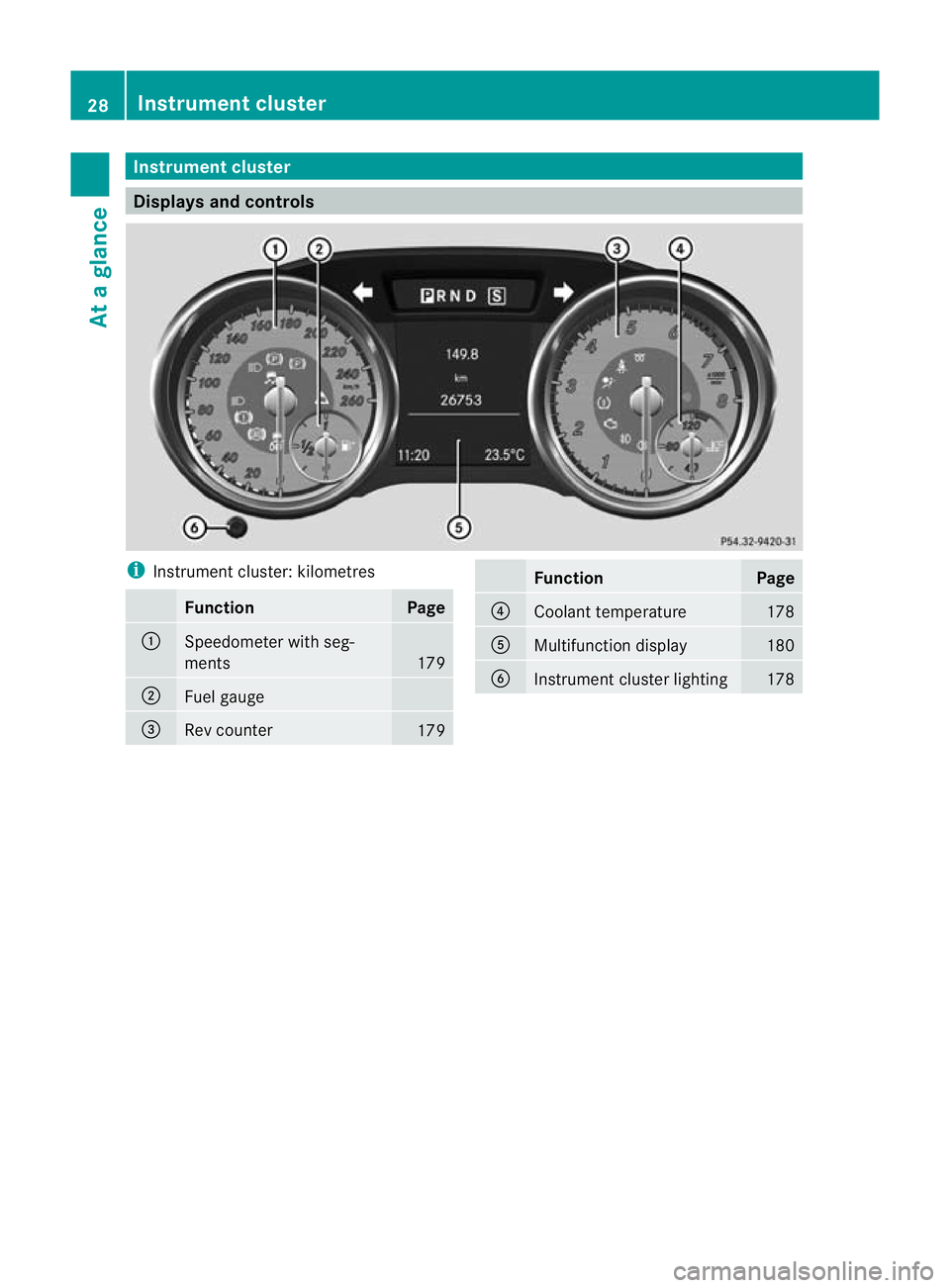
Instrumen
tcluster Displays and controls
i
Instrument cluster: kilometres Function Page
:
Speedometer with seg-
ments
179
;
Fuel gauge
=
Rev counter
179 Function Page
?
Coolant temperature 178
A
Multifunction display 180
B
Instrument cluster lighting 17828
Instrument clusterAt a glance
Page 32 of 321
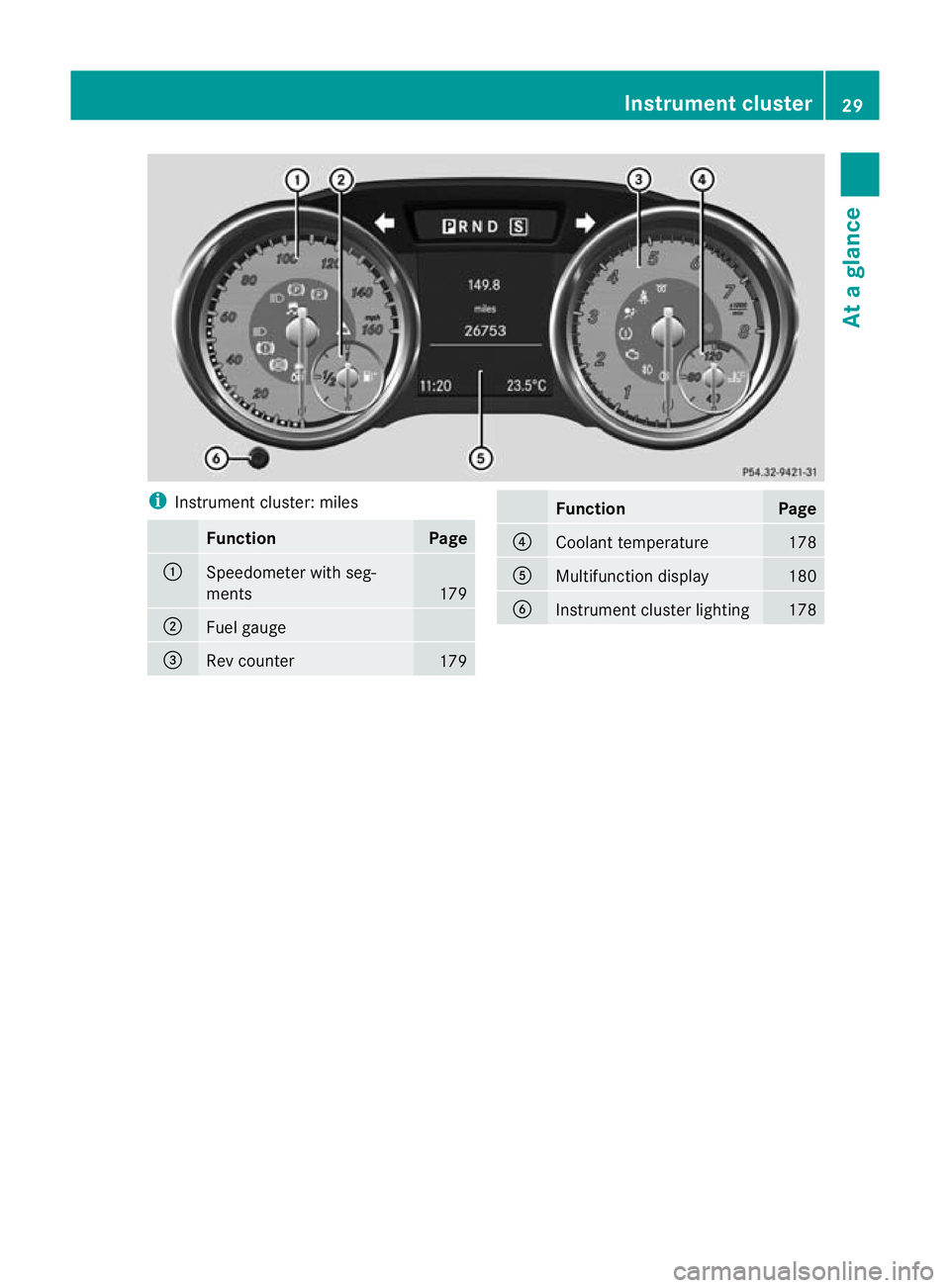
i
Instrument cluster: miles Function Page
:
Speedometer with seg-
ments
179
;
Fuel gauge
=
Rev counter
179 Function Page
?
Coolant temperature 178
A
Multifunction display 180
B
Instrument cluster lighting 178Instrument cluster
29At a glance
Page 33 of 321
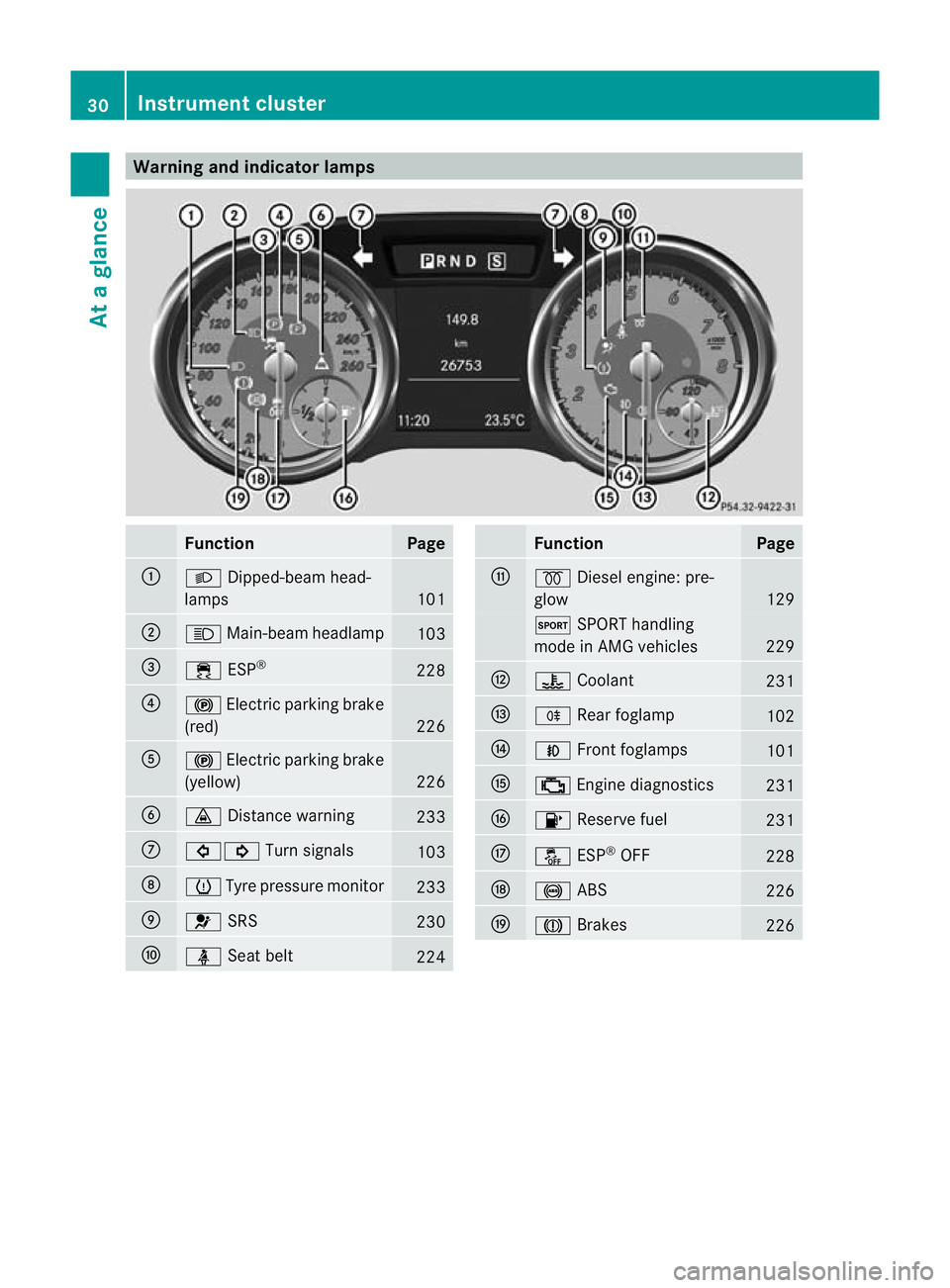
Warning and indicator lamps
Function Page
:
L
Dipped-bea mhead-
lamps 101
;
K
Main-beam headlamp 103
=
÷
ESP® 228
?
!
Electric parkin gbrake
(red) 226
A
!
Electric parking brake
(yellow) 226
B
·
Distance warning 233
C
#!
Turn signals 103
D
h
Tyre pressure monitor 233
E
6
SRS 230
F
ü
Seat belt 224 Function Page
G
%
Diesel engine: pre-
glow 129
M
SPORT handling
mode in AMG vehicles 229
H
?
Coolant 231
I
R
Rearf oglamp 102
J
N
Front foglamps 101
K
;
Engine diagnostics 231
L
8
Reserve fuel 231
M
å
ESP®
OFF 228
N
!
ABS 226
O
J
Brakes 22630
Instrument clusterAt a glance
Page 125 of 321
X
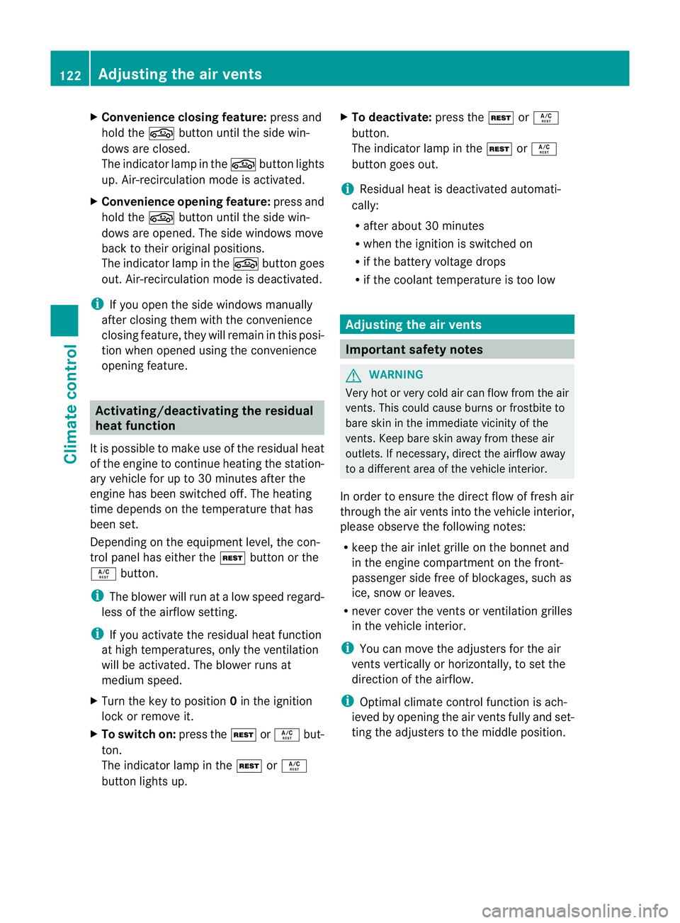
Convenience closing feature: press and
hold the gbutton until the side win-
dows are closed.
The indicator lamp in the gbutton lights
up. Air-recirculation mode is activated.
X Convenience opening feature: press and
hold the gbutton until the side win-
dows are opened. The side windows move
back to their original positions.
The indicator lamp in the gbutton goes
out .Air-recirculation mode is deactivated.
i If you open the side windows manually
after closing them with the convenience
closing feature, they will remain in this posi-
tion when opened using the convenience
opening feature. Activating/deactivating the residual
heat function
It is possible to make use of the residual heat
of the engine to continue heating the station-
ary vehicle for up to 30 minutes after the
engine has been switched off .The heating
time depends on the temperature that has
been set.
Depending on the equipment level, the con-
trol panel has either the Ìbutton or the
Á button.
i The blower will run at a low speed regard-
less of the airflow setting.
i If you activate the residual heat function
at high temperatures, only the ventilation
will be activated. The blower runs at
medium speed.
X Turn the key to position 0in the ignition
lock or remove it.
X To switch on: press theÌorÁ but-
ton.
The indicator lamp in the ÌorÁ
button lights up. X
To deactivate: press theÌorÁ
button.
The indicator lamp in the ÌorÁ
button goes out.
i Residual heat is deactivated automati-
cally:
R after about 30 minutes
R when the ignition is switched on
R if the battery voltage drops
R if the coolant temperature is too low Adjusting the air vents
Important safety notes
G
WARNING
Very hot or very cold air can flow from the air
vents.T his could cause burns or frostbite to
bare skin in the immediate vicinity of the
vents.K eep bare skin away from these air
outlets. If necessary, direct the airflow away
to a different area of the vehicle interior.
In order to ensure the direct flow of fresh air
through the air vents into the vehicle interior,
please observe the following notes:
R keep the air inlet grille on the bonnet and
in the engine compartment on the front-
passenger side free of blockages, such as
ice, snow or leaves.
R never cover the vents or ventilation grilles
in the vehicle interior.
i You can move the adjuster sfor the air
vents vertically or horizontally, to set the
direction of the airflow.
i Optimal climate control function is ach-
ieved by opening the air vents fully and set-
ting the adjusters to the middle position. 122
Adjusting the air ventsClimate control
Page 138 of 321
Problem Possible causes/consequences and
M Solutions
The coolant tempera-
ture display is showing
more than 120 †. The
coolant warning lamp
may also be lit and a
warning tone may
sound. The coolant level is too low. The coolant is too hot and the engine
is no longer being cooled sufficiently.
X Stop as soon as possible and allow the engine and the coolant
to cool down.
X Check the coolant level (Y page 251). Observe the warning
notes as you do so and top up the coolant if necessary. If the coolant level is correct, the engine radiator fan may be faulty.
The coolant is too hot and the engine is no longer being cooled
sufficiently.
X If the coolant temperature is less than 120 †, you can continue
driving to the nearest qualified specialist workshop.
X Avoid heavy loads on the engine as you do so, e.g. driving on
mountain roads and stop-start traffic. Manual transmission
Important safety notes
G
WARNING
The movement of the pedals must not be
impaired in any way. Do not keep any objects
in the driver's footwell. Make sure that floor-
mats or carpets are correctly secured and
that there is sufficient clearance for the ped-
als.
Do not place several floormats on top of one
another. G
WARNING
Do not change down for additional engine
braking on a slippery road surface. This could
cause the drive wheels to lose their grip and
the vehicle could skid. This could cause you
to lose control of your vehicle and cause an
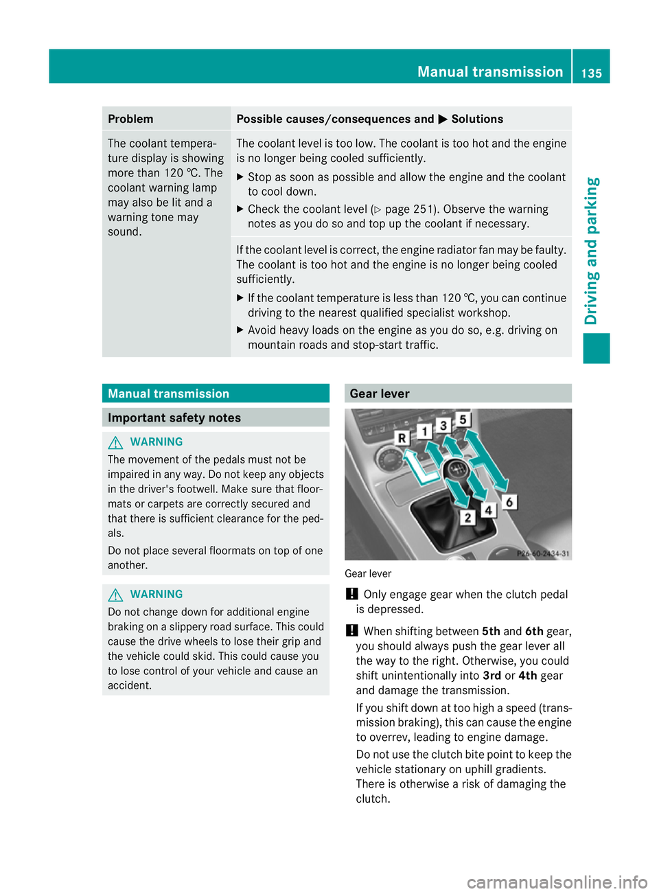
accident. Gear lever
Gear lever
!
Only engage gear when the clutch pedal
is depressed.
! When shifting between 5thand 6thgear,
you should always push the gear lever all
the way to the right. Otherwise, you could
shift unintentionally into 3rdor4th gear
and damage the transmission.
If you shift down at too high a speed (trans-
mission braking), this can cause the engine
to overrev, leading to engine damage.
Do not use the clutch bite point to keep the
vehicle stationary on uphill gradients.
There is otherwise a risk of damaging the
clutch. Manual transmission
135Driving and parking Z
Page 181 of 321
Useful information
i This Owner's Manual describes all models
and all standard and optional equipment
available to your vehicle at the time of pub-
lication of the Owner's Manual. Country-
specific deviations are possible. Please
note that your vehicle may not be equipped
with all features described. This also
applies to safety-relevan tsystems and
functions.
i Please read the information on qualified
specialist workshops (Y page 22).Important safety notes
You will find an illustration of the instrument
cluster in the "At a glance" section
(Y page 28). G
WARNING
Only use the on-board computer when road
and traffic conditions permit .You would oth-
erwise be distracted and unable to concen-
trate properly on driving, and could cause an
accident. G
WARNING
No messages will be displayed if either the
instrument cluster or the multifunction dis-
play is inoperative.
As a result, you will not be able to see infor-
mation about your driving conditions, such as
speed, outside temperature, warning and indi-
cator lamps, display messages or system fail-
ures. Driving characteristics may be impaired.
Adjust your driving style and vehicle speed
accordingly.
Contact a qualified specialist workshop
immediately. G
WARNING
The on-board computer only records and dis-
plays malfunctions and warnings from certain
systems. For this reason, you should always make sure that your vehicle is safe to use. You
could otherwise cause an accident by driving
an unsafe vehicle.
G
WARNING
The operating safety of your vehicle could be
impaired if maintenance work is carried out
incorrectly. This could cause you to lose con-
trol of your vehicle and cause an accident.
Moreover, the safety systems may no longer
be able to protect you or others as they are
designed to do.
Always have service work carried out at a
qualified specialist workshop. Displays and operation
Instrument cluster lighting
The brightness control knob is located on the
bottom left of the instrument cluster
(Y page 28).
X Turn the brightness control knob clockwise
or anti-clockwise.
Instrument cluster: if the light switch is set
to Ã, TorL, brightness control
takes ambient light conditions into account.
i The light sensor in the instrument cluster
automatically controls the brightness of
the multifunction display.
In daylight, the displays in the instrument
cluster are not illuminated.
Displays and switches in the vehicle
interior: if the light switch is set to Ã,
brightness control takes ambient light condi-
tions into account .Ifthe light switch is set to
T orL, brightness control does not
take ambient light conditions into account. Coolant temperature gauge
The coolant temperature gauge is in the
instrumentc lusteront he right-hand side. 178
Displays and operationOn-board computer and displays
Page 182 of 321
The reading may rise up to 120
†undernor-
mal driving conditions if the coolant has been
filled correctly.
At high outside temperatures and when driv-
ing uphill, the coolant temperature may rise
to the end of the scale. Rev counter
The red band in the rev counter indicates the
engine's overrevving range.
! Do not drive in the overrevving range.
Doing so will damage the engine.
The fuel supply is interrupted to protec tthe
engine when the red band is reached. Outside temperature display
The outside temperature displayi s in the mul-
tifunction display (Y page 180). G
WARNING
At temperatures just above freezing point, the
street may be icy, especially in wooded areas
or on bridges. If you do not adapty our driving
style to the conditions, the vehicle could skid.
For this reason, adapt your driving style and
speed to the weather conditions.
Changes in the outside temperature are dis-
played after a short delay. Speedometer with segments
The segments in the speedometer indicate
which speed range is available.
Cruise control (Y page 151) activated:
The segments light up from the stored speed
to the maximum speed.
Variable SPEEDTRONIC (Y page 153) activa-
ted:
The segments light up from the start of the
scale to the selected limit speed.
DISTRONIC PLUS (Y page 156) activated: One or two segments in the set speed range
light up.
DISTRONIC PLUS detects a vehicle in front:
The segments between the speed of the vehi-
cle in front and the stored speed light up.
Operating the on-board computer
Overview The on-board computer is activated as soon
as you turn the key to position
1in the ignition
lock.
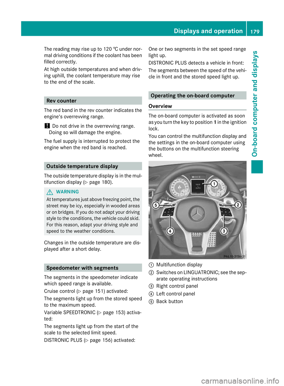
You can control the multifunction display and
the settings in the on-board computer using
the buttons on the multifunction steering
wheel. :
Multifunction display
; Switches on LINGUATRONIC; see the sep-
arate operating instructions
= Right control panel
? Left control panel
A Back button Displays and operation
179On-board computer and displays Z