ECO mode MERCEDES-BENZ SLK ROADSTER 2014 Owners Manual
[x] Cancel search | Manufacturer: MERCEDES-BENZ, Model Year: 2014, Model line: SLK ROADSTER, Model: MERCEDES-BENZ SLK ROADSTER 2014Pages: 357, PDF Size: 10.22 MB
Page 8 of 357
ATTENTION ASSIST
Activating/deactivating ................ .212
Display message ............................ 237
Function/notes ............................ .191
ATTENTION ASSIST
see ATTENTION ASSIST
Audio menu (on-board computer) .... 207
Authorised workshop
see Qualified specialist workshop
AUTO lights
Display message ............................ 233
see Lights
Automatic engine start (ECO start/
stop function) ................................... .147
Automatic engine switch-off (ECO
start/stop function) .......................... 146
Automatic headlamp mode .............. 111
Automatic transmission
Accelerator pedal position ............. 153
Automatic drive program .............. .155
Changing gear ............................... 153
Display message ............................ 245
Driving tips ................................... .153
Emergency running mode .............. 158
Kickdown ....................................... 153
Manual drive program .................... 155
Manual drive program (vehicles
with Sports package AMG) ............ 156
Overview ........................................ 152
Problem (fault) ............................... 158
Program selector button ................ 154
Pulling away ................................... 144
Releasing the parking lock man-
ually ............................................... 158
Selector lever ................................ 152
Starting the engine ........................ 144
Steering wheel gearshift paddle s... 154
Transmission position display ........ 152
Transmission positions .................. 153
Automatic transmission emer-
gency running mode ......................... 158B
BAS (Brake Assist System) ................. 61
BAS PLUS (Brake Assist System
PLUS) .................................................... 61 Battery (key)
Checking .......................................... 75
Important safety notes .................... 75
Replacing ......................................... 75
Battery (vehicle)
Charging ........................................ 303
Display message ............................ 235
Important safety notes .................. 300
Jump starting ................................. 304
Overview ........................................ 300
Belt
see Seat belts
Belt tensioner
Activation ......................................... 47
Blind Spot Assist
Activating/deactivating ................. 212
Display message ............................ 239
Notes/function .............................. 194
Bonnet
Active bonnet (pedestrian protec-tion) ............................................... 280
Closing ........................................... 281
Display message ............................ 247
Important safety notes .................. 280
Opening ......................................... 281
Boot
Emergency release .......................... 83
Important safety notes .................... 81
Opening (automatically from out-
side) ................................................. 82
Opening/closing (manually from
outside) ............................................ 82
Overview .......................................... 81
Boot lid
Display message ............................ 247
Opening dimensions ...................... 349
Opening/closing .............................. 81
Boot load (maximum) ........................ 349
Boot separator
Display message ............................ 248
General notes .................................. 89
Opening/closing .............................. 90
Bottle holders .................................... 267
Brake
EBD .................................................. 66
Brake Assist
see BAS (Brake Assist System) Index
5
Page 16 of 357
Switching the daytime driving
lights on/off (on-board com-
puter) ............................................. 214
Switching the exterior lighting
delayed switch-off on/off (on-
board computer) ............................ 215
Switching the surround lighting
on/off (on-board computer) .......... 215
Turn signals ................................... 113
see Interior lighting
see Replacing bulbs
LIM indicator lamp
Cruise control ................................ 169
DISTRONIC PLUS ........................... 173
Variable SPEEDTRONIC ................. 181
Limiting the speed
see SPEEDTRONIC
Locking
see Central locking
Locking (doors)
Automatic ........................................ 80
Emergency locking ........................... 80
From inside (central locking but-
ton) .................................................. 79
Locking centrally
see Central locking
Locking verification signal (on-
board computer) ............................... 217
Luggage cover
see Boot separator
Lumbar support ................................... 99 M
M+S tyres ........................................... 316
MAGIC SKY CONTROL ......................... 92
Main-beam headlamps
Changing bulb s.............................. 119
Display message ............................ 232
Switching on/of f........................... 113
Manual transmission
Engaging reverse gear ................... 151
Gear lever ...................................... 151
Pulling away ................................... 144
Shift recommendation ................... 152
Starting the engine ........................ 144
Matt finish (cleaning instructions) .. 288Media Interface
see Separate operating instructions
Memory card (audio) ......................... 207
Memory function ............................... 106
Mercedes-Benz Service Centre
see Qualified specialist workshop
Message memory (on-board com-
puter) .................................................. 222
Messages
see Display messages
Mirrors
see Exterior mirrors
see Rear-view mirror
see Vanity mirror (in sun visor)
Mobile phone
Frequencies ................................... 340
Installation ..................................... 340
Menu (on-board computer) ............ 208
Notes/placing in the bracket ......... 270
Transmission output (maximum) .... 340
Modifying the programming (key) ..... 74
MOExtended tyres ............................. 296
Motorway mode ................................ 114
MP3
see Separate operating instructions
Multifunction display
Function/note s............................. 202
Permanent display ......................... 213
Multifunction steering wheel
Operating the on-board compute r..2 01
Overview .......................................... 33 N
Navigation Menu (on-board computer) ............ 205
NECK-PRO head restraints
Important safety notes .................... 49
Operation ......................................... 49
Resetting after being triggered ....... .50
Notes on running in a new vehicle .. 140 O
Occupant safety Automatic measures after an acci-
dent ................................................. 51
Children in the vehicle ..................... 51 Index
13
Page 20 of 357
Speedometer
Activating/deactivating the addi-
tional speedometer ........................ 213
Digital ............................................ 205
In the Instrument cluster ................. 30
Segments ...................................... 201
Selecting the unit of measure-
ment ..............................................2 13
SPEEDTRONIC
Deactivating variable ..................... 182
Display message ............................ 241
Function/notes ............................ .180
Important safety notes .................. 180
LIM indicator lamp ......................... 181
Permanent ..................................... 182
Selecting ........................................ 181
Storing the current spee d.............. 181
Variabl e......................................... 181
SPORT handling mode
Activating/deactivating (AMG
vehicles) .......................................... 64
Warning lamp ................................. 255
Start/stop function
see ECO start/stop function
Starting (engine) ................................ 143
Status overview (on-board com-
puter) .................................................. 210
Steering (display message) .............. 248
Steering wheel
Adjusting (electrically) ................... 101
Adjusting (manually) ...................... 101
Button overview ............................... 33
Buttons (on-board computer) ......... 201
Cleaning ......................................... 291
Gearshift paddle s........................... 154
Important safety notes .................. 100
Storing settings (memory func-
tion) ............................................... 106
Steering wheel gearshift paddles .... 154
Stopwatch (RACETIMER) ................... 219
Stowage areas ................................... 264
Stowage compartments
Armrest (front) ............................... 265
Armrest (under) ............................. 265
Centre console .............................. 265
Cup holde r..................................... 267
Door ............................................... 266 Glove compartment ....................... 264
Important safety information ......... 264
Rear wall ........................................ 266
Spectacles compartment ............... 265
Stowage net ....................................... 266
Stowage space
Display message ............................ 248
Stowage net ................................... 266
Summer tyres .................................... 316
Sun visor ............................................ 268
Surround lighting (on-board com-
puter) .................................................. 215 T
Tail lamps Display message ............................ 232
see Lights
Technical data
Capacities ...................................... 342
Emergency spare wheel ................. 337
Information .................................... 340
Tyres/wheels ................................. 328
Vehicle data ................................... 349
Telephone
Accepting a cal l............................. 209
Display message ............................ 248
Menu (on-board computer) ............ 208
Number from the phone book ........ 209
Redialling ....................................... 209
Rejecting/ending a call ................. 209
Telephone compartment ................ 265
Temperature
Coolant .......................................... 200
Coolant (on-board computer) ......... 219
Engine oil (on-board computer) ...... 219
Outside temperature ...................... 201
Setting (climate control )................ 131
TEMPOMAT
Function/note s............................. 168
Time
see Separate Owner's manual
Timing (RACETIMER) ......................... 219
TIREFIT kit .......................................... 297
Total distance recorder .................... 204
Tow-away protection
Activating ......................................... 69
Deactivating ..................................... 69 Index
17
Page 37 of 357
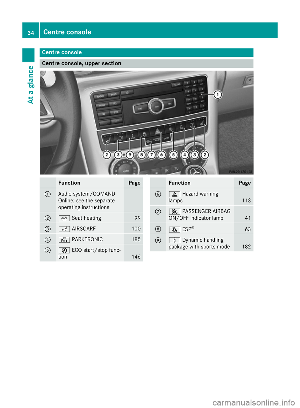
Centre console
Centre console, upper section
Function Page
:
Audio system/COMAND
Online; see the separate
operating instructions
;
c
Seat heating 99
=
Ò
AIRSCARF 100
?
c
PARKTRONIC 185
A
è
ECO start/stop func-
tion 146 Function Page
B
£
Hazard warning
lamps 113
C
4
PASSENGER AIRBAG
ON/OFF indicator lamp 41
D
å
ESP® 63
E
à
Dynamic handling
package with sports mode 18234
Centre consoleAt a glance
Page 51 of 357
Therefore, have pyrotechnic belt tensioners
which have been triggered immediately
replaced at a qualified specialist workshop.
Mercedes-Benz recommends that you have
the vehicle towed to a qualified specialist
workshop after an accident. This is particu-
larly important if a belt tensioner or an airbag
have been triggered.
An electric motor is used by PRE-SAFE ®
to
trigger the tightening of the seat belt in haz-
ardous situations. This procedure is reversi-
ble.
If the belt tensioners or airbags are deployed, you will hear a bang, and a small amount of
powder may also be released. The 6
restraint system warning lamp lights up.
Only in rare cases will the bang affect your
hearing. The powder that is released gener-
ally does not constitute a health hazard, how-
ever it may cause short-term breathing diffi-
culties to persons suffering from asthma or
other pulmonary conditions. If it is safe to do so, you should leave the vehicle immediately
or open a window in order to prevent breath-
ing difficulties.
Mode of operation During the first stage of a collision, the
restraint system control unit evaluates impor-
tant physical data relating to vehicle deceler- ation or acceleration, such as:
R duration
R direction
R intensity
Based on the evaluation of this data, the
restraint system control unit triggers the belt
tensioners in the event of a frontal or rear
collision.
If the restraint system control unit detects a
high accident severity, additional compo-
nents of the restraint system are activated
independently of one another in certain fron- tal collision situations:
R Front airbags Depending on the person in the front-
passenger seat, the front-passenger front air-
bag is either enabled or disabled. The front-
passenger front airbag can only be deployed
in an accident if the PASSENGER AIR BAG OFFindicator lamp is off. Observe the information
on the PASSENGER AIR BAG OFF indicator
lamp (Y page 41).
Your vehicle has dual-stage front airbags. In
the first deployment threshold, the front air-
bag is filled with propellant gas to reduce the risk of injuries. The front airbag is filled with
the maximum amount of propellant gas if the
second deployment threshold is then reached within a few milliseconds.
The activation thresholds for the belt ten-
sioner and airbag are determined by evaluat-
ing the vehicle deceleration or vehicle accel-
eration that occurs at different points in the
vehicle. This process is pre-emptive in nature. The triggering process must take place in
good time at the start of the collision.
The rate of vehicle deceleration or accelera-
tion and the direction of the force are essen- tially determined by:
R the distribution of the force during the
impact
R the collision angle
R the deformation characteristics of the vehi-
cle
R the characteristics of the object with which
the vehicle has collided
Factors which can only be seen and measured
after a collision has occurred do not play a
decisive role in the deployment of an airbag,
nor do they provide an indication of airbag
deployment.
The vehicle may be deformed significantly
without an airbag being deployed. This is the
case if only parts which are relatively easily
deformed are affected and the rate of decel-
eration is not high. Conversely, an airbag may be deployed even though the vehicle suffers
only minor deformation. This is the case if, for
example, very rigid vehicle parts such as lon- 48
Occupant safetySafety
Page 60 of 357
Suitable positioning of the child
restraint system
Introduction Only child restraint systems which are
approved in accordance with the ECE stand-
ard ECE R44 are permitted for use in the vehi-
cle.
Rearward-facing child restraint systems with-
out a transponder for automatic child seat
recognition may not be installed on the front- passenger seat.
Child restraint system on the front-
passenger seat – if you secure a child in a
child restraint system on the front-passenger seat:
X Always pay attention to the instructions
under "Child restraint system on the front-
passenger seat" (Y page 54).
There you will find instructions on how to
correctly route the shoulder belt strap from the front-passenger seat belt loop to the
shoulder belt guide on the child restraint
system (Y page 55).
X Move the front-passenger seat as far back
as possible and into the highest position.
X Move the backrest to an almost vertical
position.
The entire base of the child restraint sys-
tem must always rest on the seat cushion of
the front-passenger seat. The backrest of
the forwards-facing child restraint system
must, as far as possible, be resting on the
backrest of the front-passenger seat. The
child restraint system must not touch the
roof. Adjust the backrest angle accord-
ingly. Also observe the child restraint sys-
tem manufacturer's installation instruc-
tions.
X Move the seat cushion angle to the highest,
most vertical position.
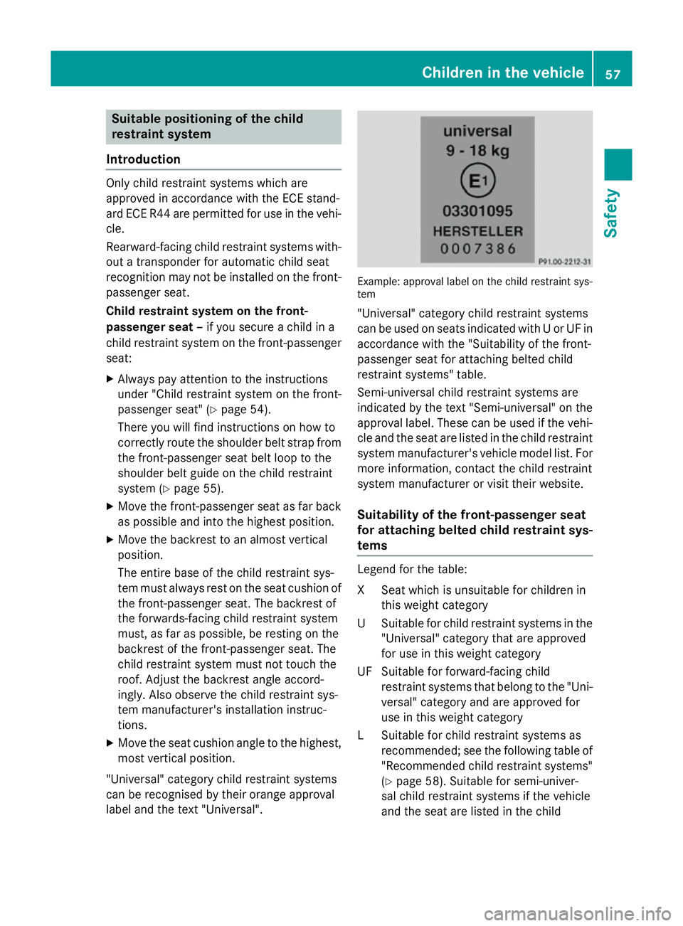
"Universal" category child restraint systems
can be recognised by their orange approval
label and the text "Universal". Example: approval label on the child restraint sys-
tem
"Universal" category child restraint systems
can be used on seats indicated with U or UF in
accordance with the "Suitability of the front-
passenger seat for attaching belted child
restraint systems" table.
Semi-universal child restraint systems are
indicated by the text "Semi-universal" on the
approval label. These can be used if the vehi- cle and the seat are listed in the child restraint
system manufacturer's vehicle model list. For more information, contact the child restraint
system manufacturer or visit their website.
Suitability of the front-passenger seat
for attaching belted child restraint sys-
tems Legend for the table:
XS
eat which is unsuitable for children in
this weight category
US uitable for child restraint systems in the
"Universal" category that are approved
for use in this weight category
UF Suitable for forward-facing child restraint systems that belong to the "Uni-
versal" category and are approved for
use in this weight category
LS uitable for child restraint systems as
recommended; see the following table of
"Recommended child restraint systems" (Y page 58). Suitable for semi-univer-
sal child restraint systems if the vehicle
and the seat are listed in the child Children in the vehicle
57Safety Z
Page 61 of 357
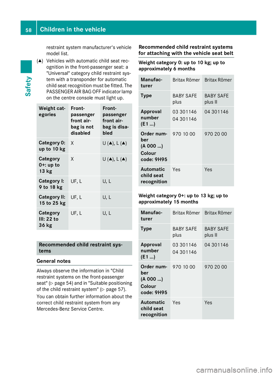
restraint system manufacturer's vehicle
model list.
(▲) Vehicles with automatic child seat rec- ognition in the front-passenger seat: a
"Universal" category child restraint sys-
tem with a transponder for automatic
child seat recognition must be fitted. The
PASSENGER AIR BAG OFF indicator lamp
on the centre console must light up. Weight cat-
egories Front-
passenger
front air-
bag is not
disabled Front-
passenger
front air-
bag is disa-
bled
Category 0:
up to 10 kg X U (▲), L (▲)
Category
0+: up to
13 kg
X U (▲), L (▲)
Category I:
9 to 18 kg
UF, L U, L
Category II:
15 to 25 kg UF, L U, L
Category
III: 22 to
36 kg
UF, L U, L
Recommended child restraint sys-
tems
General notes Always observe the information in "Child
restraint systems on the front-passenger
seat" (Y page 54) and in "Suitable positioning
of the child restraint system" (Y page 57).
You can obtain further information about the correct child restraint system from any
Mercedes-Benz Service Centre. Recommended child restraint systems
for attaching with the vehicle seat belt Weight category 0: up to 10 kg; up to
approximately 6 months
Manufac-
turer
Britax Römer Britax Römer
Type
BABY SAFE
plus BABY SAFE
plus II
Approval
number
(E1 ...)
03 301146
04 301146 04 301146
Order num-
ber
(A 000 ...)
Colour
code: 9H95
970 10 00 970 20 00
Automatic
child seat
recognition
Yes Yes
Weight category 0+: up to 13 kg; up to
approximately 15 months
Manufac-
turer
Britax Römer Britax Römer
Type
BABY SAFE
plus BABY SAFE
plus II
Approval
number
(E1 ...)
03 301146
04 301146 04 301146
Order num-
ber
(A 000 ...)
Colour
code: 9H95
970 10 00 970 20 00
Automatic
child seat
recognition
Yes Yes58
Children in the vehicleSafety
Page 108 of 357
The rear-view mirror and the exterior mirror
on the driver's side automatically go into anti- dazzle mode if the following conditions are
met simultaneously:
R the ignition is switched on and
R incident light from headlamps strikes the
sensor in the rear-view mirror
The mirrors do not dip if reverse gear is
engaged or if the interior lighting is switched
on. Parking position of the exterior mirror
on the front-passenger side
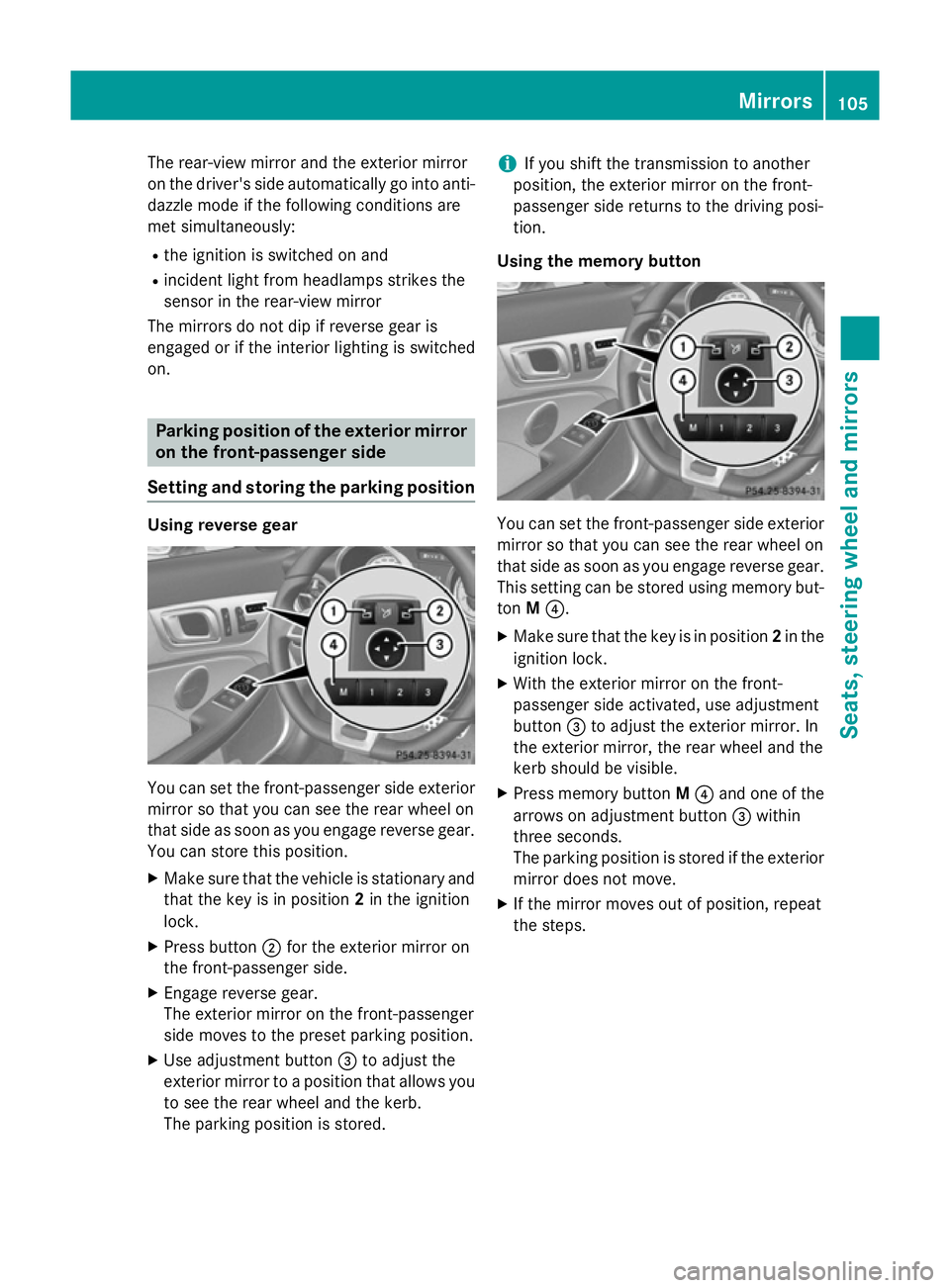
Setting and storing the parking position Using reverse gear
You can set the front-passenger side exterior
mirror so that you can see the rear wheel on
that side as soon as you engage reverse gear.
You can store this position.
X Make sure that the vehicle is stationary and
that the key is in position 2in the ignition
lock.
X Press button ;for the exterior mirror on
the front-passenger side.
X Engage reverse gear.
The exterior mirror on the front-passenger
side moves to the preset parking position.
X Use adjustment button =to adjust the
exterior mirror to a position that allows you to see the rear wheel and the kerb.
The parking position is stored. i
If you shift the transmission to another
position, the exterior mirror on the front-
passenger side returns to the driving posi-
tion.
Using the memory button You can set the front-passenger side exterior
mirror so that you can see the rear wheel on
that side as soon as you engage reverse gear.
This setting can be stored using memory but-
ton M?.
X Make sure that the key is in position 2in the
ignition lock.
X With the exterior mirror on the front-
passenger side activated, use adjustment
button =to adjust the exterior mirror. In
the exterior mirror, the rear wheel and the
kerb should be visible.
X Press memory button M? and one of the
arrows on adjustment button =within
three seconds.
The parking position is stored if the exterior mirror does not move.
X If the mirror moves out of position, repeat
the steps. Mirrors
105Seats, steering wheel and mirrors Z
Page 113 of 357
Useful information
i This Owner's Manual describes all mod-
els, series and optional equipment for your
vehicle that were available at the time of
going to press. National variations are pos- sible. Note that your vehicle may not be
equipped with all of the functions descri-
bed. This is also the case for systems and
functions relevant to safety.
i Read the information on qualified special-
ist workshops: (Y page 24). Exterior lighting
General notes
For reasons of safety, Mercedes-Benz recom- mends that you drive with the lights switched
on even during the daytime. In some coun-
tries, operation of the headlamps varies due
to legal requirements and self-imposed obli-
gations. Driving abroad
General notes If your journey takes you to countries where
vehicles are driven on the opposite side of the
road to the country in which the vehicle is
registered, your headlamps must be switched to symmetrical dipped beam as soon as pos-
sible after crossing the border (exception:
vehicles with halogen headlamps). This pre-
vents oncoming traffic from being dazzled.
Symmetrical lights do not illuminate as large
an area of the edge of the carriageway.
Vehicles with halogen headlamps It is not necessary to switch your headlamps
to symmetrical dipped beam when driving in
countries where vehicles are driven on the
opposite side of the road to the country in
which the vehicle is registered. Legal require- ments are fulfilled without switching the
headlamps to symmetrical dipped beam.
Vehicles with Intelligent Light System X
Before crossing the border, set the head-
lamps to symmetrical dipped beam; after
returning, reset them to asymmetrical
dipped beam via the "Dipped-beam head-
lamps for driving on the right/left" function
in the on-board computer (Y page 214).
If the headlamps are converted to symmetri-
cal dipped beam, the "motorway mode" and
"extended range foglamps" functions are not
available. Setting the exterior lighting
Setting options Exterior lighting can be set by:
R using the light switch
R headlamp range control (vehicles with hal-
ogen headlamps only) (Y page 112)
R using the combination switch
(Y page 113)
R using the on-board computer
(Y page 214)
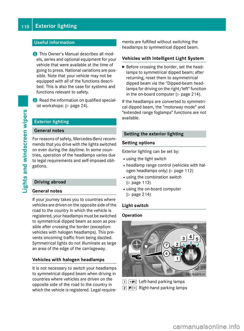
Light switch Operation
1
W
Left-hand parking lamps
2 X
Right-hand parking lamps 110
Exterior lightingLights and windscreen wipers
Page 117 of 357
ated five times (Y
page 120) while the lights
are on and the engine is running. When you
switch off the ignition, the automatic head-
lamp cleaning system is reset and counting is
resumed from 0. Intelligent Light System
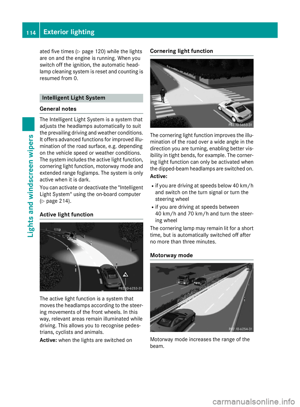
General notes The Intelligent Light System is a system that
adjusts the headlamps automatically to suit
the prevailing driving and weather conditions. It offers advanced functions for improved illu-
mination of the road surface, e.g. depending
on the vehicle speed or weather conditions.
The system includes the active light function, cornering light function, motorway mode and
extended range foglamps. The system is only active when it is dark.
You can activate or deactivate the "IntelligentLight System" using the on-board computer
(Y page 214).
Active light function The active light function is a system that
moves the headlamps according to the steer-
ing movements of the front wheels. In this
way, relevant areas remain illuminated while
driving. This allows you to recognise pedes-
trians, cyclists and animals.
Active: when the lights are switched on Cornering light function
The cornering light function improves the illu-
mination of the road over a wide angle in the direction you are turning, enabling better vis-
ibility in tight bends, for example. The corner- ing light function can only be activated when
the dipped-beam headlamps are switched on.
Active:
R if you are driving at speeds below 40 km/h
and switch on the turn signal or turn the
steering wheel
R if you are driving at speeds between
40 km/h and 70 km/h and turn the steer-
ing wheel
The cornering lamp may remain lit for a short
time, but is automatically switched off after
no more than three minutes.
Motorway mode Motorway mode increases the range of the
beam.114
Exterior lightingLights and windscreen wipers