check engine light MERCEDES-BENZ SLS COUPE 2010 Owners Manual
[x] Cancel search | Manufacturer: MERCEDES-BENZ, Model Year: 2010, Model line: SLS COUPE, Model: MERCEDES-BENZ SLS COUPE 2010Pages: 361, PDF Size: 6.32 MB
Page 11 of 361
DVD
Copy protection ............................. 167
Disc ............................................... 167
Selecting atrack ............................ 176
DVD audio
Operation (on-board computer) .....235
DVD playbac kconditions ................. 191
DVD video Operating (on-board computer) .....236
Dynamic route guidance ................... 119
Switching on/off ........................... 119
TMC/TMCPro ................................ 119E
EASY-ENTRY feature .........................207
Activating/deactivating (on-
board computer) ............................ 240
EASY-EXIT feature ............................. 207
Crash-responsive ........................... 207
EBD
Display message ............................ 299
EBV (electronic brake force distri-
bution) .................................................. 49
Electronic brake force distribution See EBV ........................................... 49
Electronic Stability Program
see ESP ®
Electronic Traction Support see ETS
Emergency call 999 or 112 ..............129
Emergency key element ...................321
Lost ............................................... 320
Emergency spare wheel
Inflating ......................................... 333
Stowing .......................................... 334
Technical data ............................... 355
Emergency unlocking
Boot ............................................... 322
Vehicle .......................................... .322
Engine
Running irregularl y......................... 315
Starting .................................. 202, 220
Starting problems ..........................315
Starting the engine with the key ....220
Starting with KEYLESS GO .............220
Starting with the key ..................... .220
Stopping ........................................ 222Engine diagnostics warning lamp
....310
Engine electronics .............................346
Malfunction ................................... .315
Engine number .................................. 349
Engine oil ........................................... 350
Capacities ...................................... 269
Checking the oil level (dipstick) .....269
Consumption ................................. 269
Display mes-
sag e....................................... 302, 303
Filler neck ...................................... 269
Temperature display (on-board
computer) ...................................... 241
Temperature gauge ........................ 229
Topping up ..................................... 269
Ensemble ........................................... 161
ESP ®
(Electronic Stability Pro-
gram) .................................................... 47
Activating/deactivating .............47, 48
AMG menu (on-board computer) ...241
Warning lamp ..................47, 308, 309
ETS (Electronic Traction Support) ...... 48
Example of operation ..........................66
Exterior lighting Delayed switch-off (on-board
computer) ...................................... 239
Exterior mirrors
Adjusting ....................................... 208
Anti-dazzle mode (automatic) ........209
Folding in/ou t(automatically) .......209
Folding in/ou t(electrically) ...........208
Folding in whe nlocking (on-board
computer) ...................................... 240
Malfunction ................................... .318
Parking position ............................. 209
Resetting ....................................... 209
Storing settings ............................. 210
Exterior view
Overview .......................................... 22
External authorisation ........................77
External data Deleting (convenience telephone) .137
Importing (convenience tele-
phone )................................... 136, 155
External devices (Media Interface)
Connecting .................................... 1848
Index BA 197 ECE RE 2010/6a; 1; 2, en-GB
sabbae uV ersion: 3.0.3.6
2010-05-07T14:19:43+02:00 - Seite 8
Page 13 of 361
PASSENGER AIRBAG OFF
........42, 307
Reserve fuel ................................... 312
Seat bel t........................................ 311
SRS .......................................... 35, 309
THERMOTRONIC (malfunction) ......307
Indicator lamps
see Warning and indicator lamps ...308
Input restriction
Navigation ........................................ 80
Instrument cluster ............................229
On-board computer .......................238
Overview .......................................... 25
Instrument lighting ...........................239
Interior lighting Automatic control system ..............217
Delayed switch-off (on-board
computer) ...................................... 239
Emergency lighting ........................217
Manual control ............................... 217
Reading lamp ................................. 217
Interior motion sensor ........................50
Intermediate stop Deleting ......................................... 105
Entering ......................................... 104
iPod ®
Alphabetic track selection .............188
Connecting to Media Interface ......185
Device variants .............................. 184
Selecting a category/playlis t......... 187 J
Jack .................................................... .288
Operation ....................................... 329
Jump-starting ..................................... 338
Jump leads ..................................... 338
Junction
Entering ......................................... 100K
Key ...................................................... 200
Changing the battery .....................323
Checking the battery .....................323
Convenience closing feature .......... 219
Convenience opening feature ........219
Display message ............................ 303
Emergency key element ................. 321 Loss
............................................... 320
Malfunction ................................... .319
Modifying the programming ...........200
Unlocking/locking vehicle .............200
KEYLESS-GO
Changing the battery .....................323
Display message ............................ 303
Malfunction ................................... .319
Starting the engine ........................220
Keyp ositions
Key ................................................ 203
KEYLESS GO .................................. 202
Kickdown ........................................... 224 L
Lamps see Warning and indicator lamps ...308
Lane recommendations ....................113
Explanation .................................... 114
Licence plate lighting
Display message ............................ 301
Lighting
see Lights
Lights
Automatic headlamp mode ............215
Combination switch .......................214
Daytime driving lights ....................215
Dipped-bea mheadlamps ............... 215
Hazard warning lamps ...................216
Headlamp flasher ........................... 215
Ligh tswitc h................................... 214
Main-beam headlamps ................... 216
Parking lamps ................................ 215
Rea rfoglamp ................................. 216
Side lamps ..................................... 215
Switching surround lighting on/
off (on-board computer) ................. 239
Switching the daytime driving
lights on/off (on-board computer) .238
Switching the exterio rlighting
delayed switch-off on/off (on-
board computer )............................ 239
Turn signals ................................... 216
LIM indicator lamp
Cruise control ................................ 244
Variabl eSPEEDTRONIC .................24610
Index BA 197 ECE RE 2010/6a; 1; 2, en-GB
sabbae uV ersion: 3.0.3.6
2010-05-07T14:19:43+02:00 - Seite 10
Page 38 of 361
SRS (Supplemental Restraint System)
SRS reduces the risk of occupants coming
into contact with the vehicle's interior in the
event of an accident. It can also reduce the
effect of the forces to which occupants are
subjected during an accident.
SRS consists of:
R the 0018 SRS warning lamp
R airbags
R airbag control unit (with crash sensors)
R belt tensioners
R belt force limiters
The 0018 SRS warning lamp
SRS functions are checked regularly when
you switch on the ignition and when the
engine is running. Therefore, malfunctions
can be detected in good time.
The 0018 SRS warning lamp in the instrument
cluster lights up when the ignition is switched
on. It goes out no later than a few seconds
after the engine is started. G
Risk of injury
If SRS is malfunctioning, individual systems
may be activated unintentionally or may not
be triggered in the event of an accident with
a high rate of vehicle deceleration.
A malfunction has occurred if:
R the 0018 SRS warning lamp does not light
up when the ignition is switched on.
R the engine is running and the 0018SRS
warning lamp does not go out after a few
seconds.
R the engine is running and the 0018SRS
warning lamp lights up again.
In this case, have SRS checked immediately
at a qualified specialist workshop. Mercedes-
Benz recommends that you use a Mercedes-
Benz Service Centre for this purpose.
In particular, work relevant to safety or on
safety-related systems must be carried out at
a qualified specialist workshop. Triggering of belt tensioners, belt force
limiters and airbags In the event of a collision, the airbag control
unit evaluates important physical data rela-
ted to the vehicle deceleration or accelera-
tion during the first stage of the collision, such
as:
R
duration
R direction
R magnitude
Based on the evaluation of this data, the air-
bag control unit pre-emptively triggers the
belt tensioners in the first stage.
i The belt tensioners can only be triggered
if the seat belt tongues are correctly
engaged in the seat belt buckles.
If there is an even higher rate of vehicle decel-
eration or acceleration in a longitudinal direc-
tion, the front airbags are also deployed.
Your vehicle has adaptive, two-stage front air-
bags. The airbag control unit evaluates vehi-
cle deceleration or acceleration in the event
of a collision. When the first deployment
threshold is reached, the front airbag is filled
with enough propellant gas to reduce the risk
of injuries. The front airbag is fully deployed
if a second deployment threshold is exceeded
within a few milliseconds.
The belt tensioner and airbag triggering
thresholds are variable and are adapted to the
rate of deceleration or acceleration of the
vehicle. This process is pre-emptive in nature.
The triggering process must take place in
good time at the start of the collision.
i Not all airbags are deployed in an acci-
dent. The different airbag systems work
independently of each other.
How the airbag system works is deter-
mined by the severity of the accident detec-
ted, especially the vehicle deceleration or
acceleration, and the apparent type of acci-
dent:
R head-on collision
R side impact Occupant safety
35Safety
BA 197 ECE RE 2010/6a; 1; 2, en-GB
sabbaeu Version: 3.0.3.6 2010-05-07T14:19:43+02:00 - Seite 35 Z
Page 205 of 361
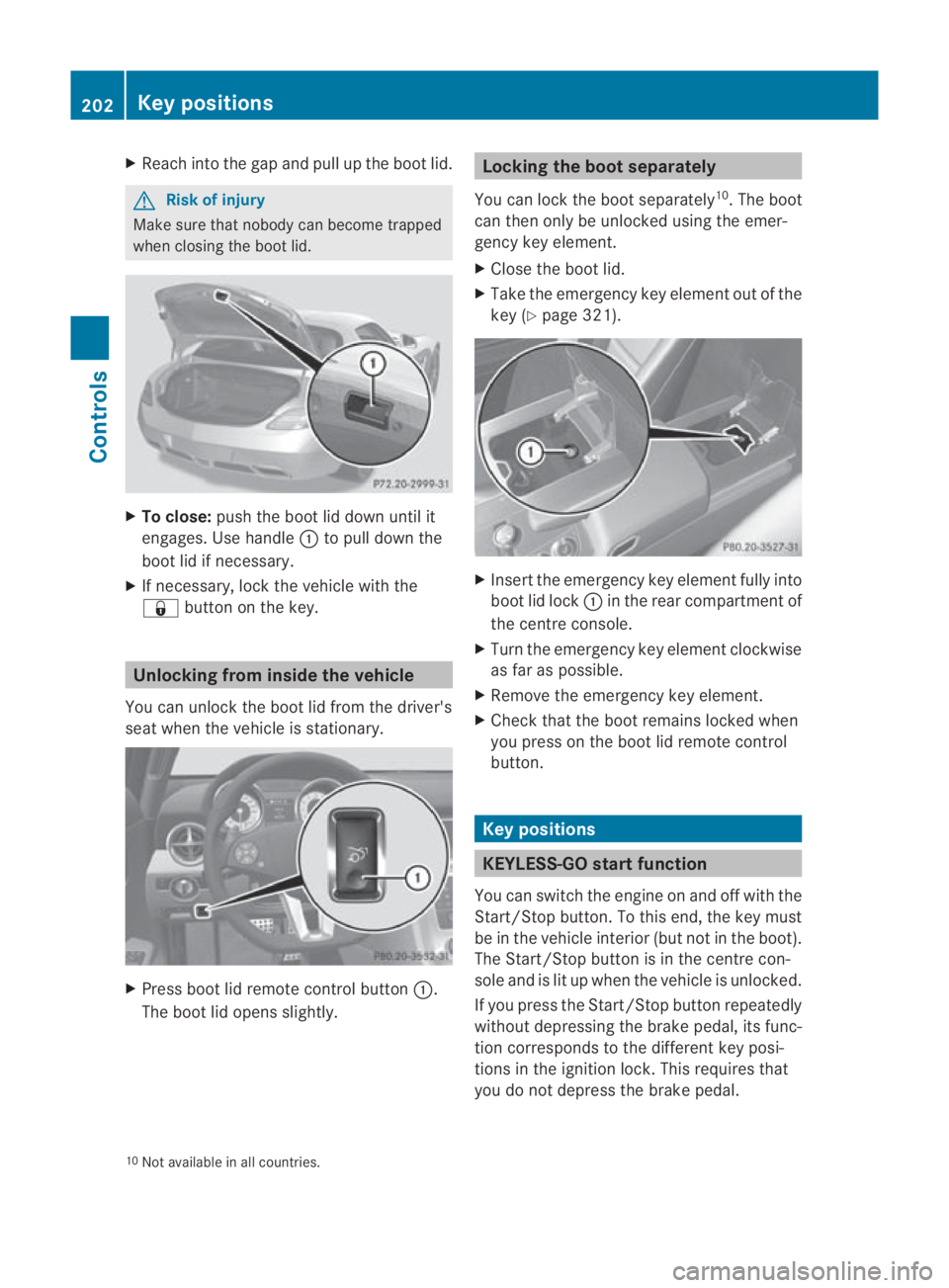
X
Reach into the gap and pull up the boo tlid. G
Risk of injury
Make sure that nobody can become trapped
when closing the boot lid. X
To close: push the boot lid down until it
engages. Use handle 0001to pull down the
boot lid if necessary.
X If necessary, lock the vehicle with the
0009 button on the key. Unlocking from inside the vehicle
You can unlock the boot lid from the driver's
seat when the vehicle is stationary. X
Press boot lid remote control button 0001.
The boot lid opens slightly. Locking the boot separately
You can lock the boot separately 10
.T he boot
can then only be unlocked using the emer-
gency key element.
X Close the boot lid.
X Take the emergency key element out of the
key (Y page 321). X
Insert the emergency key element fully into
boot lid lock 0001in the rear compartment of
the centre console.
X Turn the emergency key element clockwise
as far as possible.
X Remove the emergency key element.
X Check that the boot remains locked when
you press on the boot lid remote control
button. Key positions
KEYLESS-GO startf
unction
You can switch the engine on and off with the
Start/Stop button. To this end, the key must
be in the vehicle interio r(but not in the boot).
The Start/Stop button is in the centre con-
sole and is lit up when the vehicle is unlocked.
If you press the Start/Stop button repeatedly
without depressing the brake pedal, its func-
tion corresponds to the differen tkey posi-
tions in the ignition lock. This requires that
you do not depress the brake pedal.
10 Not available in all countries. 202
Key positionsControls
BA 197 ECE RE 2010/6a; 1; 2, en-GB
sabbaeu
Version: 3.0.3.6 2010-05-07T14:19:43+02:00 - Seite 202
Page 249 of 361
cause the drive wheels to los
etheir grip and
the vehicle could skid.
You can set a variable or permanent limit
speed:
R variable for speed limits, e.g. in built-up
areas
R permanent for long-term speed restric-
tions, e.g. when driving with winter tyres
fitted (Y page 247) G
Risk of accident
Speedtronic is only an aid designed to assist
driving. You are responsible for the vehicle's
speed and for braking in good time.
i The speed indicated in the speedometer
may differ slightly from the limit speed
stored.
Variable SPEEDTRONIC You can operate cruise control and variable
SPEEDTRONIC with the cruise control lever.
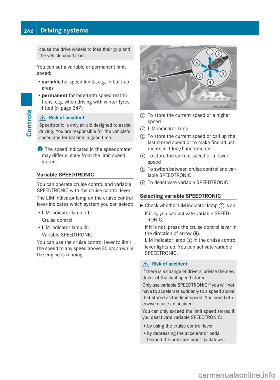
The LIM indicator lamp on the cruise control
lever indicates which system you can select:
R LIM indicator lamp off:
Cruise control
R LIM indicator lamp lit:
Variable SPEEDTRONIC
You can use the cruise control lever to limit
the speed to any speed above 30 km/h while
the engine is running. 0001
To store the current speed or a higher
speed
0002 LIM indicator lamp
0015 To store the current speed or call up the
last stored speed or to make fine adjust-
ments in 1 km/h increments
0014 To store the current speed or a lower
speed
0012 To switch between cruise control and var-
iable SPEEDTRONIC
0013 To deactivate variable SPEEDTRONIC
Selecting variable SPEEDTRONIC X
Check whether LIM indicator lamp 0002is on.
If it is, you can activate variable SPEED-
TRONIC.
If it is not, press the cruise control lever in
the direction of arrow 0012.
LIM indicator lamp 0002in the cruise control
lever lights up. You can activate variable
SPEEDTRONIC. G
Risk of accident
If there is a change of drivers, advise the new
driver of the limit speed stored.
Only use variable SPEEDTRONIC if you will not
have to accelerate suddenly to a speed above
that stored as the limit speed. You could oth-
erwise cause an accident.
You can only exceed the limit speed stored if
you deactivate variable SPEEDTRONIC:
R by using the cruise control lever
R by depressing the accelerator pedal
beyond the pressure point (kickdown) 246
Driving systemsControls
BA 197 ECE RE 2010/6a; 1; 2, en-GB
sabbaeu
Version: 3.0.3.6 2010-05-07T14:19:43+02:00 - Seite 246
Page 271 of 361
To avoid the risk of burns, only touch those
components described in the Owner's Manual
and observe the relevant safety notes. G
Risk of injury
The radiator fan between the radiator and the
engine can start automatically, even if the key
has been removed from the ignition lock. For
this reason, you must not reach into the fan
rotation area. Otherwise, you could be
injured.
The electronic ignition system uses high volt-
age. For this reason, you must never touch
ignition system components (ignition coil,
ignition cable, spark plug connector or test
socket) while:
R the engine is running.
R the engine is being started.
R the ignition is switched on and the engine
is being cranked by hand.
X Make sure that the windscreen wipers are
switched off. G
Risk of injury
The windscreen wipers and wiper linkage
could be set in motion.
When the bonnet is open, you or others could
be injured by the wiper linkage.
Make sure that the windscreen wipers are
switched off. Remove the key or make sure
that no ignition position has been selected
with KEYLESS-GO. All indicator lights must be
off in the instrument cluster.
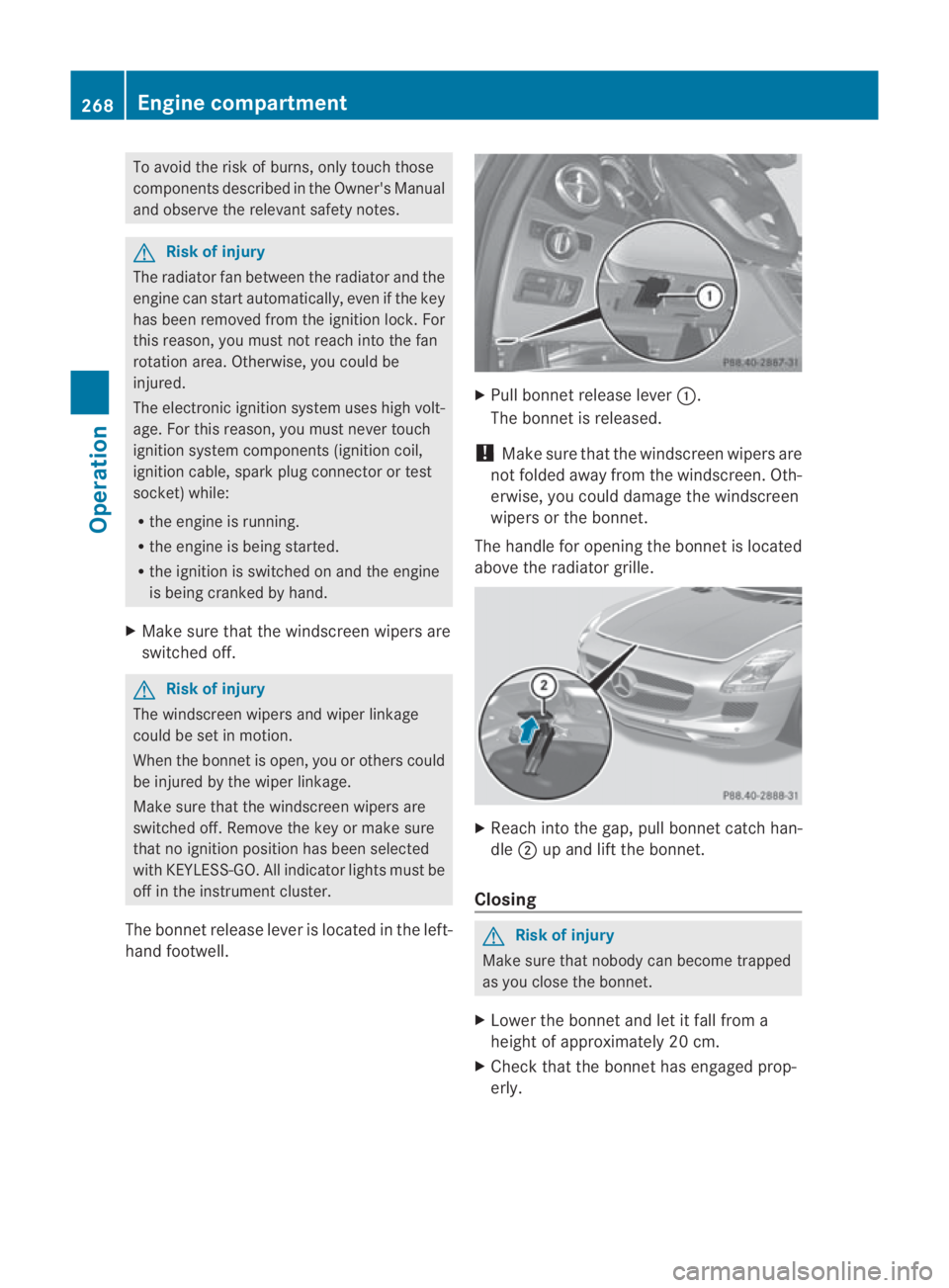
The bonnet release lever is located in the left-
hand footwell. X
Pull bonnet release lever 0001.
The bonnet is released.
! Make sure that the windscreen wipers are
not folded away from the windscreen .Oth-
erwise, you could damage the windscreen
wipers or the bonnet.
The handle for opening the bonnet is located
above the radiato rgrille. X
Reach into the gap, pull bonnet catch han-
dle 0002up and lift the bonnet.
Closing G
Risk of injury
Make sure that nobody can become trapped
as you close the bonnet.
X Lower the bonnet and let it fall from a
height of approximately 20 cm.
X Check that the bonnet has engaged prop-
erly. 268
Engine compartmentOperation
BA 197 ECE RE 2010/6a; 1; 2, en-GB
sabbaeu
Version: 3.0.3.6
2010-05-07T14:19:43+02:00 - Seite 268
Page 272 of 361
i
If the bonnet can be raised slightly, it is
not properly engaged. Open it again and
close it with a little more force. Engine oil
Depending on driving style, the vehicle con-
sumes a maximum of 0.8 l oil per 1000 km.
The oil consumption may be highert han this
when the vehicle is new or if you frequently
drive at high engine speeds.
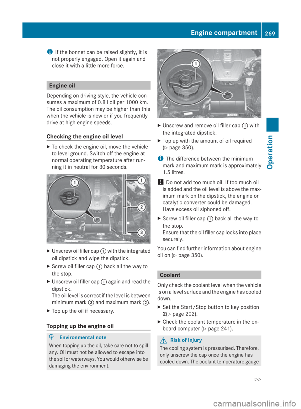
Checking the engine oil level X
To check the engine oil, move the vehicle
to level ground. Switch off the engine at
normal operating temperature after run-
ning it in neutral for 30 seconds. X
Unscrew oil filler cap 0001with the integrated
oil dipstick and wipe the dipstick.
X Screw oil filler cap 0001back all the way to
the stop.
X Unscrew oil filler cap 0001again and read the
dipstick.
The oil level is correct if the level is between
minimum mark 0015and maximum mark 0002.
X Top up the oil if necessary.
Topping up the engine oil H
Environmental note
When topping up the oil, take care not to spill
any. Oil must not be allowed to escape into
the soil or waterways. You would otherwise be
damaging the environment. X
Unscrew and remove oil filler cap 0001with
the integrated dipstick.
X Top up with the amount of oil required
(Y page 350).
i The difference between the minimum
mark and maximum mark is approximately
1.5 litres.
! Do not add too much oil. If too much oil
is added and the oil level is above the max-
imum mark on the dipstick, the engine or
catalytic converter could be damaged.
Have excess oil siphoned off.
X Screw oil filler cap 0001back all the way to
the stop.
Ensure that the oil filler cap locks into place
securely.
You can find further information about engine
oil on (Y page 350). Coolant
Only check the coolant level when the vehicle
is on a level surface and the engine has cooled
down.
X Set the Start/Stop button to key position
2(Y page 202).
X Check the coolant temperature in the on-
board computer (Y page 241). G
Risk of injury
The cooling system is pressurised. Therefore,
only unscrew the cap once the engine has
cooled down. The coolant temperature gauge Engine compartment
269Operation
BA 197 ECE RE 2010/6a; 1; 2, en-GB
sabbaeu Version: 3.0.3.6 2010-05-07T14:19:43+02:00 - Seite 269 Z
Page 279 of 361
obtained at a qualified specialist workshop,
e.g. from a Mercedes-Benz Service Centre.
Under these circumstances, you should also
restrict the maximum speed of the vehicle
using permanent SPEED-
TRONIC 19
(Y page 245) so that it does not
exceed the maximum permissible speed for
the winter tyres.
Once you have fitted the winter tyres:
X Check the tyre pressures (Y page 272).
X Restart the tyre pressure monitor
(Y page 273).
i Speeds of up to 240 km/h with winter
tyre variant 1: despite what is stated on the
tyre pressure information label (fuel filler
flap), for speeds up to 240 km/ha nd winter
tyre variant 1 (Y page 354), the tyre pres-
sures can be reduced:
R front −40 kPa (−0.4 bar)
R rear −60 kPa (−0.6 bar)
This improves the ride comfort of your vehi-
cle; however, the fuel consumption may
increase slightly. G
Ris
kofa ccident
If you fit the spare wheel* when driving with
winter tyres, bear in mind that driving stability
will be impaired owing to unstable cornering
characteristics caused by the differen ttyres.
You should therefore adapt your driving style
and drive carefully.
Have the spare wheel* replaced at the near-
est qualified specialist workshop which has
the necessary specialist knowledge and tools
to carry out the wor krequired. Mercedes-
Benz recommends that you use a Mercedes-
Benz Service Centre for this purpose. In par-
ticular, work relevant to safety or on safety-
related systems must be carried out at a quali-
fied specialist workshop. Snow chains
For safety reasons, Mercedes-Benz recom-
mends that you only use snow chains which
have been specially approved for your vehicle
by Mercedes-Benz, or are of a corresponding
standard of quality.
If you intend to fit snow chains, please bear
the following points in mind:
R snow chains cannot be fitted to all wheel/
tyre combinations.
R snow chains must not be fitted to emer-
gency spare wheels, e.g. Minispare.
R fit snow chains only in pairs and only to the
rear wheels. Observe the manufacturer's
installation instructions.
Do not exceed the maximum permissible
speed of 50 km/h.
i You may wish to deactivate ESP ®
when
pulling away with snow chains fitted
(Y page 47). This way you can allow the
wheels to spin in a controlled manner, ach-
ieving an increased driving force (cutting
action). Winter driving
G
Risk of accident
Do not shift down for additional engine brak-
ing on a slippery road surface. This could
cause the drive wheels to lose their grip and
the vehicle could skid.
You should drive particularly carefully on slip-
pery road surfaces. Avoid sudden accelera-
tion, steering and braking manoeuvres.
If the vehicle threatens to skid or cannot be
stopped when moving at low speed:
X Engage neutral.
X Try to bring the vehicle under control using
corrective steering.
19 Only available for certain countries. 276
Winter operationOperation
BA 197 ECE RE 2010/6a; 1; 2, en-GB
sabbaeu
Version: 3.0.3.6 2010-05-07T14:19:43+02:00 - Seite 276
Page 284 of 361
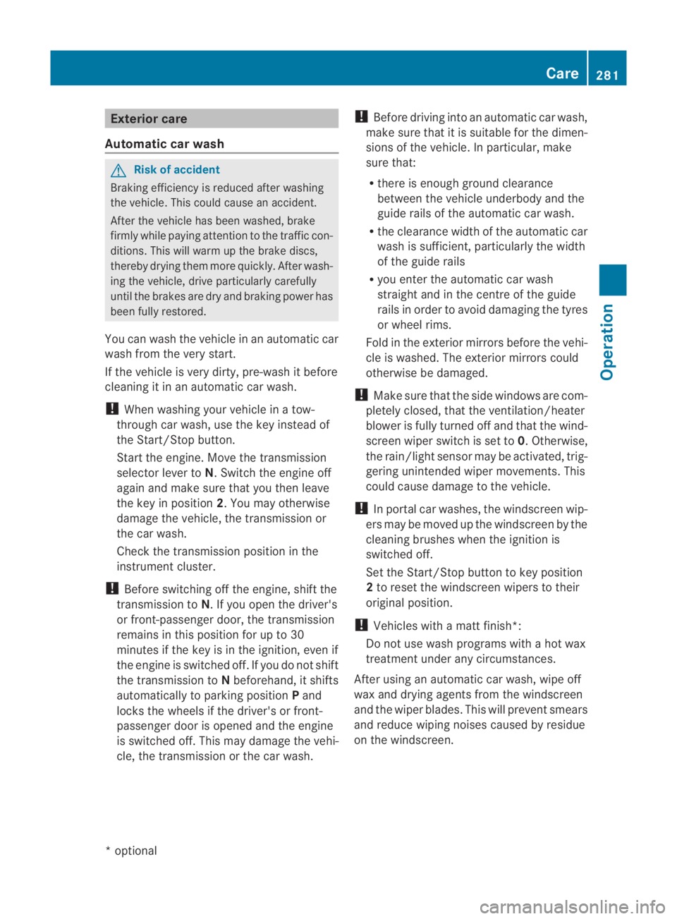
Exterio
rcare
Automatic car wash G
Risk of accident
Braking efficiency is reduced after washing
the vehicle. This could cause an accident.
After the vehicle has bee nwashed, brake
firmly while paying attention to the traffic con-
ditions. This will warm up the brake discs,
thereby drying them mor equickly. Afte rwash-
ing the vehicle, drive particularly carefully
until the brakes are dry and braking power has
been fully restored.
You can wash the vehicle in an automatic car
wash from the very start.
If the vehicle is very dirty, pre-wash it before
cleaning it in an automatic car wash.
! When washing your vehicle in a tow-
through car wash, use the key instead of
the Start/Stop button.
Start the engine .Move the transmission
selector lever to N. Switch the engine off
again and make sure that you then leave
the key in position 2.You may otherwise
damage the vehicle, the transmission or
the car wash.
Check the transmission position in the
instrument cluster.
! Before switching off the engine, shift the
transmission to N. If you open the driver's
or front-passenger door, the transmission
remains in this position for up to 30
minutes if the key is in the ignition, even if
the engine is switched off. If you do not shift
the transmission to Nbeforehand, it shifts
automatically to parking position Pand
locks the wheels if the driver's or front-
passenger door is opened and the engine
is switched off. This may damage the vehi-
cle, the transmission or the car wash. !
Before driving into an automatic car wash,
make sure that it is suitable for the dimen-
sions of the vehicle. In particular, make
sure that:
R there is enough ground clearance
between the vehicle underbody and the
guide rails of the automatic car wash.
R the clearance width of the automatic car
wash is sufficient, particularly the width
of the guide rails
R you enter the automatic car wash
straight and in the centre of the guide
rails in order to avoid damaging the tyres
or wheel rims.
Fold in the exterior mirrors before the vehi-
cle is washed. The exterior mirrors could
otherwise be damaged.
! Make sure that the side windows are com-
pletely closed, that the ventilation/heater
blower is fully turned off and that the wind-
screen wiper switch is set to 0.Otherwise,
the rain/light senso rmay be activated, trig-
gering unintended wiper movements. This
could cause damage to the vehicle.
! In portal car washes, the windscree nwip-
ers may be moved up the windscreen by the
cleaning brushes when the ignition is
switched off.
Set the Start/Stop button to key position
2 to reset the windscreen wipers to their
original position.
! Vehicles with a mat tfinish*:
Do not use wash programs with a hot wax
treatment under any circumstances.
After using an automatic car wash, wipe off
wax and drying agents fro mthe windscreen
and the wiper blades. This will prevent smears
and reduce wiping noises caused by residue
on the windscreen. Care
281Operation
*optional
BA 197 ECE RE 2010/6a; 1; 2, en-GB
sabbaeu
Version: 3.0.3.6 2010-05-07T14:19:43+02:00 - Seite 281 Z
Page 298 of 361
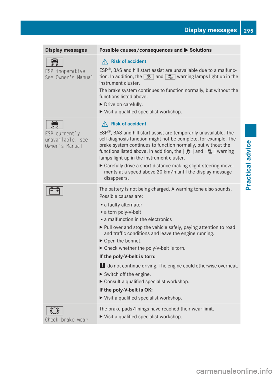
Display messages Possible causes/consequences and
0003 Solutions
0011
ESP inoperative
See Owner's Manual G
Risk of accident
ESP ®
, BA Sand hill start assist are unavailable due to amalfunc-
tion. In addition, the 0002and0001 warning lamps light up in the
instrument cluster.
The brake system continue sto function normally, but without the
functions listed above.
X Drive on carefully.
X Visit a qualified specialist workshop. 0011
ESP currently
unavailable, see
Owner's Manual G
Risk of accident
ESP ®
, BAS and hill start assist are temporarily unavailable. The
self-diagnosis function might not be complete, for example. The
brake system continues to function normally, but without the
functions listed above. In addition, the 0002and0001 warning
lamps light up in the instrument cluster.
X Carefully drive a short distance making slight steering move-
ments at a speed above 20 km/h until the display message
disappears. 000D The battery is not being charged.
Awarning tone also sounds.
Possible causes are:
R a faulty alternator
R a torn poly-V-belt
R a malfunction in the electronics
X Pull ove rand stop the vehicle safely, paying attentio nto road
and traffic conditions and leave the engine running.
X Open the bonnet.
X Check whether the poly-V-belt is torn.
If the poly-V-belt is torn:
! do not continue driving. The engine could otherwise overheat.
X Switch off the engine.
X Consult a qualified specialist workshop.
If the poly-V-belt is OK:
X Visit a qualified specialist workshop. 0006
Check brake wear The brake pads/linings have reached their wear limit.
X
Visit a qualified specialist workshop. Display messages
295Practical advice
BA 197 ECE RE 2010/6a; 1; 2, en-GB
sabbaeu Version: 3.0.3.6 2010-05-07T14:19:43+02:00 - Seite 295 Z