warning MERCEDES-BENZ SPRINTER 2005 Service Repair Manual
[x] Cancel search | Manufacturer: MERCEDES-BENZ, Model Year: 2005, Model line: SPRINTER, Model: MERCEDES-BENZ SPRINTER 2005Pages: 1232, PDF Size: 39.23 MB
Page 1187 of 1232
WARNING: REVIEW THE WARNINGS AND CAU-
TIONS IN THE FRONT OF THIS SECTION BEFORE
PERFORMING THE FOLLOWING OPERATION (Refer
to 24 - HEATING & AIR CONDITIONING/PLUMBING -
WARNING) and (Refer to 24 - HEATING & AIR CON-
DITIONING/PLUMBING - CAUTION).
FRONT SECTION
(1) Recover the refrigerant from the refrigerant
system (Refer to 24 - HEATING & AIR CONDITION-
ING/PLUMBING - STANDARD PROCEDURE).
(2) Disconnect and isolate the battery negative
cable.
(3) Remove the grille (Refer to 23 - BODY/EXTE-
RIOR/GRILLE - REMOVAL).
(4) Remove the nut that secures the liquid line fit-
ting to the condenser outlet port on the left side of
condenser.
(5) Disconnect the liquid line fitting from the con-
denser outlet port.
(6) Remove the seal from the liquid line fitting and
discard.
(7) Install plug in, or tape over the opened liquid
line fitting and the condenser outlet port.
(8) Remove the routing clip retaining nut and dis-
engage the routing clip retainer on top of the left
frame rail from the front section of the liquid line.
(9) Remove the A/C pressure sensor from the front
liquid line fitting (Refer to 24 - HEATING & AIR
CONDITIONING/CONTROLS/A/C PRESSURE
TRANSDUCER - REMOVAL).
(10) Remove the bolt that secures the front section
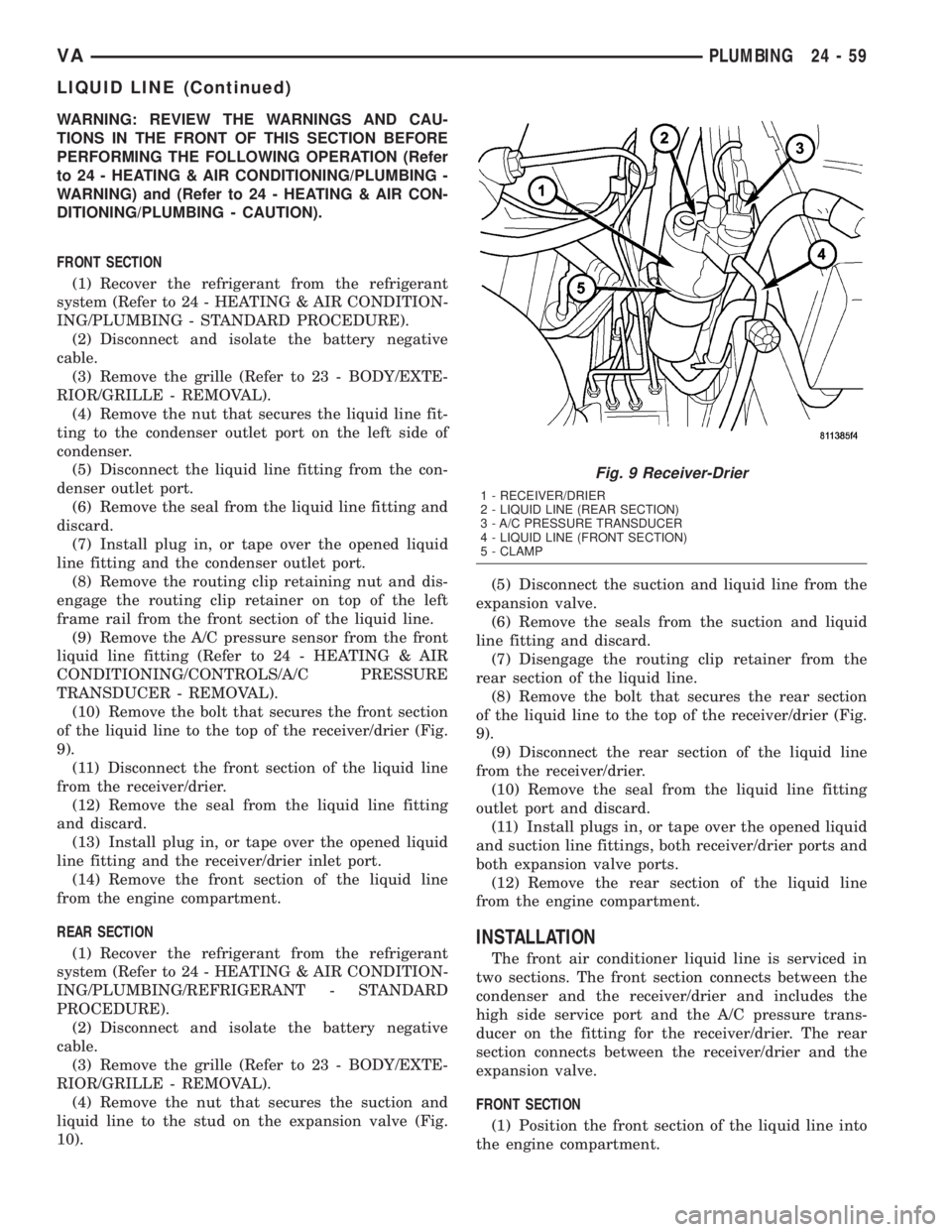
of the liquid line to the top of the receiver/drier (Fig.
9).
(11) Disconnect the front section of the liquid line
from the receiver/drier.
(12) Remove the seal from the liquid line fitting
and discard.
(13) Install plug in, or tape over the opened liquid
line fitting and the receiver/drier inlet port.
(14) Remove the front section of the liquid line
from the engine compartment.
REAR SECTION
(1) Recover the refrigerant from the refrigerant
system (Refer to 24 - HEATING & AIR CONDITION-
ING/PLUMBING/REFRIGERANT - STANDARD
PROCEDURE).
(2) Disconnect and isolate the battery negative
cable.
(3) Remove the grille (Refer to 23 - BODY/EXTE-
RIOR/GRILLE - REMOVAL).
(4) Remove the nut that secures the suction and
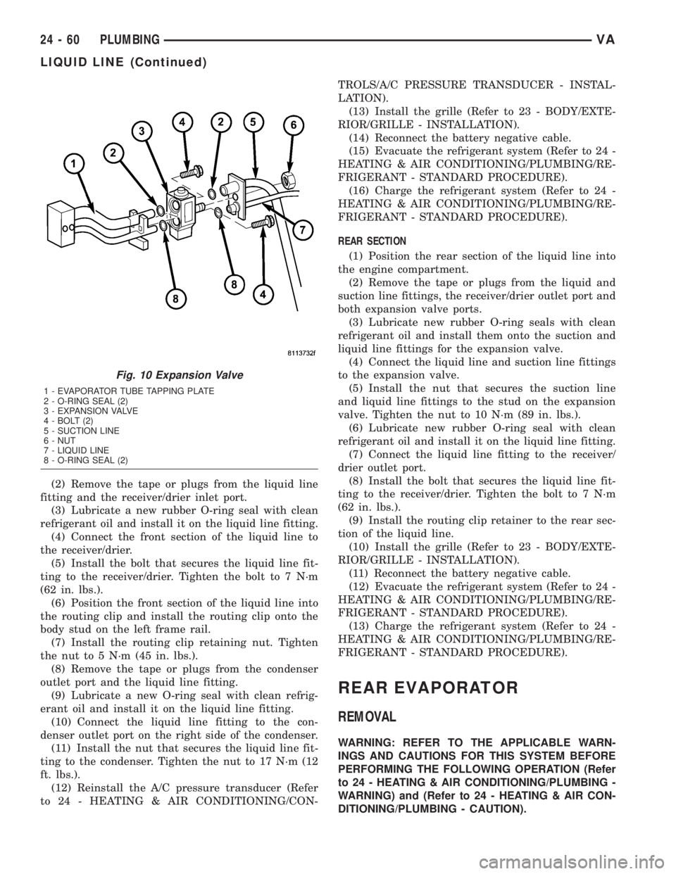
liquid line to the stud on the expansion valve (Fig.
10).(5) Disconnect the suction and liquid line from the
expansion valve.
(6) Remove the seals from the suction and liquid
line fitting and discard.
(7) Disengage the routing clip retainer from the
rear section of the liquid line.
(8) Remove the bolt that secures the rear section
of the liquid line to the top of the receiver/drier (Fig.
9).
(9) Disconnect the rear section of the liquid line
from the receiver/drier.
(10) Remove the seal from the liquid line fitting
outlet port and discard.
(11) Install plugs in, or tape over the opened liquid
and suction line fittings, both receiver/drier ports and
both expansion valve ports.
(12) Remove the rear section of the liquid line
from the engine compartment.
INSTALLATION
The front air conditioner liquid line is serviced in
two sections. The front section connects between the
condenser and the receiver/drier and includes the
high side service port and the A/C pressure trans-
ducer on the fitting for the receiver/drier. The rear
section connects between the receiver/drier and the
expansion valve.
FRONT SECTION
(1) Position the front section of the liquid line into
the engine compartment.
Fig. 9 Receiver-Drier
1 - RECEIVER/DRIER
2 - LIQUID LINE (REAR SECTION)
3 - A/C PRESSURE TRANSDUCER
4 - LIQUID LINE (FRONT SECTION)
5 - CLAMP
VAPLUMBING 24 - 59
LIQUID LINE (Continued)
Page 1188 of 1232
(2) Remove the tape or plugs from the liquid line
fitting and the receiver/drier inlet port.
(3) Lubricate a new rubber O-ring seal with clean
refrigerant oil and install it on the liquid line fitting.
(4) Connect the front section of the liquid line to
the receiver/drier.
(5) Install the bolt that secures the liquid line fit-
ting to the receiver/drier. Tighten the bolt to 7 N´m
(62 in. lbs.).
(6) Position the front section of the liquid line into
the routing clip and install the routing clip onto the
body stud on the left frame rail.
(7) Install the routing clip retaining nut. Tighten
the nut to 5 N´m (45 in. lbs.).
(8) Remove the tape or plugs from the condenser
outlet port and the liquid line fitting.
(9) Lubricate a new O-ring seal with clean refrig-
erant oil and install it on the liquid line fitting.
(10) Connect the liquid line fitting to the con-
denser outlet port on the right side of the condenser.
(11) Install the nut that secures the liquid line fit-
ting to the condenser. Tighten the nut to 17 N´m (12
ft. lbs.).
(12) Reinstall the A/C pressure transducer (Refer
to 24 - HEATING & AIR CONDITIONING/CON-TROLS/A/C PRESSURE TRANSDUCER - INSTAL-
LATION).
(13) Install the grille (Refer to 23 - BODY/EXTE-
RIOR/GRILLE - INSTALLATION).
(14) Reconnect the battery negative cable.
(15) Evacuate the refrigerant system (Refer to 24 -
HEATING & AIR CONDITIONING/PLUMBING/RE-
FRIGERANT - STANDARD PROCEDURE).
(16) Charge the refrigerant system (Refer to 24 -
HEATING & AIR CONDITIONING/PLUMBING/RE-
FRIGERANT - STANDARD PROCEDURE).
REAR SECTION
(1) Position the rear section of the liquid line into
the engine compartment.
(2) Remove the tape or plugs from the liquid and
suction line fittings, the receiver/drier outlet port and
both expansion valve ports.
(3) Lubricate new rubber O-ring seals with clean
refrigerant oil and install them onto the suction and
liquid line fittings for the expansion valve.
(4) Connect the liquid line and suction line fittings
to the expansion valve.
(5) Install the nut that secures the suction line
and liquid line fittings to the stud on the expansion
valve. Tighten the nut to 10 N´m (89 in. lbs.).
(6) Lubricate new rubber O-ring seal with clean
refrigerant oil and install it on the liquid line fitting.
(7) Connect the liquid line fitting to the receiver/
drier outlet port.
(8) Install the bolt that secures the liquid line fit-
ting to the receiver/drier. Tighten the bolt to 7 N´m
(62 in. lbs.).
(9) Install the routing clip retainer to the rear sec-
tion of the liquid line.
(10) Install the grille (Refer to 23 - BODY/EXTE-
RIOR/GRILLE - INSTALLATION).
(11) Reconnect the battery negative cable.
(12) Evacuate the refrigerant system (Refer to 24 -
HEATING & AIR CONDITIONING/PLUMBING/RE-
FRIGERANT - STANDARD PROCEDURE).
(13) Charge the refrigerant system (Refer to 24 -
HEATING & AIR CONDITIONING/PLUMBING/RE-
FRIGERANT - STANDARD PROCEDURE).
REAR EVAPORATOR
REMOVAL
WARNING: REFER TO THE APPLICABLE WARN-
INGS AND CAUTIONS FOR THIS SYSTEM BEFORE
PERFORMING THE FOLLOWING OPERATION (Refer
to 24 - HEATING & AIR CONDITIONING/PLUMBING -
WARNING) and (Refer to 24 - HEATING & AIR CON-
DITIONING/PLUMBING - CAUTION).
Fig. 10 Expansion Valve
1 - EVAPORATOR TUBE TAPPING PLATE
2 - O-RING SEAL (2)
3 - EXPANSION VALVE
4 - BOLT (2)
5 - SUCTION LINE
6 - NUT
7 - LIQUID LINE
8 - O-RING SEAL (2)
24 - 60 PLUMBINGVA
LIQUID LINE (Continued)
Page 1190 of 1232
(11) Remove the tape or plug from the liquid line
fittings and the solenoid valve outlet port and the
expansion valve inlet port.
(12) Lubricate new rubber o-ring seals with clean
refrigerant oil and install them on the liquid line fit-
tings.
(13) Install the liquid line between the rear expan-
sion valve and the solenoid valve.
(14) Install and tighten the nuts that secures the
liquid line fittings to the rear expansion valve and
solenoid valve. Tighten the nuts to 16 N´m (142 in.
lbs.).
(15) Install the rear A/C housing (Refer to 24 -
HEATING & AIR CONDITIONING/DISTRIBUTION/
REAR A/C HEATER HOUSING - INSTALLATION).
NOTE: If the evaporator is being replaced, add 30
milliliters (1 fluid ounce) of refrigerant oil to the
refrigerant system.
REAR EXPANSION VALVE
REMOVAL
WARNING: REFER TO THE APPLICABLE WARN-
INGS AND CAUTIONS FOR THIS SYSTEM BEFORE
PERFORMING THE FOLLOWING OPERATION (Refer
to 24 - HEATING & AIR CONDITIONING/PLUMBING -
WARNING) and (Refer to 24 - HEATING & AIR CON-
DITIONING/PLUMBING - CAUTION).
(1) Recover the refrigerant from the A/C system
(Refer to 24 - HEATING & AIR CONDITIONING/
PLUMBING - STANDARD PROCEDURE).
(2) Disconnect and isolate the battery negative
cable.
(3) Remove the rear dome light from the rear roof
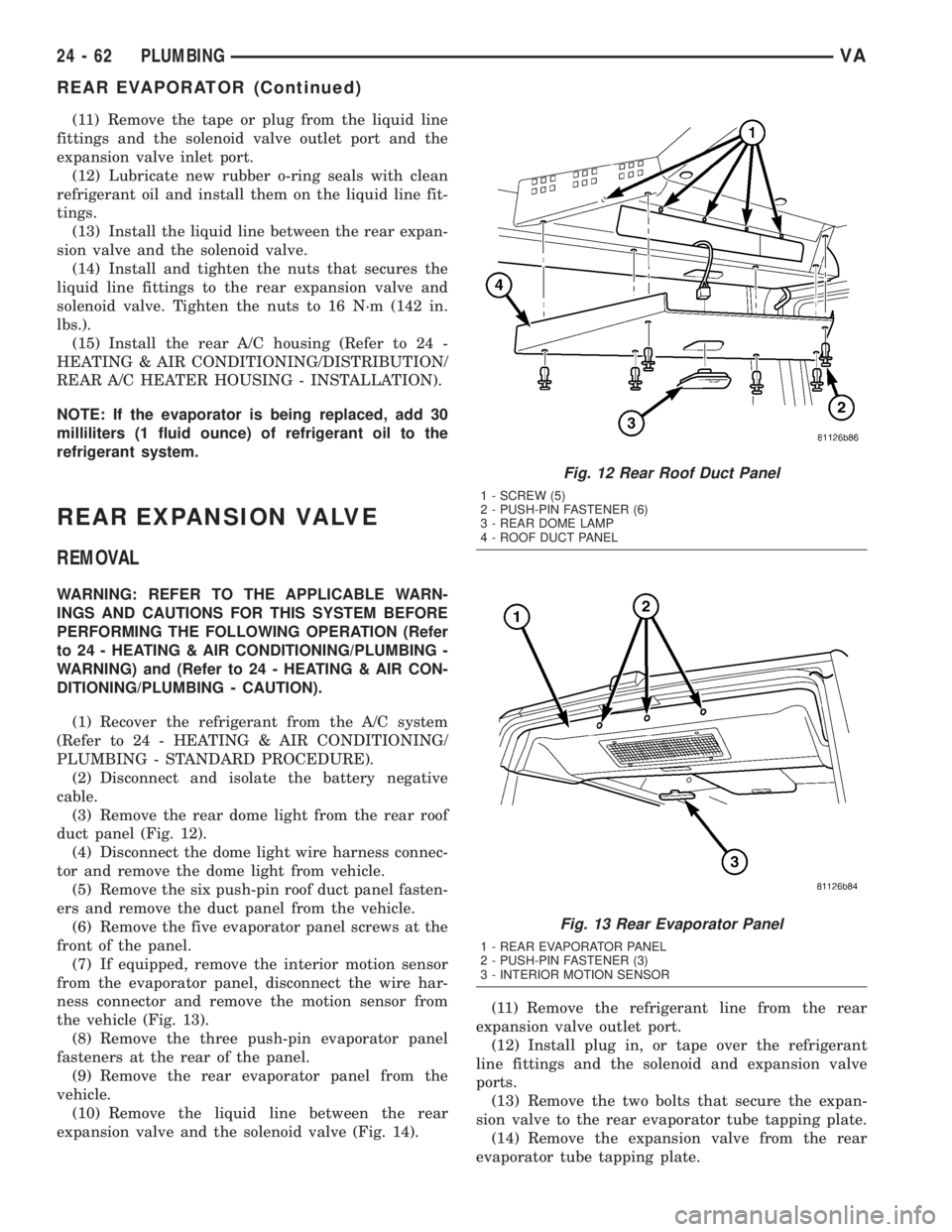
duct panel (Fig. 12).
(4) Disconnect the dome light wire harness connec-
tor and remove the dome light from vehicle.
(5) Remove the six push-pin roof duct panel fasten-
ers and remove the duct panel from the vehicle.
(6) Remove the five evaporator panel screws at the
front of the panel.
(7) If equipped, remove the interior motion sensor
from the evaporator panel, disconnect the wire har-
ness connector and remove the motion sensor from
the vehicle (Fig. 13).
(8) Remove the three push-pin evaporator panel
fasteners at the rear of the panel.
(9) Remove the rear evaporator panel from the
vehicle.
(10) Remove the liquid line between the rear
expansion valve and the solenoid valve (Fig. 14).(11) Remove the refrigerant line from the rear
expansion valve outlet port.
(12) Install plug in, or tape over the refrigerant
line fittings and the solenoid and expansion valve
ports.
(13) Remove the two bolts that secure the expan-
sion valve to the rear evaporator tube tapping plate.
(14) Remove the expansion valve from the rear
evaporator tube tapping plate.
Fig. 12 Rear Roof Duct Panel
1 - SCREW (5)
2 - PUSH-PIN FASTENER (6)
3 - REAR DOME LAMP
4 - ROOF DUCT PANEL
Fig. 13 Rear Evaporator Panel
1 - REAR EVAPORATOR PANEL
2 - PUSH-PIN FASTENER (3)
3 - INTERIOR MOTION SENSOR
24 - 62 PLUMBINGVA
REAR EVAPORATOR (Continued)
Page 1192 of 1232
RECEIVER/DRIER
DESCRIPTION
The receiver/drier is mounted in a bracket secured
to the left front strut tower in the engine compart-
ment. The receiver/drier is connected between the
front and rear sections of the liquid line between the
condenser outlet and the evaporator inlet. The receiv-
er/drier cannot be repaired. If the receiver/drier is
faulty or damaged, or if the refrigerant system has
been contaminated or left open to the atmosphere for
an indeterminable period or if the compressor has
failed, it must be replaced.
OPERATION
The receiver/drier performs a filtering action to
prevent foreign material in the refrigerant from con-
taminating the expansion valve. A desiccant bag is
mounted inside the receiver/drier canister to absorb
any moisture which may have entered and become
trapped within the refrigerant system. In addition,
during periods of high demand air conditioner opera-
tion, the receiver/drier acts as a reservoir to store
surplus refrigerant. Refrigerant enters the receiver/
drier as a high-pressure, low-temperature liquid.
REMOVAL
WARNING: REVIEW THE WARNINGS AND CAU-
TIONS IN THE FRONT OF THIS SECTION BEFORE
PERFORMING THE FOLLOWING OPERATION (Refer
to 24 - HEATING & AIR CONDITIONING/PLUMBING -
WARNING) and (Refer to 24 - HEATING & AIR CON-
DITIONING/PLUMBING - CAUTION).
(1) Recover the refrigerant from the refrigerant
system(Refer to 24 - HEATING & AIR CONDITION-
ING/PLUMBING - STANDARD PROCEDURE).
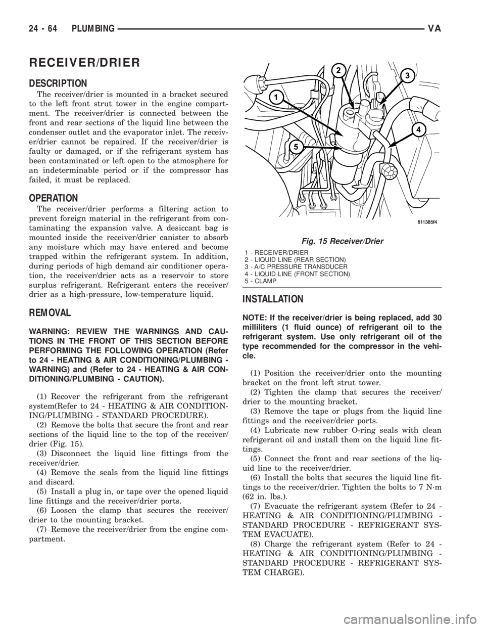
(2) Remove the bolts that secure the front and rear
sections of the liquid line to the top of the receiver/
drier (Fig. 15).
(3) Disconnect the liquid line fittings from the
receiver/drier.
(4) Remove the seals from the liquid line fittings
and discard.
(5) Install a plug in, or tape over the opened liquid
line fittings and the receiver/drier ports.
(6) Loosen the clamp that secures the receiver/
drier to the mounting bracket.
(7) Remove the receiver/drier from the engine com-
partment.
INSTALLATION
NOTE: If the receiver/drier is being replaced, add 30
milliliters (1 fluid ounce) of refrigerant oil to the
refrigerant system. Use only refrigerant oil of the
type recommended for the compressor in the vehi-
cle.
(1) Position the receiver/drier onto the mounting
bracket on the front left strut tower.
(2) Tighten the clamp that secures the receiver/
drier to the mounting bracket.
(3) Remove the tape or plugs from the liquid line
fittings and the receiver/drier ports.
(4) Lubricate new rubber O-ring seals with clean
refrigerant oil and install them on the liquid line fit-
tings.
(5) Connect the front and rear sections of the liq-
uid line to the receiver/drier.
(6) Install the bolts that secures the liquid line fit-
tings to the receiver/drier. Tighten the bolts to 7 N´m
(62 in. lbs.).
(7) Evacuate the refrigerant system (Refer to 24 -
HEATING & AIR CONDITIONING/PLUMBING -
STANDARD PROCEDURE - REFRIGERANT SYS-
TEM EVACUATE).
(8) Charge the refrigerant system (Refer to 24 -
HEATING & AIR CONDITIONING/PLUMBING -
STANDARD PROCEDURE - REFRIGERANT SYS-
TEM CHARGE).
Fig. 15 Receiver/Drier
1 - RECEIVER/DRIER
2 - LIQUID LINE (REAR SECTION)
3 - A/C PRESSURE TRANSDUCER
4 - LIQUID LINE (FRONT SECTION)
5 - CLAMP
24 - 64 PLUMBINGVA
Page 1194 of 1232

REFRIGERANT OIL CAPACITIES
Component ml fl oz
Total System Fill410 (425
w/rear A/C)13.9 (14.4
w/rear A/C
Receiver/Drier 30 1.0
Condenser 30 1.0
Front Evaporator 60 2.0
Rear Evaporator 30 1.0
CompressorDrain and measure the oil
from the old compressor -
see text.
SUCTION LINE
REMOVAL
WARNING: REVIEW THE WARNINGS AND CAU-
TIONS IN THE FRONT OF THIS SECTION BEFORE
PERFORMING THE FOLLOWING OPERATION (Refer
to 24 - HEATING & AIR CONDITIONING/PLUMBING -
WARNING) and (Refer to 24 - HEATING & AIR CON-
DITIONING/PLUMBING - CAUTION).
(1) Recover the refrigerant system. (Refer to 24 -
HEATING & AIR CONDITIONING/PLUMBING -
STANDARD PROCEDURE - REFRIGERANT
RECOVERY)
(2) Disconnect and isolate the negative battery
cable.
(3) Remove the routing clip retaining nut and dis-
engage the metal routing clip from the suction line.
(4) Disengage the plastic routing clip located near
the expansion valve from the suction line.
(5) Remove the nut that secures the suction and
liquid line fittings to the stud on the expansion valve
(Fig. 16).
(6) Disconnect the suction and liquid lines from
the expansion valve.
(7) Remove the seals from the suction and liquid
line fitting and discard.
(8) Install plugs in, or tape over the opened liquid
and suction line fittings and both expansion valve
ports.
(9) Remove the bolt that secures the suction line
fitting to the top of the compressor (Fig. 17).
(10) Disconnect the suction line fitting from the
compressor suction port.
(11) Remove the O-ring seal from the suction line
fitting and discard.
(12) Install plugs in, or tape over the opened suc-
tion line fitting and the compressor suction port.
(13) Remove the suction line from the vehicle.
INSTALLATION
(1) Position the suction line into the engine com-
partment.
(2) Remove plugs or tape from the suction line fit-
ting and the compressor suction port.
(3) Lubricate a new rubber O-ring seal with clean
refrigerant oil and install it onto the suction line fit-
ting.
(4) Connect the suction line fitting to the compres-
sor suction port.
(5) Install the bolt that secures the suction line fit-
ting to the top of the compressor. Tighten the bolt to
23 N´m (17 ft. lbs.).
(6) Remove the tape or plugs from the liquid and
suction line fittings and both expansion valve ports.
(7) Lubricate new rubber O-ring seals with clean
refrigerant oil and install them on the liquid and suc-
tion line fittings.
(8) Reconnect the liquid line fitting to the expan-
sion valve.
(9) Reconnect the suction line fitting to the expan-
sion valve.
(10) Install the nut that secures the suction line
and liquid line fittings to the stud on the expansion
valve. Tighten the nut to 10 N´m (89 in. lbs.).
Fig. 16 Expansion Valve
1 - EVAPORATOR TUBE TAPPING PLATE
2 - O-RING SEAL (2)
3 - EXPANSION VALVE
4 - BOLT (2)
5 - SUCTION LINE
6 - NUT
7 - LIQUID LINE
8 - O-RING SEAL (2)
24 - 66 PLUMBINGVA
REFRIGERANT OIL (Continued)
Page 1196 of 1232

(7) Connect the wire harness connector to the
heater water valve.
(8) Reconnect the battery negative cable.
(9) Fill the cooling system (Refer to 7 - COOLING/
ENGINE/COOLANT - STANDARD PROCEDURE).
UNDERBODY LINES
REMOVAL
The rear refrigerant lines for the optional rear A/C
system is serviced in four sections. The liquid line for
the optional rear A/C system uses a spring-lock
refrigerant line coupler which requires the use of a
3/8 inch quick-disconnect tool (part of Special Tool,
A/C Line Disconnect Kit 7193).
WARNING: REVIEW THE WARNINGS AND CAU-
TIONS IN THE FRONT OF THIS SECTION BEFORE
PERFORMING THE FOLLOWING OPERATION (Refer
to 24 - HEATING & AIR CONDITIONING/PLUMBING -
WARNING) and (Refer to 24 - HEATING & AIR CON-
DITIONING/PLUMBING - CAUTION).
FRONT LIQUID LINE
(1) Recover the refrigerant from the refrigerant
system (Refer to 24 - HEATING & AIR CONDITION-
ING/PLUMBING - STANDARD PROCEDURE).
(2) Disconnect and isolate the battery negative
cable.
(3) Disconnect the rear section of the front liquid
line from the receiver-drier and the evaporator (Refer
to 24 - HEATING & AIR CONDITIONING/PLUMB-
ING/LIQUID LINE - REMOVAL).
(4) Disconnect the fitting to the intermediate liq-
uid line using Special Tool, A/C Line Disconnect Kit
7193.
(5) Remove the seals from the liquid line fittings
and discard.
(6) Install plug in, or tape over the open liquid line
fittings, the reciever-drier outlet port and the expan-
sion valve ports.
(7) Remove the front liquid line from the engine
compartment.
FRONT SUCTION LINE
(1) Recover the refrigerant from the refrigerant
system (Refer to 24 - HEATING & AIR CONDITION-
ING/PLUMBING - STANDARD PROCEDURE).
(2) Disconnect and isolate the battery negative
cable.
(3) Remove the nut that secures the intermediate
suction line fitting to the stud on the front suction
line tapping plate.
(4) Disconnect the intermediate suction line fitting
from the front suction line tapping plate.(5) Install plug in, or tape over the open suction
line fitting and the front suction line tapping plate
inlet port.
(6) Disconnect the front suction line from the com-
pressor and front evaporator valve (Refer to 24 -
HEATING & AIR CONDITIONING/PLUMBING/
SUCTION LINE - REMOVAL).
(7) Remove the seals from the open suction line fit-
tings and discard.
(8) Install plug in, or tape over the open suction
line fittings, the compressor inlet port and the expan-
sion valve ports.
(9) Remove the front suction line from the engine
compartment.
(10) If necessary, remove the bolt that secures the
compressor portion of the front suction line to the
front suction line tapping plate, separate the front
suction lines, remove and discard the seal and, plug
in, or tape over the open suction line fittings.
INTERMEDIATE REFRIGERANT LINES
(1) Recover the refrigerant from the refrigerant
system (Refer to 24 - HEATING & AIR CONDITION-
ING/PLUMBING/REFRIGERANT - STANDARD
PROCEDURE).
(2) Disconnect and isolate the battery negative
cable.
(3) Disconnect the intermediate liquid line from
the front liquid line using Special Tool, A/C Line Dis-
connect Kit 7193.
(4) Remove the nut that secures the intermediate
suction line fitting to the stud on the front suction
line tapping plate.
(5) Disconnect the intermediate suction line from
the front suction line tapping plate.
(6) Remove the seals from the liquid and suction
line fittings and discard.
(7) Install plug in, or tape over the open suction
and liquid line fittings and the front suction line tap-
ping plate inlet port.
(8) Raise and support the vehicle.
(9) Disconnect the fittings that secure the interme-
diate refrigerant lines to the rear refrigerant lines.
(10) Remove the seals from the open liquid and
suction line fittings and discard.
(11) Install plugs in, or tape over the open liquid
and suction line fittings.
(12) Remove the bolts that secure the two interme-
diate refrigerant line retaining blocks to the vehicle
underbody.
(13) Remove the intermediate section of the rear
refrigerant lines from the vehicle underbody.
REAR REFRIGERANT LINES
(1) Recover the refrigerant from the refrigerant
system (Refer to 24 - HEATING & AIR CONDITION-
24 - 68 PLUMBINGVA
WATER VALVE (Continued)
Page 1201 of 1232
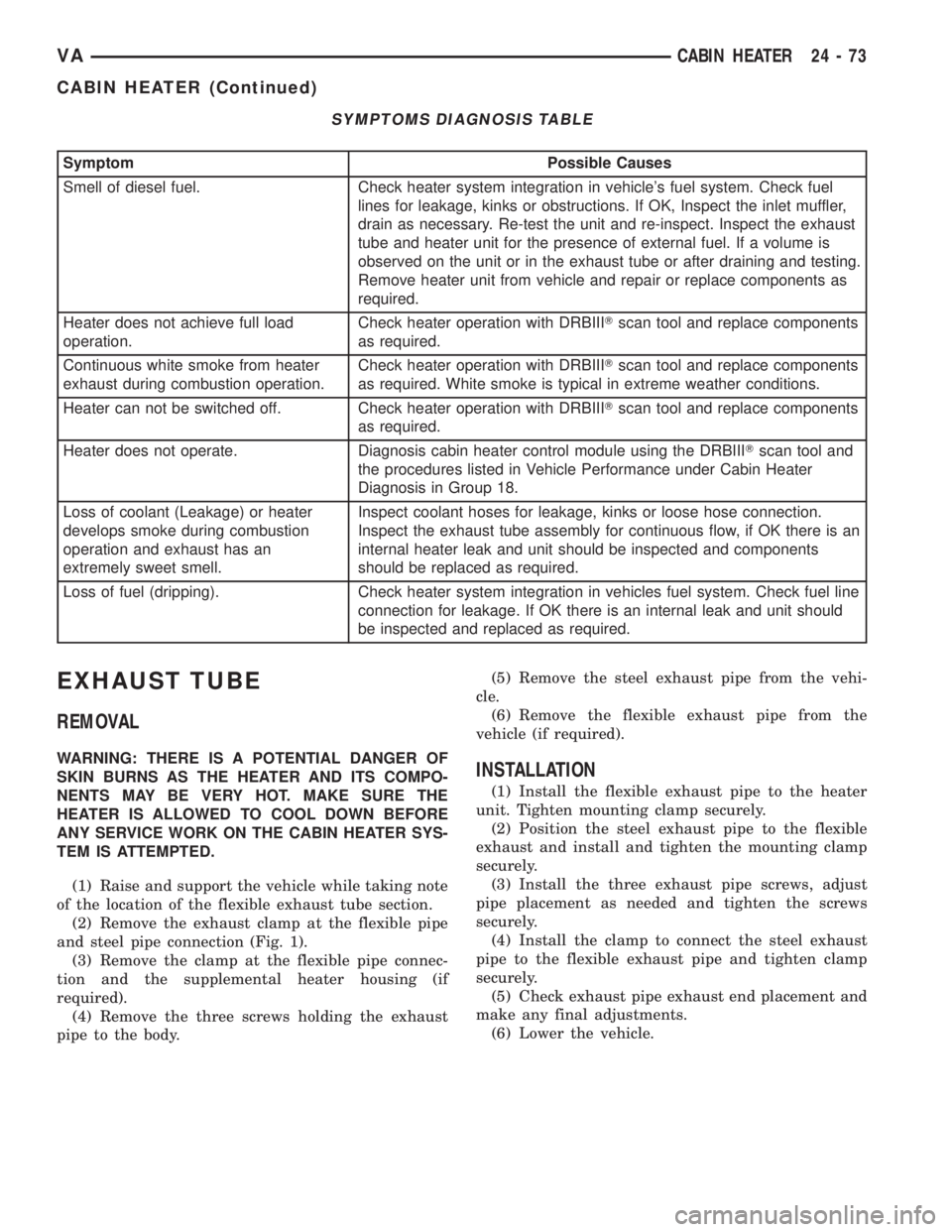
SYMPTOMS DIAGNOSIS TABLE
Symptom Possible Causes
Smell of diesel fuel. Check heater system integration in vehicle's fuel system. Check fuel
lines for leakage, kinks or obstructions. If OK, Inspect the inlet muffler,
drain as necessary. Re-test the unit and re-inspect. Inspect the exhaust
tube and heater unit for the presence of external fuel. If a volume is
observed on the unit or in the exhaust tube or after draining and testing.
Remove heater unit from vehicle and repair or replace components as
required.
Heater does not achieve full load
operation.Check heater operation with DRBIIITscan tool and replace components
as required.
Continuous white smoke from heater
exhaust during combustion operation.Check heater operation with DRBIIITscan tool and replace components
as required. White smoke is typical in extreme weather conditions.
Heater can not be switched off. Check heater operation with DRBIIITscan tool and replace components
as required.
Heater does not operate. Diagnosis cabin heater control module using the DRBIIITscan tool and
the procedures listed in Vehicle Performance under Cabin Heater
Diagnosis in Group 18.
Loss of coolant (Leakage) or heater
develops smoke during combustion
operation and exhaust has an
extremely sweet smell.Inspect coolant hoses for leakage, kinks or loose hose connection.
Inspect the exhaust tube assembly for continuous flow, if OK there is an
internal heater leak and unit should be inspected and components
should be replaced as required.
Loss of fuel (dripping). Check heater system integration in vehicles fuel system. Check fuel line
connection for leakage. If OK there is an internal leak and unit should
be inspected and replaced as required.
EXHAUST TUBE
REMOVAL
WARNING: THERE IS A POTENTIAL DANGER OF
SKIN BURNS AS THE HEATER AND ITS COMPO-
NENTS MAY BE VERY HOT. MAKE SURE THE
HEATER IS ALLOWED TO COOL DOWN BEFORE
ANY SERVICE WORK ON THE CABIN HEATER SYS-
TEM IS ATTEMPTED.
(1) Raise and support the vehicle while taking note
of the location of the flexible exhaust tube section.
(2) Remove the exhaust clamp at the flexible pipe
and steel pipe connection (Fig. 1).
(3) Remove the clamp at the flexible pipe connec-
tion and the supplemental heater housing (if
required).
(4) Remove the three screws holding the exhaust
pipe to the body.(5) Remove the steel exhaust pipe from the vehi-
cle.
(6) Remove the flexible exhaust pipe from the
vehicle (if required).INSTALLATION
(1) Install the flexible exhaust pipe to the heater
unit. Tighten mounting clamp securely.
(2) Position the steel exhaust pipe to the flexible
exhaust and install and tighten the mounting clamp
securely.
(3) Install the three exhaust pipe screws, adjust
pipe placement as needed and tighten the screws
securely.
(4) Install the clamp to connect the steel exhaust
pipe to the flexible exhaust pipe and tighten clamp
securely.
(5) Check exhaust pipe exhaust end placement and
make any final adjustments.
(6) Lower the vehicle.
VACABIN HEATER 24 - 73
CABIN HEATER (Continued)
Page 1204 of 1232
INSTALLATION
WARNING: DO NOT OPERATE THE DCHA IN AN
ENCLOSED AREA SUCH AS A GARAGE THAT
DOES NOT HAVE EXHAUST VENTILATION FACILI-
TIES. ALWAYS VENT THE DCHA'S EXHAUST WHEN
OPERATING THE DCHA. FAILURE TO FOLLOW
THESE INSTRUCTIONS MAY RESULT IN PERSONAL
INJURY OR DEATH.
WARNING: ALLOW THE DCHA ASSEMBLY TO
COOL BEFORE PERFORMING A COMPONENT
INSPECTION/REPAIR/REPLACEMENT. FAILURE TO
FOLLOW THESE INSTRUCTIONS MAY RESULT IN
PERSONAL INJURY.
WARNING: VERIFY THAT ALL DCHA FUEL LINES
ARE SECURELY FASTENED TO THEIR RESPECTIVE
COMPONENTS BEFORE PERFORMING THIS PRO-
CEDURE.
NOTE: Verify that there is more than 1/8 of a tank of
fuel in the vehicle's fuel tank before performing this
procedure. Add fuel, if necessary.(1) Install the heater fuel supply line into vehicle
and fuel line retainers.
(2) Install the fuel line connection at the fuel tank
and tighten the connection securely.
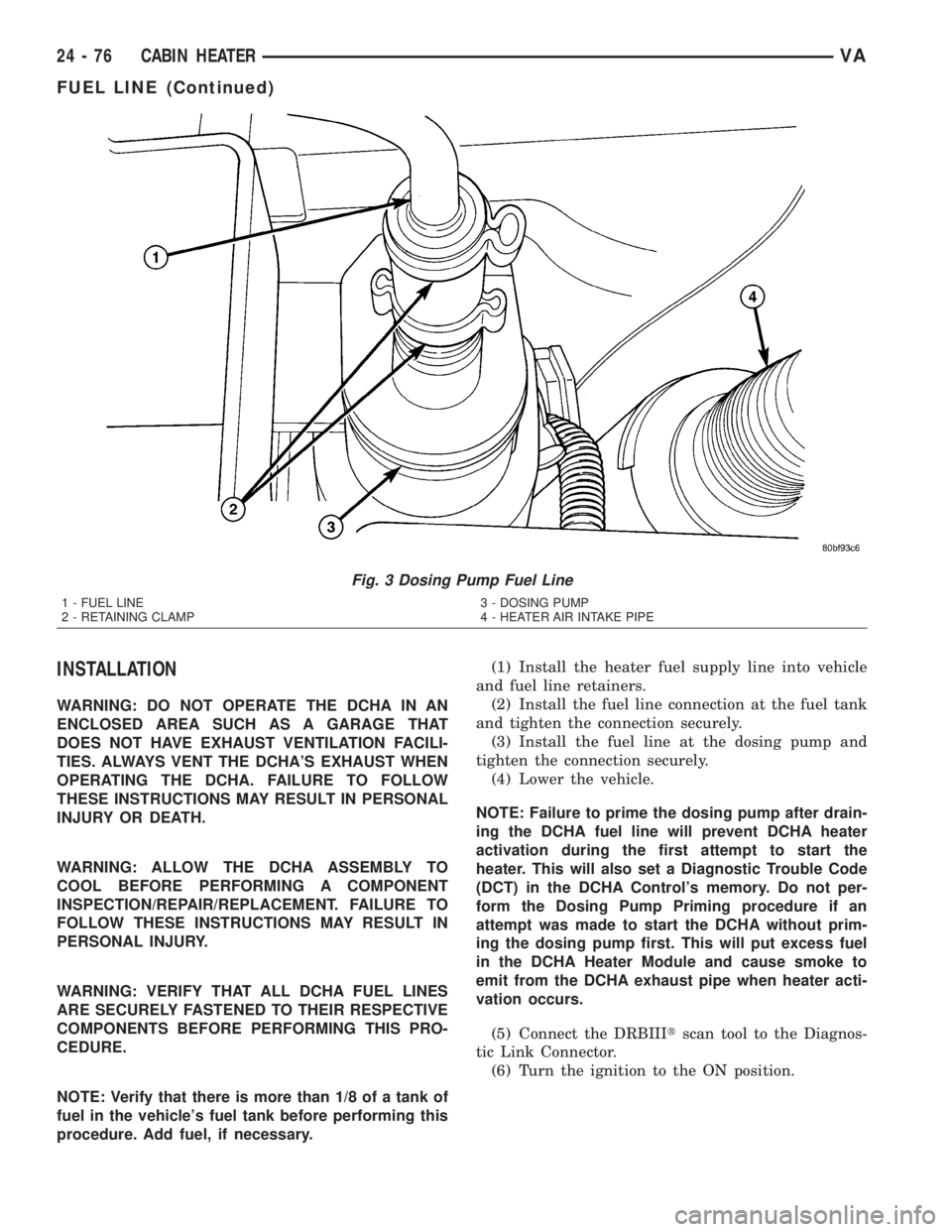
(3) Install the fuel line at the dosing pump and
tighten the connection securely.
(4) Lower the vehicle.
NOTE: Failure to prime the dosing pump after drain-
ing the DCHA fuel line will prevent DCHA heater
activation during the first attempt to start the
heater. This will also set a Diagnostic Trouble Code
(DCT) in the DCHA Control's memory. Do not per-
form the Dosing Pump Priming procedure if an
attempt was made to start the DCHA without prim-
ing the dosing pump first. This will put excess fuel
in the DCHA Heater Module and cause smoke to
emit from the DCHA exhaust pipe when heater acti-
vation occurs.
(5) Connect the DRBIIItscan tool to the Diagnos-
tic Link Connector.
(6) Turn the ignition to the ON position.
Fig. 3 Dosing Pump Fuel Line
1 - FUEL LINE
2 - RETAINING CLAMP3 - DOSING PUMP
4 - HEATER AIR INTAKE PIPE
24 - 76 CABIN HEATERVA
FUEL LINE (Continued)
Page 1205 of 1232
NOTE: Do not activate the Dosing Pump Prime
more than one time. This will put excess fuel in the
DCHA Heater Module an cause smoke to emit from
the DCHA exhaust pipe when heater activation
occurs.
NOTE: A clicking noise heard coming from the dos-
ing pump indicates that the pump is operational.
(7) With the DRBIIItscan tool in Cabin Heater,
select System Tests and Dosing Pump Prime. Allow
the dosing pump to run for the full 45 second cycle
time. When the 45 second cycle is complete, press
Page Back on the DRBIIItscan tool key pad to exit
the Dosing Pump Prime. The Dosing Pump Priming
procedure is now complete.
HEATER UNIT
REMOVAL
REMOVAL
WARNING: ALLOW THE SUPPLEMENTAL HEATER
TO COOL BEFORE PERFORMING A COMPONENT
INSPECTION/REPAIR OR REPLACEMENT. FAILURE
TO FOLLOW THESE INSTRUCTIONS MAY RESULT
IN PERSONAL INJURY.
WARNING: ALLOW THE EXHAUST SYSTEM TO
COOL BEFORE PERFORMING A COMPONENT
INSPECTION/REPAIR OR REPLACEMENT. FAILURE
TO FOLLOW THESE INSTRUCTION MAY RESULT IN
PERSONAL INJURY.
(1) Raise and support the vehicle. Take note of the
location of the flexible exhaust tube section.
(2) Drain the engine cooling system (Refer to 7 -
COOLING - STANDARD PROCEDURE).
(3) Carefully open one hose to the underbody tube
assembly and drain the remaining coolant. A salvage
hose is a good idea to control the residual coolant, as
flow will occur from both the heater and the hose and
tube assemblies.
(4) Remove the second hose from the underbody
hose and tube assembly.
(5) Loosen the hose and tube assembly from the
toe-board cross member at two locations.
(6) Disconnect the electrical connector from the
body harness near the toe-board cross member and
rail.(7) Remove the wiring harness from the toe-board
cross member (Refer to 24 - HEATING & AIR CON-
DITIONING/CABIN HEATER/HEATER UNIT -
REMOVAL).
(8) Open the fuel filler cap. Disconnect the rubber
fuel hose between the body tube assembly and the
fuel pump nipple at the body tube joint. A minimal
amount of fuel may flow from the open port.
NOTE: Utilize an approved fuel storage container to
catch any residual fuel.
(9) Loosen the two fasteners at the rail. Take care
to notice that the exhaust tube bracket tab is on top
of the heater bracket and that there are two spacer
washers installed between the rubber grommets.
(10) Remove the heater exhaust tube flex section
from the exhaust tube by loosening the bolt of the
clamp assembly. Remove the hose from the exhaust
tube. Removal of the rail tube assembly may aid in
this service operation (Refer to 24 - HEATING & AIR
CONDITIONING/CABIN HEATER/EXHAUST TUBE
- REMOVAL).
(11) Remove seat hex nut at the heater mounting
flange to cross member.
(12) Loosen the remaining fasteners which mount
the exhaust tube assembly to the vehicle.
(a) Install a suitable cabin heater support device
under the cabin heater and secure the cabin heater
to the device.
(13) Loosen the remaining three fasteners to the
cross members.
(14) Remove the loosened fasteners that support
the heater while supporting the weight of the heater.
(15) Swing the unit mounting bracket from
between the exhaust bracket and rail mounting loca-
tion. Drain any residual coolant from the heater unit.
(16) Lower the cabin heater and remove from the
supporting device and place on a suitable work area.
REMOVAL
(1) Raise and support the vehicle while taking note
of the location of the flexible exhaust tube section.
(2) Unplug the wire harness connector from vehi-
cle wiring harness to cabin heater harness.
(3) Unplug the wire harness connector from cabin
heater harness to dosing pump connector.
(4) Unplug the two wire harness connectors from
cabin heater harness to cabin heater controller con-
nectors.
(5) Remove two wiring harness connectors from
underbody.
(6) Remove two wiring harness connectors from
cabin heater shield.
(7) Carefully route the cabin heater harness to the
left side between the cabin heater unit and the cabin
heater shield.
VACABIN HEATER 24 - 77
FUEL LINE (Continued)
Page 1213 of 1232
BRAKE/PARK BRAKE INDICATOR -
OPERATION.........................8J-12
BRAKE/PARK LAMP BULB -
INSTALLATION........................8L-7
BRAKE/PARK LAMP BULB - REMOVAL.....8L-7
BRAKES, SPECIAL TOOLS................5-7
BREAKER - DESCRIPTION, CIRCUIT....8W-97-2
BREAKER - DIAGNOSIS AND TESTING,
CIRCUIT.........................8W-97-2
BREAKER - OPERATION, CIRCUIT.....8W-97-2
BREAK-IN - STANDARD PROCEDURE,
COMPRESSOR CLUTCH................24-9
BUCKLE - INSTALLATION, FRONT SEAT
BELT ..............................8O-23
BUCKLE - REMOVAL, FRONT SEAT BELT . . 8O-22
BULB - INSTALLATION, BACKUP LAMP....8L-6
BULB - INSTALLATION, BRAKE/PARK
LAMP...............................8L-7
BULB - INSTALLATION, CARGO/DOME
LAMP..............................8L-27
BULB - INSTALLATION, CENTER HIGH
MOUNTED STOP LAMP.................8L-7
BULB - INSTALLATION, CLEARANCE
LAMP...............................8L-8
BULB - INSTALLATION, DOME
LAMP/INTRUSION SENSOR.............8L-30
BULB - INSTALLATION, DOME/READING
LAMP..............................8L-29
BULB - INSTALLATION, ENTRY/EXIT
LAMP..............................8L-32
BULB - INSTALLATION, FOG LAMP.......8L-10
BULB - INSTALLATION, FRONT POSITION
LAMP..............................8L-14
BULB - INSTALLATION, FRONT
TURN/PARK/SIDE MARKER LAMP.......8L-15
BULB - INSTALLATION, HIGH BEAM
HEADLAMP.........................8L-17
BULB - INSTALLATION, LICENSE PLATE
LAMP..............................8L-18
BULB - INSTALLATION, LOW BEAM
HEADLAMP.........................8L-19
BULB - INSTALLATION, REAR SIDE
MARKER LAMP......................8L-21
BULB - INSTALLATION, REAR TURN
LAMP..............................8L-22
BULB - INSTALLATION, REPEATER LAMP . . 8L-22
BULB - REMOVAL, BACKUP LAMP........8L-5
BULB - REMOVAL, BRAKE/PARK LAMP....8L-7
BULB - REMOVAL, CARGO/DOME LAMP . . 8L-27
BULB - REMOVAL, CENTER HIGH
MOUNTED STOP LAMP.................8L-7
BULB - REMOVAL, CLEARANCE LAMP.....8L-8
BULB - REMOVAL, DOME LAMP/
INTRUSION SENSOR..................8L-30
BULB - REMOVAL, DOME/READING
LAMP..............................8L-29
BULB - REMOVAL, ENTRY/EXIT LAMP....8L-31
BULB - REMOVAL, FOG LAMP..........8L-10
BULB - REMOVAL, FRONT POSITION
LAMP..............................8L-14
BULB - REMOVAL, FRONT TURN/PARK/
SIDE MARKER LAMP.................8L-14
BULB - REMOVAL, HIGH BEAM
HEADLAMP.........................8L-17
BULB - REMOVAL, LICENSE PLATE
LAMP..............................8L-17
BULB - REMOVAL, LOW BEAM
HEADLAMP.........................8L-18
BULB - REMOVAL, REAR SIDE MARKER
LAMP..............................8L-21
BULB - REMOVAL, REAR TURN LAMP....8L-21
BULB - REMOVAL, REPEATER LAMP.....8L-22
BULKHEAD - INSTALLATION............8L-29
BULKHEAD - REMOVAL................8L-28
BULKHEAD TRIM PANEL -
INSTALLATION.......................23-69
BULKHEAD TRIM PANEL -
INSTALLATION, BACKLITE..............23-81
BULKHEAD TRIM PANEL - REMOVAL.....23-69
BULKHEAD TRIM PANEL - REMOVAL,
BACKLITE..........................23-81
BUMPER - STEP - INSTALLATION, REAR
. . . 13-3
BUMPER - STEP - REMOVAL, REAR
.......13-3
BUMPER - STEPS - INSTALLATION,
FRONT
..............................13-2
BUMPER - STEPS - REMOVAL, FRONT
.....13-2
BURNT FLUID - DIAGNOSIS AND
TESTING, CAUSES OF
................21-102BUSHINGS - INSTALLATION..............2-3
BUSHINGS - REMOVAL..................2-3
BUZZ, SQUEAK & RATTLE - STANDARD
PROCEDURE........................23-10
CABIN HEATER - DESCRIPTION.........24-72
CABIN HEATER - OPERATION...........24-72
CABLE - DESCRIPTION.................8P-3
CABLE - DIAGNOSIS AND TESTING,
GEARSHIFT........................21-109
CABLE - INSTALLATION, ANTENNA BODY . . 8A-1
CABLE - INSTALLATION, GEARSHIFT....21-109
CABLE - INSTALLATION, INSTRUMENT
PANEL ANTENNA......................8A-2
CABLE - INSTALLATION, LATCH RELEASE . 23-51
CABLE - INSTALLATION, PARK LOCK....21-126
CABLE - REMOVAL, ANTENNA BODY......8A-1
CABLE - REMOVAL, GEARSHIFT........21-109
CABLE - REMOVAL, INSTRUMENT PANEL
ANTENNA...........................8A-1
CABLE - REMOVAL, LATCH RELEASE.....23-51
CABLE - REMOVAL, PARK LOCK........21-125
CABLE TENSIONER - INSTALLATION......5-23
CABLE TENSIONER - REMOVAL..........5-23
CABLES - ADJUSTMENT, PARKING
BRAKE..............................5-25
CABLES - DESCRIPTION, BATTERY.......8F-14
CABLES - DIAGNOSIS AND TESTING,
BATTERY...........................8F-14
CABLES - INSTALLATION, BATTERY......8F-16
CABLES - INSTALLATION, MODE DOOR . . . 24-19
CABLES - OPERATION, BATTERY........8F-14
CABLES - REMOVAL, BATTERY..........8F-16
CABLES - REMOVAL, MODE DOOR.......24-19
CAMSHAFT POSITION - STANDARD
PROCEDURE, CHECKING................9-27
CAMSHAFT POSITION SENSOR -
DESCRIPTION.......................14-19
CAMSHAFT POSITION SENSOR -
INSTALLATION.......................14-19
CAMSHAFT POSITION SENSOR -
OPERATION.........................14-19
CAMSHAFT POSITION SENSOR -
REMOVAL..........................14-19
CAMSHAFT(S) - INSTALLATION..........9-29
CAMSHAFT(S) - REMOVAL..............9-28
CAP - DESCRIPTION, RADIATOR
PRESSURE..........................7-18
CAP - DIAGNOSIS AND TESTING,
RADIATOR PRESSURE.................7-19
CAP - OPERATION, RADIATOR
PRESSURE..........................7-18
CAPACITIES - SPECIFICATIONS, FLUID......0-4
CAPACITY, SPECIFICATIONS - CHARGE . . . 24-49
CARGO/DOME LAMP BULB -
INSTALLATION.......................8L-27
CARGO/DOME LAMP BULB - REMOVAL . . . 8L-27
CARGO/DOME LAMP UNIT -
INSTALLATION.......................8L-28
CARGO/DOME LAMP UNIT - REMOVAL . . . 8L-28
CARPETS AND FLOOR MATS -
INSTALLATION.......................23-70
CARPETS AND FLOOR MATS - REMOVAL . 23-69
CARRIER - INSTALLATION, SPARE TIRE . . . 22-10
CARRIER - REMOVAL, SPARE TIRE......22-10
CATALYTIC CONVERTER - INSTALLATION . . . 11-3
CATALYTIC CONVERTER - REMOVAL......11-3
CAUSES OF BURNT FLUID - DIAGNOSIS
AND TESTING
......................21-102
CAUTION - CAUTION
..................24-45
CAUTION - REFRIGERANT HOSES/LINES/
TUBES PRECAUTIONS
.................24-45
CAUTION, CAUTION
...................24-45
CAUTION, INTERIOR
..................23-67
CENTER - DESCRIPTION, POWER
DISTRIBUTION
....................8W-97-3
CENTER - OPERATION, POWER
DISTRIBUTION
....................8W-97-3
CENTER BEARING - INSTALLATION
........3-9
CENTER BEARING - REMOVAL
............3-8
CENTER BEZEL - INSTALLATION,
INSTRUMENT PANEL
..................23-55
CENTER BEZEL - REMOVAL,
INSTRUMENT PANEL
..................23-55
CENTER HIGH MOUNTED STOP LAMP
BULB - INSTALLATION
.................8L-7
CENTER HIGH MOUNTED STOP LAMP
BULB - REMOVAL
.....................8L-7CENTER HIGH MOUNTED STOP LAMP
UN - INSTALLATION...................8L-8
CENTER HIGH MOUNTED STOP LAMP
UN - REMOVAL.......................8L-8
CENTER ROLLER ARM - INSTALLATION . . . 23-38
CENTER ROLLER ARM - REMOVAL......23-37
CENTER TRACK - INSTALLATION........23-39
CENTER TRACK - REMOVAL............23-38
CENTERING - STANDARD PROCEDURE,
CLOCKSPRING......................8O-13
CENTRAL TIMER MODULE -
DESCRIPTION........................8E-1
CENTRAL TIMER MODULE - DIAGNOSIS
AND TESTING........................8E-2
CENTRAL TIMER MODULE -
INSTALLATION........................8E-2
CENTRAL TIMER MODULE - OPERATION . . . 8E-2
CENTRAL TIMER MODULE - REMOVAL....8E-2
CHAIN - INSTALLATION, OIL PUMP.......9-54
CHAIN - INSTALLATION, TIMING.........9-67
CHAIN - REMOVAL, OIL PUMP...........9-53
CHAIN - REMOVAL, TIMING.............9-63
CHAIN COVER - INSTALLATION, TIMING . . . 9-60
CHAIN COVER - REMOVAL, TIMING.......9-59
CHAIN TENSIONER - INSTALLATION,
TIMING.............................9-71
CHAIN TENSIONER - REMOVAL, TIMING . . . 9-70
CHAIN TENSIONING RAIL -
INSTALLATION, TIMING.................9-66
CHAIN TENSIONING RAIL - REMOVAL,
TIMING.............................9-63
CHARGE - STANDARD PROCEDURE,
REFRIGERANT SYSTEM...............24-48
CHARGE AIR COOLER AND PLUMBING -
CLEANING...........................11-5
CHARGE AIR COOLER AND PLUMBING -
DESCRIPTION........................11-4
CHARGE AIR COOLER AND PLUMBING -
INSPECTION.........................11-5
CHARGE AIR COOLER AND PLUMBING -
INSTALLATION........................11-5
CHARGE AIR COOLER AND PLUMBING -
OPERATION..........................11-4
CHARGE AIR COOLER AND PLUMBING -
REMOVAL...........................11-5
CHARGE AIR COOLER SYSTEM - LEAKS
- DIAGNOSIS AND TESTING.............11-4
CHARGE CAPACITY, SPECIFICATIONS.....24-49
CHARGING - STANDARD PROCEDURE,
BATTERY............................8F-8
CHARGING INDICATOR - DESCRIPTION . . . 8J-13
CHARGING INDICATOR - OPERATION.....8J-13
CHART - SPECIFICATIONS, TORQUE....5-29,5-5
CHART - SPECIFICATIONS, TORQUE.....19-10,
19-14,19-5,19-9
CHART - SPECIFICATIONS, TORQUE....2-12,2-2
CHART, SPECIFICATIONS - TORQUE.......5-22
CHART, SPECIFICATIONS - TORQUE.......22-5
CHECK - INSTALLATION..........23-13,23-24
CHECK - REMOVAL..............23-13,23-24
CHECK OIL LEVEL - STANDARD
PROCEDURE.......................21-102
CHECK VALVE - DESCRIPTION...........8R-7
CHECK VALVE - INSTALLATION..........8R-7
CHECK VALVE - OPERATION.............8R-7
CHECK VALVE - REMOVAL..............8R-7
CHECKING AND REPAIRING
CONNECTING RODS - STANDARD
PROCEDURE.........................9-40
CHECKING BATTERY ELECTROLYTE
LEVEL - STANDARD PROCEDURE........8F-12
CHECKING CAMSHAFT POSITION -
STANDARD PROCEDURE................9-27
CHECKS - DIAGNOSIS AND TESTING,
PRELIMINARY.........................7-1
CHIME WARNING SYSTEM - DIAGNOSIS
AND TESTING........................8B-2
CHIME/BUZZER - DESCRIPTION..........8B-1
CHIME/BUZZER - OPERATION............8B-1
CIGAR LIGHTER OUTLET -
DESCRIPTION.....................8W-97-1
CIGAR LIGHTER OUTLET - DIAGNOSIS
AND TESTING
.....................8W-97-2
CIGAR LIGHTER OUTLET - OPERATION
. 8W-97-2
CIGAR LIGHTER OUTLET - REMOVAL
. . 8W-97-2
CIRCUIT BREAKER - DESCRIPTION
....8W-97-2
CIRCUIT BREAKER - DIAGNOSIS AND
TESTING
.........................8W-97-2
VAINDEX 3
Description Group-Page Description Group-Page Description Group-Page