coolant temperature MERCEDES-BENZ SPRINTER 2005 Service User Guide
[x] Cancel search | Manufacturer: MERCEDES-BENZ, Model Year: 2005, Model line: SPRINTER, Model: MERCEDES-BENZ SPRINTER 2005Pages: 1232, PDF Size: 39.23 MB
Page 106 of 1232
acteristics than ethylene glycol. This can increase
cylinder head temperatures under certain conditions.
Propylene-glycol/Ethylene-glycol MixturesÐShould Not Be
Used in Chrysler Vehicles
Propylene-glycol/ethylene-glycol Mixtures can
cause the destabilization of various corrosion inhibi-
tors, causing damage to the various cooling system
components. Also, once ethylene-glycol and propy-
lene-glycol based coolants are mixed in the vehicle,
conventional methods of determining freeze point will
not be accurate. Both the refractive index and spe-
cific gravity differ between ethylene glycol and propy-
lene glycol.
CAUTION: Richer antifreeze mixtures cannot be
measured with normal field equipment and can
cause problems associated with 100 percent ethyl-
ene-glycol.
DIAGNOSIS AND TESTING - COOLING SYSTEM
LEAKS
ULTRAVIOLET LIGHT METHOD
A leak detection additive is available through the
parts department that can be added to cooling sys-
tem. The additive is highly visible under ultraviolet
light (black light). Pour one ounce of additive into
cooling system. Place heater control unit in HEAT
position. Start and operate engine until radiator
upper hose is warm to touch. Aim the commercially
available black light tool at components to be
checked. If leaks are present, black light will cause
additive to glow a bright green color.
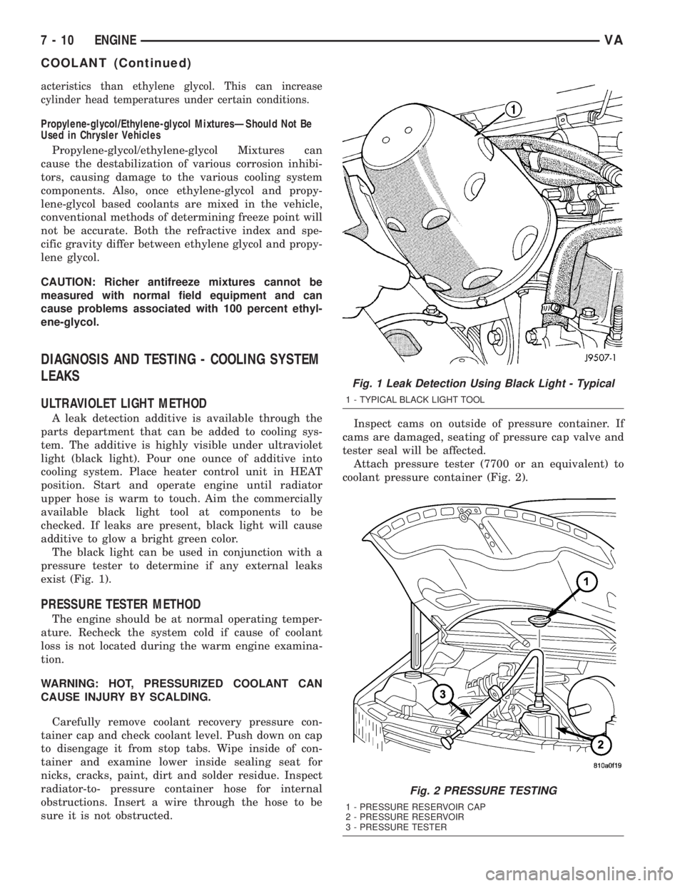
The black light can be used in conjunction with a
pressure tester to determine if any external leaks
exist (Fig. 1).
PRESSURE TESTER METHOD
The engine should be at normal operating temper-
ature. Recheck the system cold if cause of coolant
loss is not located during the warm engine examina-
tion.
WARNING: HOT, PRESSURIZED COOLANT CAN
CAUSE INJURY BY SCALDING.
Carefully remove coolant recovery pressure con-
tainer cap and check coolant level. Push down on cap
to disengage it from stop tabs. Wipe inside of con-
tainer and examine lower inside sealing seat for
nicks, cracks, paint, dirt and solder residue. Inspect
radiator-to- pressure container hose for internal
obstructions. Insert a wire through the hose to be
sure it is not obstructed.Inspect cams on outside of pressure container. If
cams are damaged, seating of pressure cap valve and
tester seal will be affected.
Attach pressure tester (7700 or an equivalent) to
coolant pressure container (Fig. 2).
Fig. 1 Leak Detection Using Black Light - Typical
1 - TYPICAL BLACK LIGHT TOOL
Fig. 2 PRESSURE TESTING
1 - PRESSURE RESERVOIR CAP
2 - PRESSURE RESERVOIR
3 - PRESSURE TESTER
7 - 10 ENGINEVA
COOLANT (Continued)
Page 108 of 1232
CAUTION: Do not use coolant additives that are
claimed to improve engine cooling.
STANDARD PROCEDURE - DRAINING COOLING
SYSTEM
WARNING: DO NOT REMOVE THE CYLINDER
BLOCK DRAIN PLUG OR LOOSEN THE RADIATOR
DRAIN PLUG WITH SYSTEM HOT AND UNDER
PRESSURE. SERIOUS BURNS FROM COOLANT
CAN OCCUR.
(1) DO NOT remove coolant recovery pressure con-
tainer cap first. With engine cold, raise vehicle on a
hoist and locate radiator draincock.
NOTE: Radiator draincock is located on the left/
lower side of radiator.
(2)
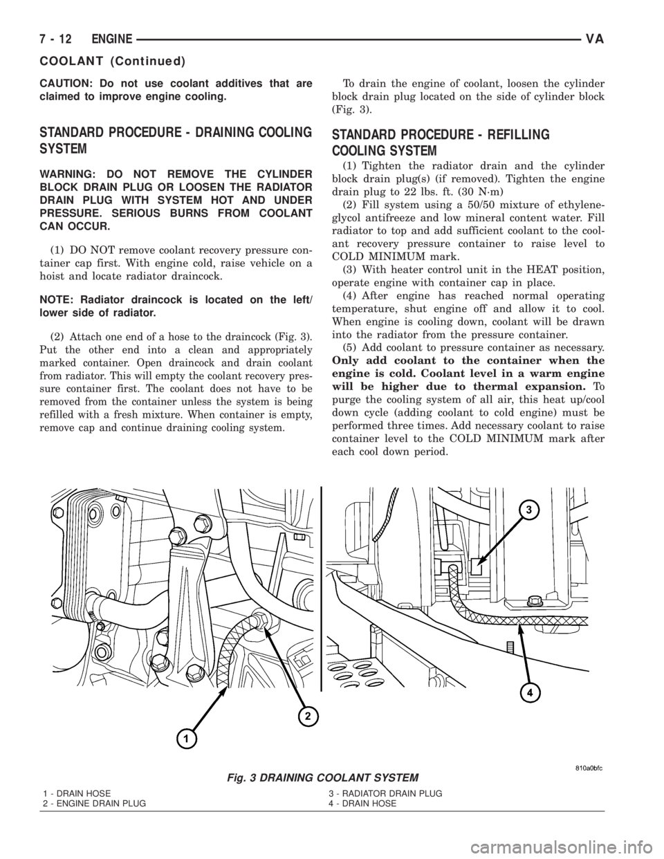
Attach one end of a hose to the draincock (Fig. 3).
Put the other end into a clean and appropriately
marked container. Open draincock and drain coolant
from radiator. This will empty the coolant recovery pres-
sure container first. The coolant does not have to be
removed from the container unless the system is being
refilled with a fresh mixture. When container is empty,
remove cap and continue draining cooling system.
To drain the engine of coolant, loosen the cylinder
block drain plug located on the side of cylinder block
(Fig. 3).
STANDARD PROCEDURE - REFILLING
COOLING SYSTEM
(1) Tighten the radiator drain and the cylinder
block drain plug(s) (if removed). Tighten the engine
drain plug to 22 lbs. ft. (30 N´m)
(2) Fill system using a 50/50 mixture of ethylene-
glycol antifreeze and low mineral content water. Fill
radiator to top and add sufficient coolant to the cool-
ant recovery pressure container to raise level to
COLD MINIMUM mark.
(3) With heater control unit in the HEAT position,
operate engine with container cap in place.
(4) After engine has reached normal operating
temperature, shut engine off and allow it to cool.
When engine is cooling down, coolant will be drawn
into the radiator from the pressure container.
(5) Add coolant to pressure container as necessary.
Only add coolant to the container when the
engine is cold. Coolant level in a warm engine
will be higher due to thermal expansion.To
purge the cooling system of all air, this heat up/cool
down cycle (adding coolant to cold engine) must be
performed three times. Add necessary coolant to raise
container level to the COLD MINIMUM mark after
each cool down period.
Fig. 3 DRAINING COOLANT SYSTEM
1 - DRAIN HOSE 3 - RADIATOR DRAIN PLUG
2 - ENGINE DRAIN PLUG 4 - DRAIN HOSE
7 - 12 ENGINEVA
COOLANT (Continued)
Page 110 of 1232
(6) Properly align the radiator assembly and
install the front end cross member.
(7) Connect negative battery cable.
ENGINE BLOCK HEATER
REMOVAL
WARNING: RISK OF INJURY TO SKIN AND EYES
DUE TO SCALDING FROM HOT COOLANT. DO NOT
OPEN THE COOLING SYSTEM UNLESS THE TEM-
PERATURE IS BELOW 194ÉF (90ÉC). WEAR PRO-
TECTIVE CLOTHING AND EYE WEAR. RISK OF
POISONING IF COOLANT IS SWALLOWED. STORE
COOLANT IN PROPER AND APPROPRIATELY
MARKED CONTAINERS.
(1) Disconnect the negative battery cable.
(2) Drain the cooling system.
(3) Record the location and snip the wire ties.
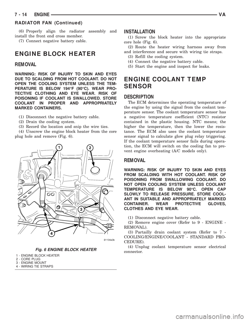
(4) Unscrew the engine block heater from the core
plug hole and remove (Fig. 6).
INSTALLATION
(1) Screw the block heater into the appropriate
core hole (Fig. 6).
(2) Route the heater wiring harness away from
and interference and secure with wiring tie straps.
(3) Refill the cooling system.
(4) Connect the negative battery cable.
(5) Start the engine and inspect for leaks.
ENGINE COOLANT TEMP
SENSOR
DESCRIPTION
The ECM determines the operating temperature of
the engine by using the signal from the coolant tem-
perature sensor. The coolant temperature sensor has
a negative temperature coefficient (NTC) resistor
contained in the plastic housing. NTC means; the
higher the temperature, then the lower the resis-
tance. The ECM also uses the coolant temperature
sensor signal to calculate glow plug relay triggering.
If the coolant temperature sensor fails during opera-
tion, the ECM will switch on the cooling fan to pre-
vent engine overheating (A/C models only).
REMOVAL
WARNING: RISK OF INJURY TO SKIN AND EYES
FROM SCALDING WITH HOT COOLANT. RISK OF
POISONING FROM SWALLOWING COOLANT. DO
NOT OPEN COOLING SYSTEM UNLESS COOLANT
TEMPERATURE IS BELOW 90ÉC. OPEN CAP
SLOWLY TO RELEASE PRESSURE. STORE COOL-
ANT IN SUITABLE AND APPROPRIATELY MARKED
CONTAINER. WEAR PROTECTIVE GLOVES,
CLOTHES AND EYE WEAR.
(1) Disconnect negative battery cable.
(2) Remove engine cover (Refer to 9 - ENGINE -
REMOVAL).
(3) Partailly drain coolant system (Refer to 7 -
COOLING/ENGINE/COOLANT - STANDARD PRO-
CEDURE).
(4) Unplug coolant temperature sensor electrical
connector.
Fig. 6 ENGINE BLOCK HEATER
1 - ENGINE BLOCK HEATER
2 - CORE PLUG
3 - ENGINE MOUNT
4 - WIRING TIE STRAPS
7 - 14 ENGINEVA
RADIATOR FAN (Continued)
Page 111 of 1232
NOTE: Capture any residual coolant that may flow.
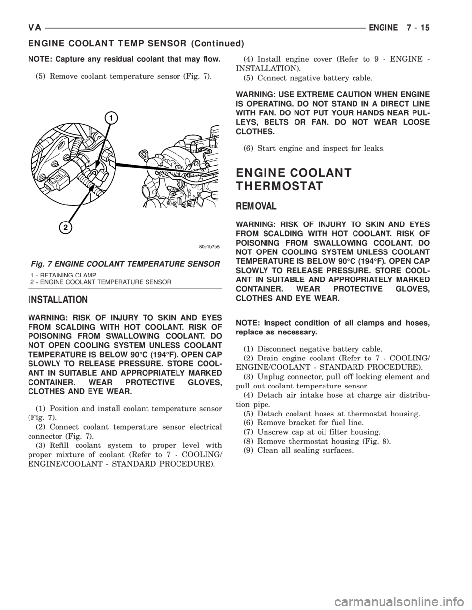
(5) Remove coolant temperature sensor (Fig. 7).
INSTALLATION
WARNING: RISK OF INJURY TO SKIN AND EYES
FROM SCALDING WITH HOT COOLANT. RISK OF
POISONING FROM SWALLOWING COOLANT. DO
NOT OPEN COOLING SYSTEM UNLESS COOLANT
TEMPERATURE IS BELOW 90ÉC (194ÉF). OPEN CAP
SLOWLY TO RELEASE PRESSURE. STORE COOL-
ANT IN SUITABLE AND APPROPRIATELY MARKED
CONTAINER. WEAR PROTECTIVE GLOVES,
CLOTHES AND EYE WEAR.
(1) Position and install coolant temperature sensor
(Fig. 7).
(2) Connect coolant temperature sensor electrical
connector (Fig. 7).
(3) Refill coolant system to proper level with
proper mixture of coolant (Refer to 7 - COOLING/
ENGINE/COOLANT - STANDARD PROCEDURE).(4) Install engine cover (Refer to 9 - ENGINE -
INSTALLATION).
(5) Connect negative battery cable.
WARNING: USE EXTREME CAUTION WHEN ENGINE
IS OPERATING. DO NOT STAND IN A DIRECT LINE
WITH FAN. DO NOT PUT YOUR HANDS NEAR PUL-
LEYS, BELTS OR FAN. DO NOT WEAR LOOSE
CLOTHES.
(6) Start engine and inspect for leaks.
ENGINE COOLANT
THERMOSTAT
REMOVAL
WARNING: RISK OF INJURY TO SKIN AND EYES
FROM SCALDING WITH HOT COOLANT. RISK OF
POISONING FROM SWALLOWING COOLANT. DO
NOT OPEN COOLING SYSTEM UNLESS COOLANT
TEMPERATURE IS BELOW 90ÉC (194ÉF). OPEN CAP
SLOWLY TO RELEASE PRESSURE. STORE COOL-
ANT IN SUITABLE AND APPROPRIATELY MARKED
CONTAINER. WEAR PROTECTIVE GLOVES,
CLOTHES AND EYE WEAR.
NOTE: Inspect condition of all clamps and hoses,
replace as necessary.
(1) Disconnect negative battery cable.
(2) Drain engine coolant (Refer to 7 - COOLING/
ENGINE/COOLANT - STANDARD PROCEDURE).
(3) Unplug connector, pull off locking element and
pull out coolant temperature sensor.
(4) Detach air intake hose at charge air distribu-
tion pipe.
(5) Detach coolant hoses at thermostat housing.
(6) Remove bracket for fuel line.
(7) Unscrew cap at oil filter housing.
(8) Remove thermostat housing (Fig. 8).
(9) Clean all sealing surfaces.
Fig. 7 ENGINE COOLANT TEMPERATURE SENSOR
1 - RETAINING CLAMP
2 - ENGINE COOLANT TEMPERATURE SENSOR
VAENGINE 7 - 15
ENGINE COOLANT TEMP SENSOR (Continued)
Page 112 of 1232
INSTALLATION
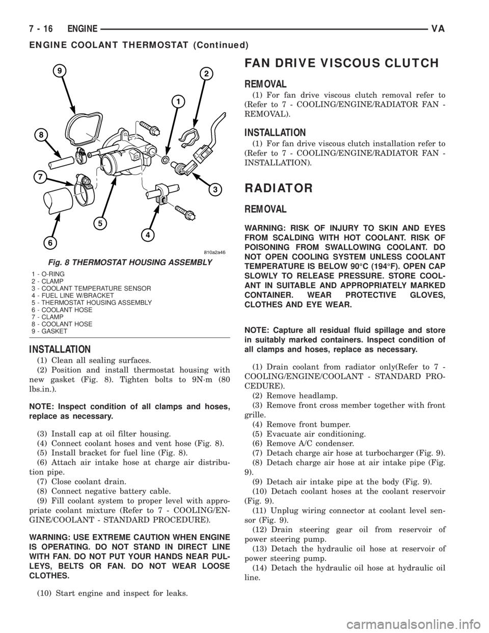
(1) Clean all sealing surfaces.
(2) Position and install thermostat housing with
new gasket (Fig. 8). Tighten bolts to 9N´m (80
lbs.in.).
NOTE: Inspect condition of all clamps and hoses,
replace as necessary.
(3) Install cap at oil filter housing.
(4) Connect coolant hoses and vent hose (Fig. 8).
(5) Install bracket for fuel line (Fig. 8).
(6) Attach air intake hose at charge air distribu-
tion pipe.
(7) Close coolant drain.
(8) Connect negative battery cable.
(9) Fill coolant system to proper level with appro-
priate coolant mixture (Refer to 7 - COOLING/EN-
GINE/COOLANT - STANDARD PROCEDURE).
WARNING: USE EXTREME CAUTION WHEN ENGINE
IS OPERATING. DO NOT STAND IN DIRECT LINE
WITH FAN. DO NOT PUT YOUR HANDS NEAR PUL-
LEYS, BELTS OR FAN. DO NOT WEAR LOOSE
CLOTHES.
(10) Start engine and inspect for leaks.
FAN DRIVE VISCOUS CLUTCH
REMOVAL
(1) For fan drive viscous clutch removal refer to
(Refer to 7 - COOLING/ENGINE/RADIATOR FAN -
REMOVAL).
INSTALLATION
(1) For fan drive viscous clutch installation refer to
(Refer to 7 - COOLING/ENGINE/RADIATOR FAN -
INSTALLATION).
RADIATOR
REMOVAL
WARNING: RISK OF INJURY TO SKIN AND EYES
FROM SCALDING WITH HOT COOLANT. RISK OF
POISONING FROM SWALLOWING COOLANT. DO
NOT OPEN COOLING SYSTEM UNLESS COOLANT
TEMPERATURE IS BELOW 90ÉC (194ÉF). OPEN CAP
SLOWLY TO RELEASE PRESSURE. STORE COOL-
ANT IN SUITABLE AND APPROPRIATELY MARKED
CONTAINER. WEAR PROTECTIVE GLOVES,
CLOTHES AND EYE WEAR.
NOTE: Capture all residual fluid spillage and store
in suitably marked containers. Inspect condition of
all clamps and hoses, replace as necessary.
(1) Drain coolant from radiator only(Refer to 7 -
COOLING/ENGINE/COOLANT - STANDARD PRO-
CEDURE).
(2) Remove headlamp.
(3) Remove front cross member together with front
grille.
(4) Remove front bumper.
(5) Evacuate air conditioning.
(6) Remove A/C condenser.
(7) Detach charge air hose at turbocharger (Fig. 9).
(8) Detach charge air hose at air intake pipe (Fig.
9).
(9) Detach air intake pipe at the body (Fig. 9).
(10) Detach coolant hoses at the coolant reservoir
(Fig. 9).
(11) Unplug wiring connector at coolant level sen-
sor (Fig. 9).
(12) Drain steering gear oil from reservoir of
power steering pump.
(13) Detach the hydraulic oil hose at reservoir of
power steering pump.
(14) Detach the hydraulic oil hose at hydraulic oil
line.
Fig. 8 THERMOSTAT HOUSING ASSEMBLY
1 - O-RING
2 - CLAMP
3 - COOLANT TEMPERATURE SENSOR
4 - FUEL LINE W/BRACKET
5 - THERMOSTAT HOUSING ASSEMBLY
6 - COOLANT HOSE
7 - CLAMP
8 - COOLANT HOSE
9 - GASKET
7 - 16 ENGINEVA
ENGINE COOLANT THERMOSTAT (Continued)
Page 115 of 1232
DIAGNOSIS AND TESTING - RADIATOR
PRESSURE CAP
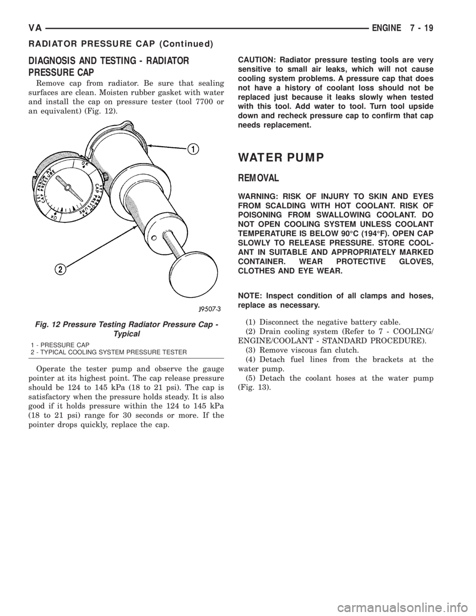
Remove cap from radiator. Be sure that sealing
surfaces are clean. Moisten rubber gasket with water
and install the cap on pressure tester (tool 7700 or
an equivalent) (Fig. 12).
Operate the tester pump and observe the gauge
pointer at its highest point. The cap release pressure
should be 124 to 145 kPa (18 to 21 psi). The cap is
satisfactory when the pressure holds steady. It is also
good if it holds pressure within the 124 to 145 kPa
(18 to 21 psi) range for 30 seconds or more. If the
pointer drops quickly, replace the cap.CAUTION: Radiator pressure testing tools are very
sensitive to small air leaks, which will not cause
cooling system problems. A pressure cap that does
not have a history of coolant loss should not be
replaced just because it leaks slowly when tested
with this tool. Add water to tool. Turn tool upside
down and recheck pressure cap to confirm that cap
needs replacement.
WATER PUMP
REMOVAL
WARNING: RISK OF INJURY TO SKIN AND EYES
FROM SCALDING WITH HOT COOLANT. RISK OF
POISONING FROM SWALLOWING COOLANT. DO
NOT OPEN COOLING SYSTEM UNLESS COOLANT
TEMPERATURE IS BELOW 90ÉC (194ÉF). OPEN CAP
SLOWLY TO RELEASE PRESSURE. STORE COOL-
ANT IN SUITABLE AND APPROPRIATELY MARKED
CONTAINER. WEAR PROTECTIVE GLOVES,
CLOTHES AND EYE WEAR.
NOTE: Inspect condition of all clamps and hoses,
replace as necessary.
(1) Disconnect the negative battery cable.
(2) Drain cooling system (Refer to 7 - COOLING/
ENGINE/COOLANT - STANDARD PROCEDURE).
(3) Remove viscous fan clutch.
(4) Detach fuel lines from the brackets at the
water pump.
(5) Detach the coolant hoses at the water pump
(Fig. 13).
Fig. 12 Pressure Testing Radiator Pressure Cap -
Typical
1 - PRESSURE CAP
2 - TYPICAL COOLING SYSTEM PRESSURE TESTER
VAENGINE 7 - 19
RADIATOR PRESSURE CAP (Continued)
Page 124 of 1232
REMOVAL
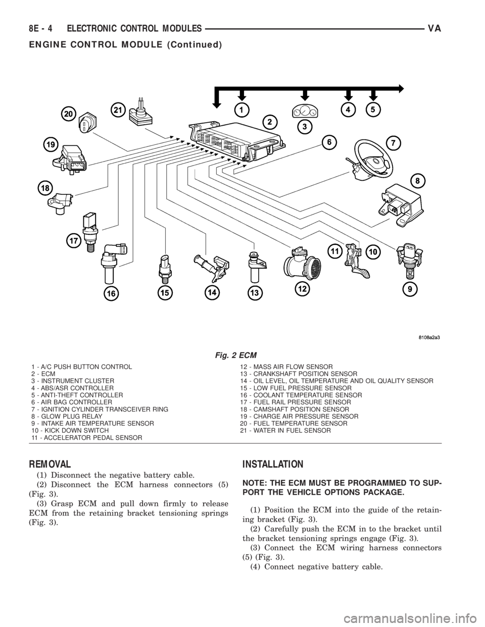
(1) Disconnect the negative battery cable.
(2) Disconnect the ECM harness connectors (5)
(Fig. 3).
(3) Grasp ECM and pull down firmly to release
ECM from the retaining bracket tensioning springs
(Fig. 3).
INSTALLATION
NOTE: THE ECM MUST BE PROGRAMMED TO SUP-
PORT THE VEHICLE OPTIONS PACKAGE.
(1) Position the ECM into the guide of the retain-
ing bracket (Fig. 3).
(2) Carefully push the ECM in to the bracket until
the bracket tensioning springs engage (Fig. 3).
(3) Connect the ECM wiring harness connectors
(5) (Fig. 3).
(4) Connect negative battery cable.
Fig. 2 ECM
1 - A/C PUSH BUTTON CONTROL 12 - MASS AIR FLOW SENSOR
2 - ECM 13 - CRANKSHAFT POSITION SENSOR
3 - INSTRUMENT CLUSTER 14 - OIL LEVEL, OIL TEMPERATURE AND OIL QUALITY SENSOR
4 - ABS/ASR CONTROLLER 15 - LOW FUEL PRESSURE SENSOR
5 - ANTI-THEFT CONTROLLER 16 - COOLANT TEMPERATURE SENSOR
6 - AIR BAG CONTROLLER 17 - FUEL RAIL PRESSURE SENSOR
7 - IGNITION CYLINDER TRANSCEIVER RING 18 - CAMSHAFT POSITION SENSOR
8 - GLOW PLUG RELAY 19 - CHARGE AIR PRESSURE SENSOR
9 - INTAKE AIR TEMPERATURE SENSOR 20 - FUEL TEMPERATURE SENSOR
10 - KICK DOWN SWITCH 21 - WATER IN FUEL SENSOR
11 - ACCELERATOR PEDAL SENSOR
8E - 4 ELECTRONIC CONTROL MODULESVA
ENGINE CONTROL MODULE (Continued)
Page 126 of 1232
The TCM continuously checks for electrical prob-
lems, mechanical problems, and some hydraulic prob-
lems. When a problem is sensed, the TCM stores a
diagnostic trouble code (DTC). Some of these codes
cause the transmission to go into9Limp-In9or
9default9mode. Some DTCs cause permanent
Limp-In and others cause temporary Limp-In. The
NAG1 defaults in the current gear position if a DTC
is detected, then after a key cycle the transmission
will go into Limp-in, which is mechanical 2nd gear.
Some DTCs may allow the transmission to resume
normal operation (recover) if the detected problem
goes away. A permanent Limp-In DTC will recover
when the key is cycled, but if the same DTC is
detected for three key cycles the system will not
recover and the DTC must be cleared from the TCM
with the DRBIIItscan tool.
TCM SIGNALS
The TCM registers one part of the input signals by
direct inputs, the other part by CAN C bus. In addi-
tion to the direct control of the actuators, the TCM
sends various output signals by CAN C bus to other
control modules.
Selector Lever Position
The TCM monitors the SLA for all shift lever posi-
tions via the CAN bus.
ATF Temperature Sensor
The ATF temperature sensor is a positive temper-
ature co-efficient (PTC) thermistor. It measures the
temperature of the transmission fluid and is a direct
input signal for the TCM. The temperature of the
ATF has an influence on the shifttime and resulting
shift quality. As the temperature rises, resistance
rises, and therefore, the probing voltage is decreas-
ing. Because of its registration, the shifting process
can be optimized in all temperature ranges.
The ATF temperature sensor is wired in series
with the park/neutral contact. The temperature sig-
nal is transmitted to the TCM only when the reed
contact of the park/neutral contact is closed because
the TCM only reads ATF temperature while in any
forward gear, or REVERSE. When the transmission
is in PARK or NEUTRAL, the TCM will substitute
the engine temperature for the ATF temperature.
Starter Interlock
The TCM monitors a contact switch wired in series
with the transmission temperature sensor to deter-
mine PARK and NEUTRAL positions. The contact
switch is open in PARK and NEUTRAL. The TCM
senses transmission temperature as high (switch
supply voltage), confirming switch status as open.
The TCM then broadcasts a message over CAN bus
to confirm switch status. The PCM receives thisinformation and allows operation of the starter cir-
cuit.
N2 and N3 Speed Sensors
The N2 and N3 Input Speed Sensors are two Hall-
effect speed sensors that are mounted internally in
the transmission and are used by the TCM to calcu-
late the transmission's input speed. Since the input
speed cannot be measured directly, two of the drive
elements are measured. Two input speed sensors
were required because both drive elements are not
active in all gears.
CAN C Bus Indirect Input Signals
A 2.5-volt bias (operating voltage) is present on the
CAN C bus any time the ignition switch is in the
RUN position. Both the TCM and the ABS apply this
bias. On this vehicle, the CAN C bus is used for mod-
ule data exchange only. The indirect inputs used on
the NAG1 electronic control system are:
²Wheel Speed Sensors.
²Brake Switch.
²Engine RPM.
²Engine Temperature.
²Cruise Control Status.
²Gear Limit Request.
²Throttle Position - 0% at idle, 100% at WOT. If
open, TCM assumes idle (0% throttle opening).
²Odometer Mileage
²Maximum Effective Torque.
²Engine in Limp-In Mode/Mileage Where DTC
Was Set.
BRAKE TRANSMISSION SHIFT INTERLOCK (BTSI)
The BTSI solenoid prevents shifting out of the
PARK position until the ignition key is in the RUN
position and the brake pedal is pressed. The TCM
controls the ground while the ignition switch supplies
power to the BTSI solenoid. The PCM monitors the
brake switch and broadcasts brake switch status
messages over the CAN C bus. If the park brake is
depressed and there is power (Run/Start) to SLA, the
BTSI solenoid deactivates.
SHIFT SCHEDULES
The basic shift schedule includes up and down-
shifts for all five gears. The TCM adapts the shift
program according to driving style, accelerator pedal
position and deviation of vehicle speed. Influencing
factors are:
²Road Conditions.
²Incline, Decline and Altitude.
²Trailer Operation, Loading.
²Engine Coolant Temperature.
²Cruise Control Operation.
²Sporty Driving Style.
8E - 6 ELECTRONIC CONTROL MODULESVA
TRANSMISSION CONTROL MODULE (Continued)
Page 162 of 1232
OPERATION
The heated seat system is designed to provide indi-
vidually controlled, supplemental heat to the seat
cushion and seat back surfaces of both front seats.
Because this system converts electrical current to
heat, the heated seat system can provide a measure
of warm comfort almost immediately upon entering a
cold vehicle, rather than having to wait for the
engine coolant to reach sufficient temperature to
deliver heat through the conventional heater system.
This system allows each front seat occupant to indi-
vidually select one of two comfort levels, Hi or Lo, or
to turn the heater for their seat off.
The heated seat system components operate on
battery current received through a fuse in the Fuse
Block on a fused ignition switch output (run-acc) cir-
cuit so that the system will only operate when theignition switch is in the On or Accessory positions.
The heated seat system will be turned Off automati-
cally whenever the ignition switch is turned to any
position except On or Accessory. Also, the heated seat
system will not operate when the surface tempera-
ture of the seat cushion cover at either heated seat
sensor is above the designed temperature set points
of the system.
DIAGNOSIS AND TESTING - HEATED SEATS
Refer toWiringfor the appropriate wiring infor-
mation. The wiring information includes wiring dia-
grams, proper wire and connector repair procedures,
further details on wire harness routing and reten-
tion, as well as pin-out and location views for the
various wire harness connectors, splices and grounds.
HEATED SEAT SYSTEM DIAGNOSIS
CONDITION POSSIBLE CAUSES CORRECTION
NO HEATED SEAT SWITCH
ILLUMINATION WITH
IGNITION ON1. Faulty fuse. 1. Check heated seat fuse in Fuse Block.
Replace fuse, if required.
2. Wiring faulty. 2. Check fused ignition switch output (run-acc)
circuit from heated seat switch connector to
ignition switch. Repair, if required.
3. Ground faulty. 3. Check for ground at heated seat switch
connector. Repair, if required.
4. Faulty switch. 4. Refer to Heated Seat Switch for the proper
switch diagnosis and testing procedures.
DRIVER HEATED SEAT
SWITCH
DESCRIPTION
The heated seat switches are located on the instru-
ment panel, in the accessory switch bezel. The two,
momentary rocker type switches provide a signal to
the Heated Seat Relay through separate hard wired
circuits. Each switch contains two light emitting
diodes (LED), one for each High and Low setting to
let the occupant know that the seat heater system is
on.
The heated seat switches and their LED's cannot
be repaired. If either switch is faulty or damaged the
entire switch must be replaced.
OPERATION
There are three modes that can be selected with
each of the heated seat switches: Off, Low, and High.
When the top of the switch rocker is depressed, the
low mode is selected and the low mode LED indicator
illuminates. Depressing the top of the switch rocker asecond time will turn the heated seat to Off. This
same process is repeated for High heat setting. The
heated seats will automatically return to the Off
mode anytime the vehicle ignition switch is turned
Off.
Both switches provide separate hard wire inputs to
the Heated Seat Relay to indicate the selected mode.
The Heated Seat Relay responds to the heated seat
switch messages by controlling the output to the seat
heater elements of the selected seat.
DIAGNOSIS AND TESTING - DRIVER HEATED
SEAT SWITCH
For circuit description and diagrams, refer toWir-
ing.
(1) Inspect the Heated Seat Switches for apparent
damage or sticking/binding and replace if required.
Refer to Heated Seat Switch Removal and Installa-
tion in this section.
(2) Replace the heated seat switch with a known
good unit and retest the heated seat system.
8G - 2 HEATED SYSTEMSVA
HEATED SEATS (Continued)
Page 170 of 1232
GLOW PLUG RELAY
DESCRIPTION
The glow plug relay supplies battery voltage to the
glow plug through a timed cycle that is related to
coolant temperature. The glow plug relay is located
under the battery. The purpose of a glow plug system
is to improve combustion for low emissions and to
achieve easy starting at low temperatures.
OPERATION
When the ignition key is turned to the ON position,
the glow plug output stage and pre-glow indicator
lamp are actuated by the ECM. The duration of the
signal depends on the coolant temperature. The glow
plug relay has processing that communicates with the
ECM. If no data exchange occurs at the triggering
stage, the preheating is switched off after 2 seconds.
Start glowing is initiated when the key is in the
start position. The glow plugs (R13±R17) continue to
be supplied with voltage. This makes it possible to
stabilize the cold starting speed. (After glowing is ini-
tiated when the starter reject speed is reached).
After the engine starts, the ECM determines the
afterglow period in line with coolant temperature. If
no signal is received from the coolant temperature
sensor, afterglow is maintained for thirty seconds.
The following aims are reached by the afterglow :²Improvement in warming-up properties
²
Prevention of white exhaust smoke after cold start
²Stabilizing of the cold starting speed
The glow plug output stage constantly signals the
current operating state and faults. The following are
faults detected and transmitted to the ECM :
²Open circuit at one or several glow plugs
²Short circuit in the glow plug circuit
²Relay fault
If the Glow plug relay detects an open circuit at a
glow plug, it is stored and indicated only once the
engine is running by the preglow indicator lamp com-
ing on for about one minute and a fault is stored in
the ECM. If a short circuit, a glow plug output stage
faulty or a temperature related switching off of out-
put stages is detected, the fault is stored and indi-
cated immediately by the preglow indicator lamp
coming on. Once the fault is no longer current, the
indicator is immediately switched off, but the fault is
stored in the ECM. If the fault is constantly current,
the preglow indicator lamp remains on until the igni-
tion is switched off.
DIAGNOSIS AND TESTING - GLOW PLUG
RELAYS
Refer to the appropriate Diesel Powertrain Diagno-
sis Manual for information on diagnosing the glow
plug relays.
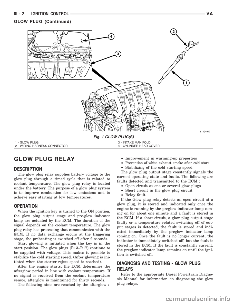
Fig. 1 GLOW PLUG(S)
1 - GLOW PLUG
2 - WIRING HARNESS CONNECTOR3 - INTAKE MANIFOLD
4 - CYLINDER HEAD COVER
8I - 2 IGNITION CONTROLVA
GLOW PLUG (Continued)