cruise control MERCEDES-BENZ SPRINTER 2005 Service Repair Manual
[x] Cancel search | Manufacturer: MERCEDES-BENZ, Model Year: 2005, Model line: SPRINTER, Model: MERCEDES-BENZ SPRINTER 2005Pages: 1232, PDF Size: 39.23 MB
Page 123 of 1232
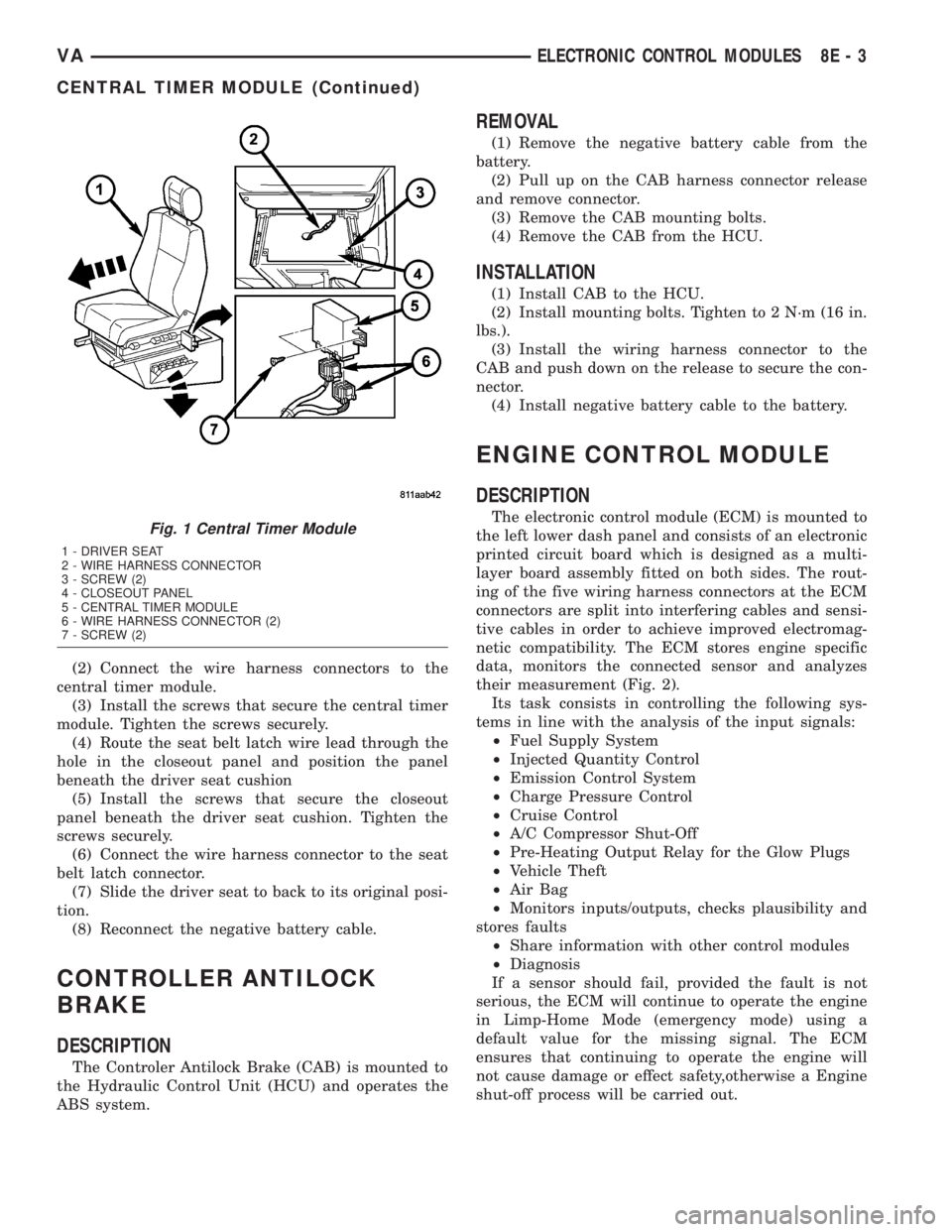
(2) Connect the wire harness connectors to the
central timer module.
(3) Install the screws that secure the central timer
module. Tighten the screws securely.
(4) Route the seat belt latch wire lead through the
hole in the closeout panel and position the panel
beneath the driver seat cushion
(5) Install the screws that secure the closeout
panel beneath the driver seat cushion. Tighten the
screws securely.
(6) Connect the wire harness connector to the seat
belt latch connector.
(7) Slide the driver seat to back to its original posi-
tion.
(8) Reconnect the negative battery cable.
CONTROLLER ANTILOCK
BRAKE
DESCRIPTION
The Controler Antilock Brake (CAB) is mounted to
the Hydraulic Control Unit (HCU) and operates the
ABS system.
REMOVAL
(1) Remove the negative battery cable from the
battery.
(2) Pull up on the CAB harness connector release
and remove connector.
(3) Remove the CAB mounting bolts.
(4) Remove the CAB from the HCU.
INSTALLATION
(1) Install CAB to the HCU.
(2) Install mounting bolts. Tighten to 2 N´m (16 in.
lbs.).
(3) Install the wiring harness connector to the
CAB and push down on the release to secure the con-
nector.
(4) Install negative battery cable to the battery.
ENGINE CONTROL MODULE
DESCRIPTION
The electronic control module (ECM) is mounted to
the left lower dash panel and consists of an electronic
printed circuit board which is designed as a multi-
layer board assembly fitted on both sides. The rout-
ing of the five wiring harness connectors at the ECM
connectors are split into interfering cables and sensi-
tive cables in order to achieve improved electromag-
netic compatibility. The ECM stores engine specific
data, monitors the connected sensor and analyzes
their measurement (Fig. 2).
Its task consists in controlling the following sys-
tems in line with the analysis of the input signals:
²Fuel Supply System
²Injected Quantity Control
²Emission Control System
²Charge Pressure Control
²Cruise Control
²A/C Compressor Shut-Off
²Pre-Heating Output Relay for the Glow Plugs
²Vehicle Theft
²Air Bag
²Monitors inputs/outputs, checks plausibility and
stores faults
²Share information with other control modules
²Diagnosis
If a sensor should fail, provided the fault is not
serious, the ECM will continue to operate the engine
in Limp-Home Mode (emergency mode) using a
default value for the missing signal. The ECM
ensures that continuing to operate the engine will
not cause damage or effect safety,otherwise a Engine
shut-off process will be carried out.Fig. 1 Central Timer Module
1 - DRIVER SEAT
2 - WIRE HARNESS CONNECTOR
3 - SCREW (2)
4 - CLOSEOUT PANEL
5 - CENTRAL TIMER MODULE
6 - WIRE HARNESS CONNECTOR (2)
7 - SCREW (2)
VAELECTRONIC CONTROL MODULES 8E - 3
CENTRAL TIMER MODULE (Continued)
Page 126 of 1232
The TCM continuously checks for electrical prob-
lems, mechanical problems, and some hydraulic prob-
lems. When a problem is sensed, the TCM stores a
diagnostic trouble code (DTC). Some of these codes
cause the transmission to go into9Limp-In9or
9default9mode. Some DTCs cause permanent
Limp-In and others cause temporary Limp-In. The
NAG1 defaults in the current gear position if a DTC
is detected, then after a key cycle the transmission
will go into Limp-in, which is mechanical 2nd gear.
Some DTCs may allow the transmission to resume
normal operation (recover) if the detected problem
goes away. A permanent Limp-In DTC will recover
when the key is cycled, but if the same DTC is
detected for three key cycles the system will not
recover and the DTC must be cleared from the TCM
with the DRBIIItscan tool.
TCM SIGNALS
The TCM registers one part of the input signals by
direct inputs, the other part by CAN C bus. In addi-
tion to the direct control of the actuators, the TCM
sends various output signals by CAN C bus to other
control modules.
Selector Lever Position
The TCM monitors the SLA for all shift lever posi-
tions via the CAN bus.
ATF Temperature Sensor
The ATF temperature sensor is a positive temper-
ature co-efficient (PTC) thermistor. It measures the
temperature of the transmission fluid and is a direct
input signal for the TCM. The temperature of the
ATF has an influence on the shifttime and resulting
shift quality. As the temperature rises, resistance
rises, and therefore, the probing voltage is decreas-
ing. Because of its registration, the shifting process
can be optimized in all temperature ranges.
The ATF temperature sensor is wired in series
with the park/neutral contact. The temperature sig-
nal is transmitted to the TCM only when the reed
contact of the park/neutral contact is closed because
the TCM only reads ATF temperature while in any
forward gear, or REVERSE. When the transmission
is in PARK or NEUTRAL, the TCM will substitute
the engine temperature for the ATF temperature.
Starter Interlock
The TCM monitors a contact switch wired in series
with the transmission temperature sensor to deter-
mine PARK and NEUTRAL positions. The contact
switch is open in PARK and NEUTRAL. The TCM
senses transmission temperature as high (switch
supply voltage), confirming switch status as open.
The TCM then broadcasts a message over CAN bus
to confirm switch status. The PCM receives thisinformation and allows operation of the starter cir-
cuit.
N2 and N3 Speed Sensors
The N2 and N3 Input Speed Sensors are two Hall-
effect speed sensors that are mounted internally in
the transmission and are used by the TCM to calcu-
late the transmission's input speed. Since the input
speed cannot be measured directly, two of the drive
elements are measured. Two input speed sensors
were required because both drive elements are not
active in all gears.
CAN C Bus Indirect Input Signals
A 2.5-volt bias (operating voltage) is present on the
CAN C bus any time the ignition switch is in the
RUN position. Both the TCM and the ABS apply this
bias. On this vehicle, the CAN C bus is used for mod-
ule data exchange only. The indirect inputs used on
the NAG1 electronic control system are:
²Wheel Speed Sensors.
²Brake Switch.
²Engine RPM.
²Engine Temperature.
²Cruise Control Status.
²Gear Limit Request.
²Throttle Position - 0% at idle, 100% at WOT. If
open, TCM assumes idle (0% throttle opening).
²Odometer Mileage
²Maximum Effective Torque.
²Engine in Limp-In Mode/Mileage Where DTC
Was Set.
BRAKE TRANSMISSION SHIFT INTERLOCK (BTSI)
The BTSI solenoid prevents shifting out of the
PARK position until the ignition key is in the RUN
position and the brake pedal is pressed. The TCM
controls the ground while the ignition switch supplies
power to the BTSI solenoid. The PCM monitors the
brake switch and broadcasts brake switch status
messages over the CAN C bus. If the park brake is
depressed and there is power (Run/Start) to SLA, the
BTSI solenoid deactivates.
SHIFT SCHEDULES
The basic shift schedule includes up and down-
shifts for all five gears. The TCM adapts the shift
program according to driving style, accelerator pedal
position and deviation of vehicle speed. Influencing
factors are:
²Road Conditions.
²Incline, Decline and Altitude.
²Trailer Operation, Loading.
²Engine Coolant Temperature.
²Cruise Control Operation.
²Sporty Driving Style.
8E - 6 ELECTRONIC CONTROL MODULESVA
TRANSMISSION CONTROL MODULE (Continued)