instrument panel MERCEDES-BENZ SPRINTER 2005 Service Repair Manual
[x] Cancel search | Manufacturer: MERCEDES-BENZ, Model Year: 2005, Model line: SPRINTER, Model: MERCEDES-BENZ SPRINTER 2005Pages: 1232, PDF Size: 39.23 MB
Page 4 of 1232
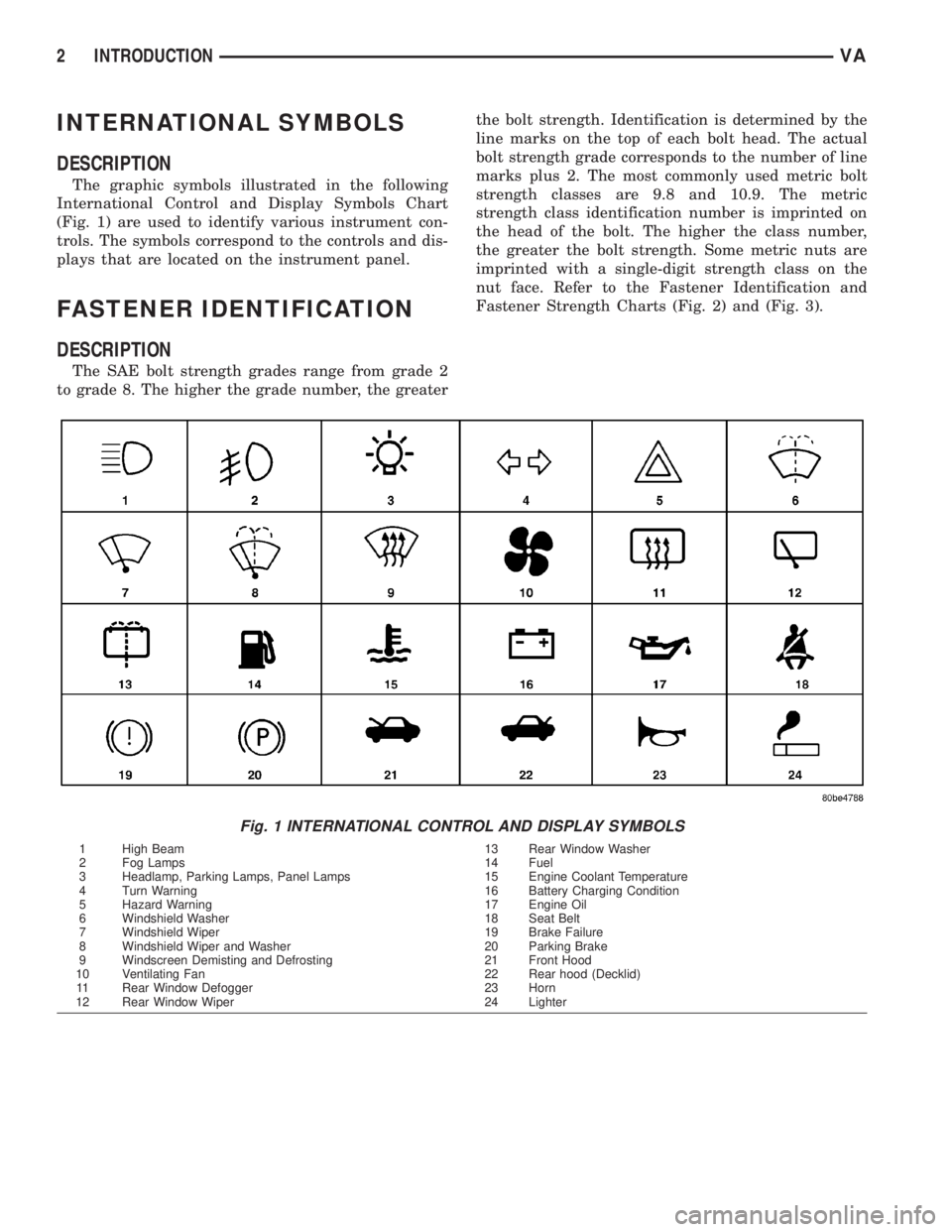
INTERNATIONAL SYMBOLS
DESCRIPTION
The graphic symbols illustrated in the following
International Control and Display Symbols Chart
(Fig. 1) are used to identify various instrument con-
trols. The symbols correspond to the controls and dis-
plays that are located on the instrument panel.
FASTENER IDENTIFICATION
DESCRIPTION
The SAE bolt strength grades range from grade 2
to grade 8. The higher the grade number, the greaterthe bolt strength. Identification is determined by the
line marks on the top of each bolt head. The actual
bolt strength grade corresponds to the number of line
marks plus 2. The most commonly used metric bolt
strength classes are 9.8 and 10.9. The metric
strength class identification number is imprinted on
the head of the bolt. The higher the class number,
the greater the bolt strength. Some metric nuts are
imprinted with a single-digit strength class on the
nut face. Refer to the Fastener Identification and
Fastener Strength Charts (Fig. 2) and (Fig. 3).
Fig. 1 INTERNATIONAL CONTROL AND DISPLAY SYMBOLS
1 High Beam 13 Rear Window Washer
2 Fog Lamps 14 Fuel
3 Headlamp, Parking Lamps, Panel Lamps 15 Engine Coolant Temperature
4 Turn Warning 16 Battery Charging Condition
5 Hazard Warning 17 Engine Oil
6 Windshield Washer 18 Seat Belt
7 Windshield Wiper 19 Brake Failure
8 Windshield Wiper and Washer 20 Parking Brake
9 Windscreen Demisting and Defrosting 21 Front Hood
10 Ventilating Fan 22 Rear hood (Decklid)
11 Rear Window Defogger 23 Horn
12 Rear Window Wiper 24 Lighter
2 INTRODUCTIONVA
Page 117 of 1232
AUDIO/VIDEO
TABLE OF CONTENTS
page page
AUDIO
SPECIAL TOOLS
AUDIO...............................1
ANTENNA BODY & CABLE
REMOVAL.............................1
INSTALLATION..........................1
INSTRUMENT PANEL ANTENNA CABLE
REMOVAL.............................1INSTALLATION..........................2
RADIO
REMOVAL.............................2
INSTALLATION..........................2
SPEAKER
REMOVAL.............................2
INSTALLATION..........................2
AUDIO
SPECIAL TOOLS
AUDIO
SPECIAL TOOL CROSS REFERENCE CHART
MB
TOOL #MILLER
TOOL #DESCRIPTION
000 589
88 63 009241 RADIO EXTRACTION
TOOL
ANTENNA BODY & CABLE
REMOVAL
(1) Disconnect and isolate the battery negative
cable.
(2) Remove the portion of the headliner over the
front seat passengers (Refer to 23 - BODY/INTERI-
OR/HEADLINER - REMOVAL).
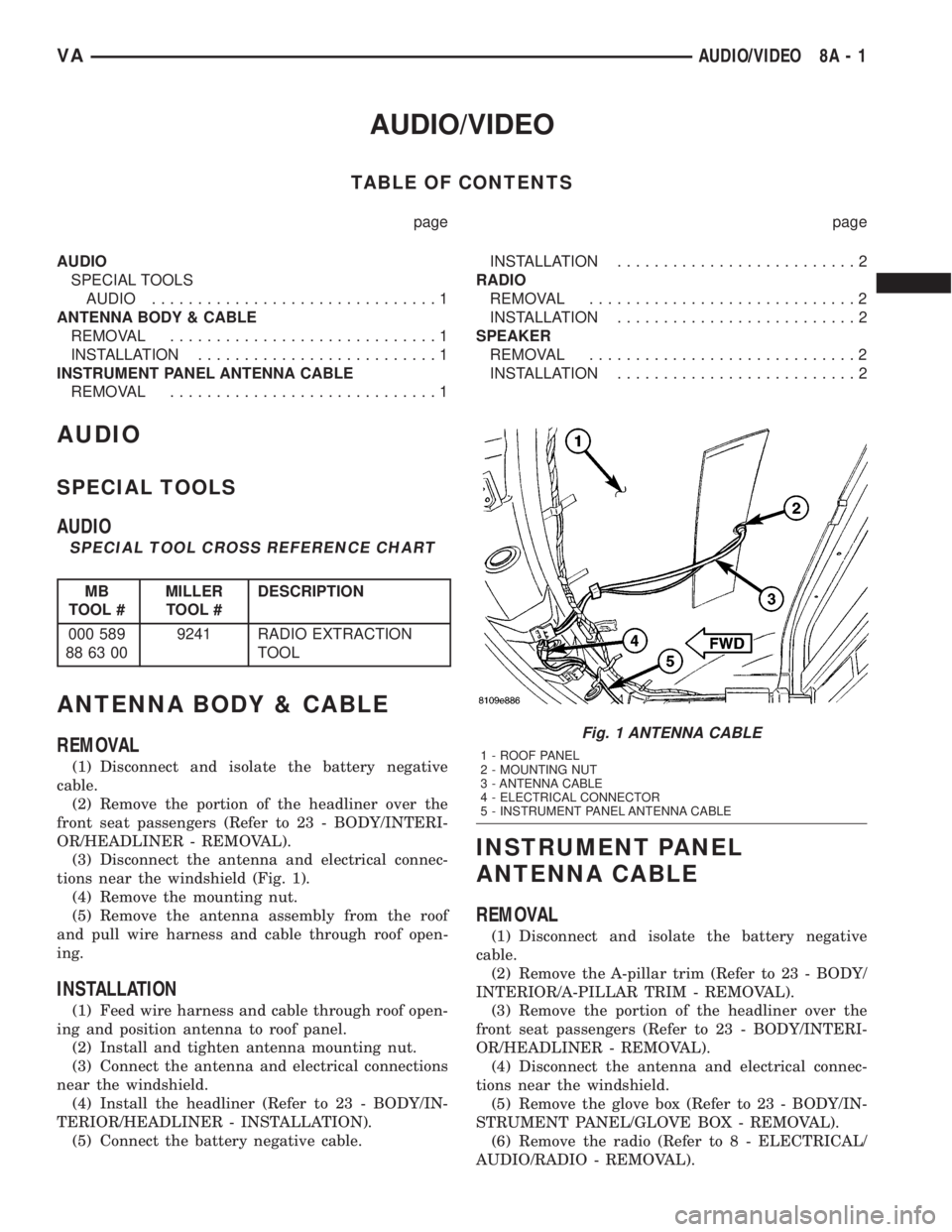
(3) Disconnect the antenna and electrical connec-
tions near the windshield (Fig. 1).
(4) Remove the mounting nut.
(5) Remove the antenna assembly from the roof
and pull wire harness and cable through roof open-
ing.
INSTALLATION
(1) Feed wire harness and cable through roof open-
ing and position antenna to roof panel.
(2) Install and tighten antenna mounting nut.
(3) Connect the antenna and electrical connections
near the windshield.
(4) Install the headliner (Refer to 23 - BODY/IN-
TERIOR/HEADLINER - INSTALLATION).
(5) Connect the battery negative cable.
INSTRUMENT PANEL
ANTENNA CABLE
REMOVAL
(1) Disconnect and isolate the battery negative
cable.
(2) Remove the A-pillar trim (Refer to 23 - BODY/
INTERIOR/A-PILLAR TRIM - REMOVAL).
(3) Remove the portion of the headliner over the
front seat passengers (Refer to 23 - BODY/INTERI-
OR/HEADLINER - REMOVAL).
(4) Disconnect the antenna and electrical connec-
tions near the windshield.
(5) Remove the glove box (Refer to 23 - BODY/IN-
STRUMENT PANEL/GLOVE BOX - REMOVAL).
(6) Remove the radio (Refer to 8 - ELECTRICAL/
AUDIO/RADIO - REMOVAL).
Fig. 1 ANTENNA CABLE
1 - ROOF PANEL
2 - MOUNTING NUT
3 - ANTENNA CABLE
4 - ELECTRICAL CONNECTOR
5 - INSTRUMENT PANEL ANTENNA CABLE
VAAUDIO/VIDEO 8A - 1
Page 118 of 1232
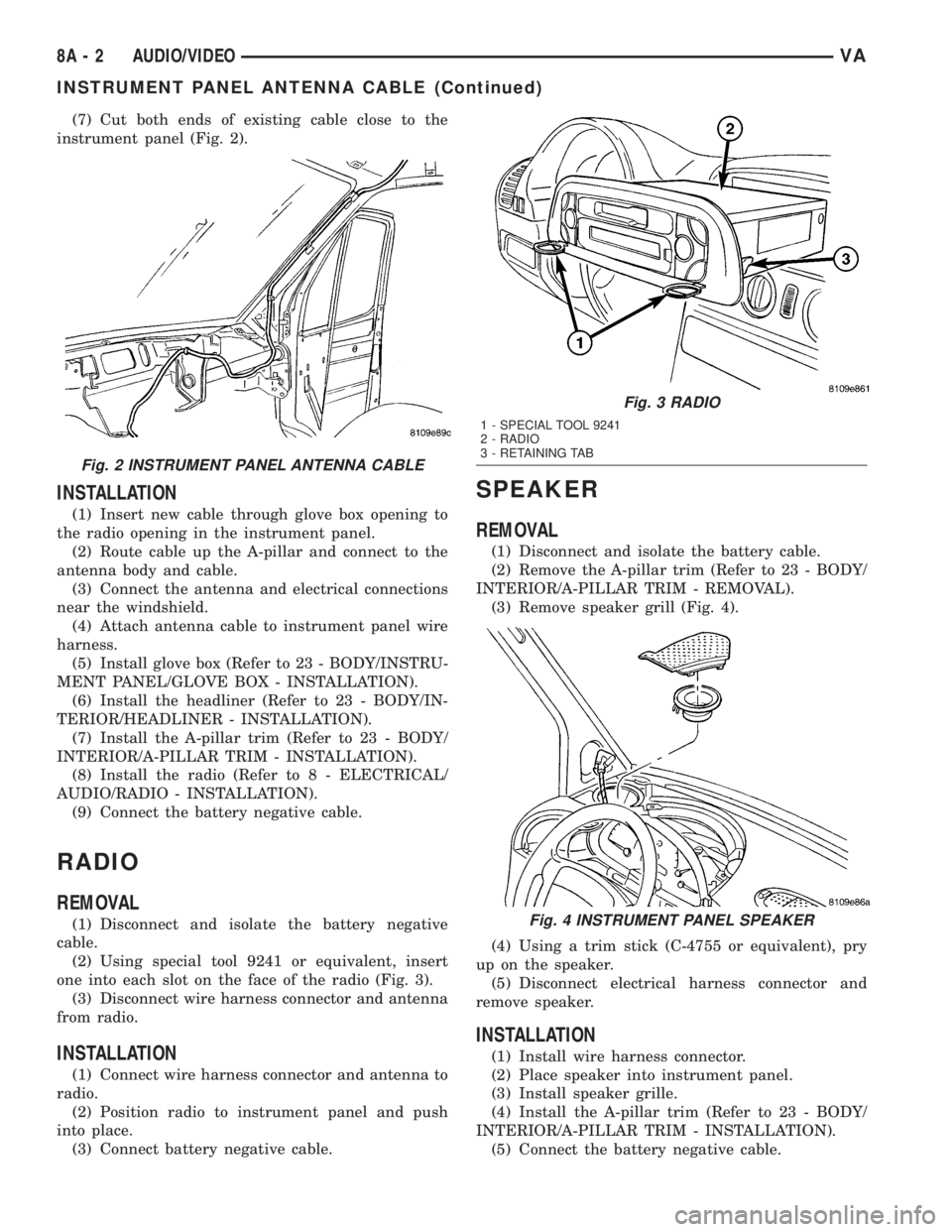
(7) Cut both ends of existing cable close to the
instrument panel (Fig. 2).
INSTALLATION
(1) Insert new cable through glove box opening to
the radio opening in the instrument panel.
(2) Route cable up the A-pillar and connect to the
antenna body and cable.
(3) Connect the antenna and electrical connections
near the windshield.
(4) Attach antenna cable to instrument panel wire
harness.
(5) Install glove box (Refer to 23 - BODY/INSTRU-
MENT PANEL/GLOVE BOX - INSTALLATION).
(6) Install the headliner (Refer to 23 - BODY/IN-
TERIOR/HEADLINER - INSTALLATION).
(7) Install the A-pillar trim (Refer to 23 - BODY/
INTERIOR/A-PILLAR TRIM - INSTALLATION).
(8) Install the radio (Refer to 8 - ELECTRICAL/
AUDIO/RADIO - INSTALLATION).
(9) Connect the battery negative cable.
RADIO
REMOVAL
(1) Disconnect and isolate the battery negative
cable.
(2) Using special tool 9241 or equivalent, insert
one into each slot on the face of the radio (Fig. 3).
(3) Disconnect wire harness connector and antenna
from radio.
INSTALLATION
(1) Connect wire harness connector and antenna to
radio.
(2) Position radio to instrument panel and push
into place.
(3) Connect battery negative cable.
SPEAKER
REMOVAL
(1) Disconnect and isolate the battery cable.
(2) Remove the A-pillar trim (Refer to 23 - BODY/
INTERIOR/A-PILLAR TRIM - REMOVAL).
(3) Remove speaker grill (Fig. 4).
(4) Using a trim stick (C-4755 or equivalent), pry
up on the speaker.
(5) Disconnect electrical harness connector and
remove speaker.
INSTALLATION
(1) Install wire harness connector.
(2) Place speaker into instrument panel.
(3) Install speaker grille.
(4) Install the A-pillar trim (Refer to 23 - BODY/
INTERIOR/A-PILLAR TRIM - INSTALLATION).
(5) Connect the battery negative cable.
Fig. 2 INSTRUMENT PANEL ANTENNA CABLE
Fig. 3 RADIO
1 - SPECIAL TOOL 9241
2 - RADIO
3 - RETAINING TAB
Fig. 4 INSTRUMENT PANEL SPEAKER
8A - 2 AUDIO/VIDEOVA
INSTRUMENT PANEL ANTENNA CABLE (Continued)
Page 120 of 1232
²Lights-On Warning- The EMIC chime tone
generator will generate repetitive chime tones at a
fast rate when either front door is opened with the
ignition switch in any position except On, and the
exterior lights are turned On. The EMIC uses inter-
nal programming and hard wired inputs from the left
(lighting) control stalk of the multi-function switch,
the ignition switch, and both front door jamb
switches to determine the current status of these
switches. This chime will continue to sound until the
exterior lighting is turned Off, until the ignition
switch is turned to the On position, or until both
front doors are closed, whichever occurs first.
²Key-In-Ignition Warning-
The EMIC chime
tone generator will generate repetitive chime tones at a
fast rate when the key is in the ignition lock cylinder,
the ignition switch is in any position except On, and
either front door is opened. The EMIC uses internal
programming and hard wired inputs from the key-in
ignition switch, the ignition switch, and both front door
jamb switches to determine the current status of these
switches. The chime will continue to sound until the key
is removed from the ignition lock cylinder, until the
ignition switch is turned to the On position, or until
both front doors are closed, whichever occurs first.
²Audible Turn Signal/Hazard Warning Sup-
port-
The EMIC contactless relay will generate repeti-
tive clicks at a slow rate during normal turn signal/
hazard warning operation, or at a fast rate when a turn
signal lamp bulb or circuit is inoperative, in concert with
the operation of the turn signal indicators in the cluster.
These clicks are designed to emulate the sound of the
opening and closing of the contact points in a conven-
tional electro-mechanical turn signal or hazard warning
flasher. The EMIC uses a hard wired input received from
the turn signal relay in the fuse block beneath the steer-
ing column through the turn signal or hazard warning
switch circuitry of the multi-function switch to determine
when to flash the turn signal indicators and activate the
contactless relay on the cluster electronic circuit board.
The turn signal clicks will continue to sound until the
turn signal switch is turned Off, or until the ignition
switch is turned to the Off position, whichever occurs
first. The hazard warning clicks will continue to sound
until the hazard warning switch is turned Off.
The EMIC provides chime service for all available
features in the chime warning system. The EMIC relies
upon its internal programming and hard wired inputs
from the front door ajar switches, the key-in ignition
switch, the ignition switch, the seat belt switch, and the
turn signal/hazard warning (multi-function) switches.
The EMIC relies upon electronic message inputs
received from other electronic modules over the CAN
data bus network to provide chime service for the low
engine oil level warning. Upon receiving the proper
inputs, the EMIC activates the chime tone generator orthe contactless relay to provide the audible warning to
the vehicle operator. The internal programming of the
EMIC determines the priority of each chime request
input that is received, as well as the rate and duration
of each tone that is to be generated. See the owner's
manual in the vehicle glove box for more information on
the features provided by the chime warning system.
The hard wired chime warning system inputs to
the EMIC, as well as other hard wired circuits for
this system may be diagnosed and tested using con-
ventional diagnostic tools and procedures. However,
conventional diagnostic methods may not prove con-
clusive in the diagnosis of the EMIC, the CAN data
bus network, or the electronic message inputs used
by the EMIC to provide chime warning system ser-
vice. The most reliable, efficient, and accurate means
to diagnose the EMIC, the CAN data bus network,
and the electronic message inputs for the chime
warning system requires the use of a DRBIIItscan
tool. Refer to the appropriate diagnostic information.
DIAGNOSIS AND TESTING - CHIME WARNING
SYSTEM
WARNING: ON VEHICLES EQUIPPED WITH AIRBAGS,
DISABLE THE SUPPLEMENTAL RESTRAINT SYSTEM
BEFORE ATTEMPTING ANY STEERING WHEEL,
STEERING COLUMN, DRIVER AIRBAG, PASSENGER
AIRBAG, SEAT BELT TENSIONER, OR INSTRUMENT
PANEL COMPONENT DIAGNOSIS OR SERVICE. DIS-
CONNECT AND ISOLATE THE BATTERY NEGATIVE
(GROUND) CABLE, THEN WAIT TWO MINUTES FOR
THE SYSTEM CAPACITOR TO DISCHARGE BEFORE
PERFORMING FURTHER DIAGNOSIS OR SERVICE.
THIS IS THE ONLY SURE WAY TO DISABLE THE SUP-
PLEMENTAL RESTRAINT SYSTEM. FAILURE TO TAKE
THE PROPER PRECAUTIONS COULD RESULT IN
ACCIDENTAL AIRBAG DEPLOYMENT AND POSSIBLE
PERSONAL INJURY.
The hard wired chime warning system inputs to
the Electro-Mechanical Instrument Cluster (EMIC),
as well as other hard wired circuits for this system
may be diagnosed and tested using conventional
diagnostic tools and procedures. However, conven-
tional diagnostic methods may not prove conclusive
in the diagnosis of the EMIC, the Controller Area
Network (CAN) data bus network, or the electronic
message inputs used by the EMIC to provide chime
warning system service. The most reliable, efficient,
and accurate means to diagnose the EMIC, the CAN
data bus network, and the electronic message inputs
for the chime warning system requires the use of a
DRBIIItscan tool. Refer to the appropriate diagnos-
tic information.
8B - 2 CHIME/BUZZERVA
CHIME/BUZZER (Continued)
Page 146 of 1232
GENERATOR
DESCRIPTION
The generator is belt-driven by the engine using a
serpentine-type drive belt. It is serviced only as a
complete assembly. If the generator fails for any rea-
son, the entire assembly must be replaced.
On certain engines, the decoupler pulley may be
replaced separately.
OPERATION
As the energized rotor begins to rotate within the
generator, the spinning magnetic field induces a cur-
rent into the windings of the stator coil. Once the
generator begins producing sufficient current, it also
provides the current needed to energize the rotor.
The stator winding connections deliver the induced
AC current to 3 positive and 3 negative diodes for
rectification. From the diodes, rectified DC current is
delivered to the vehicle electrical system through the
generator battery terminal.
Although the generators appear the same exter-
nally, different generators with different output rat-
ings are used on this vehicle. Be certain that the
replacement generator has the same output rating
and part number as the original unit. Refer to Spec-
ifications and see Generator Ratings for amperage
ratings and part numbers.
Noise emitting from the generator may be caused
by: worn, loose or defective bearings; a loose or defec-
tive drive pulley (decoupler pulley); incorrect, worn,
damaged or misadjusted fan drive belt; loose mount-
ing bolts; a misaligned drive pulley or a defective sta-
tor or diode.
An instrument panel mounted, battery charge indi-
cator lamp is used. When the key is in the on posi-
tion, the lamp will be illuminated. This is done as a
bulb check. If this lamp remains illuminated while
the engine is running, a Diagnostic Trouble Code
(DTC) has been detected for the charging system.
REMOVAL
CAUTION: DISCONNECT NEGATIVE CABLE FROM
BATTERY BEFORE REMOVING BATTERY OUTPUT
WIRE FROM GENERATOR. FAILURE TO DO SO
CAN RESULT IN INJURY.
CAUTION: Never force a belt over a pulley rim
using a screwdriver. The synthetic fiber of the belt
can be damaged.
CAUTION: When installing a serpentine accessory
drive belt, the belt MUST be routed correctly. The
water pump will be rotating in the wrong direction ifthe belt is installed incorrectly, causing the engine
to overheat. Refer to belt routing label in engine
compartment, or refer to Belt Schematics in Cooling
System.
(1) Disconnect and isolate negative battery cable.
(2) Remove generator drive belt. Refer to Cooling
System for procedure.
(3) Raise and support vehicle.
(4) Remove protective plastic cover from B+ stud
at top of generator.
(5) Remove nut securing battery output cable to
B+ terminal at top of generator.
(6) Unplug field terminal connector at rear of gen-
erator.
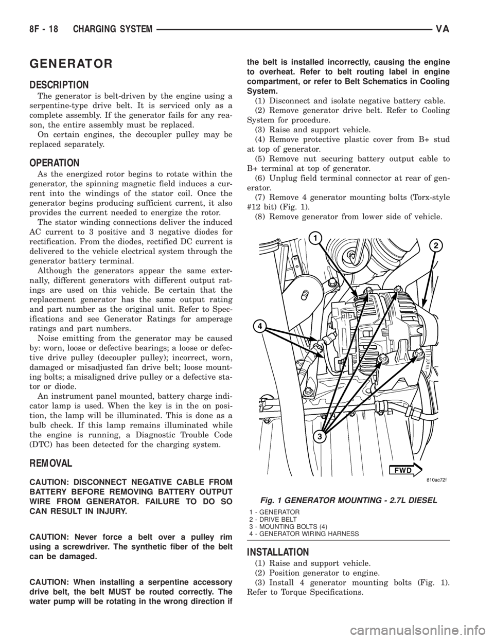
(7) Remove 4 generator mounting bolts (Torx-style
#12 bit) (Fig. 1).
(8) Remove generator from lower side of vehicle.
INSTALLATION
(1) Raise and support vehicle.
(2) Position generator to engine.
(3) Install 4 generator mounting bolts (Fig. 1).
Refer to Torque Specifications.
Fig. 1 GENERATOR MOUNTING - 2.7L DIESEL
1 - GENERATOR
2 - DRIVE BELT
3 - MOUNTING BOLTS (4)
4 - GENERATOR WIRING HARNESS
8F - 18 CHARGING SYSTEMVA
Page 154 of 1232
Starting System Diagnosis
CONDITION POSSIBLE CAUSE CORRECTION
STARTER DOES NOT
DISENGAGE.1. Starter motor
improperly installed.1. Refer to Starter Motor Removal and Installation.
Tighten starter mounting hardware to correct torque
specifications.
2. Starter relay faulty. 2. Refer to Starter Relay Diagnosis and Testing. Replace
starter relay if required.
3. Ignition switch faulty. 3. Refer to Ignition Switch and Key Lock Cylinder.
Replace ignition switch if required.
4. Starter motor faulty. 4. If all other starting system components and circuits test
OK, replace starter motor.
INSPECTION
For complete starter wiring circuit diagrams, refer
to 8, Wiring Diagrams. Before removing any unit
from starting system for repair or diagnosis, perform
the following inspections:
WARNING: ON VEHICLES EQUIPPED WITH AIR-
BAGS, REFER TO 8, PASSIVE RESTRAINT SYS-
TEMS, BEFORE ATTEMPTING ANY STEERING
WHEEL, STEERING COLUMN, OR INSTRUMENT
PANEL COMPONENT DIAGNOSIS OR SERVICE.
FAILURE TO TAKE THE PROPER PRECAUTIONS
COULD RESULT IN ACCIDENTAL AIRBAG DEPLOY-
MENT AND POSSIBLE PERSONAL INJURY.
²Battery- Visually inspect battery for indica-
tions of physical damage and loose or corroded cable
connections. Determine state-of-charge and cranking
capacity of battery. Charge or replace battery if
required. Refer toBatteryin 8, Battery.
²Ignition Switch- Visually inspect ignition
switch for indications of physical damage and loose
or corroded wire harness connections. Refer toIgni-
tion Switch and Key Lock Cylinder.
²Park/Neutral Position Switch- Visually
inspect park/neutral position switch for indications of
physical damage and loose or corroded wire harness
connections. Refer toPark/Neutral Position
Switchin 21, Transmission.
²Starter Relay- Visually inspect starter relay
for indications of physical damage and loose or cor-
roded wire harness connections.
²Starter Motor- Visually inspect starter motor
for indications of physical damage and loose or cor-
roded wire harness connections.
²Starter Solenoid- Visually inspect starter sole-
noid for indications of physical damage and loose or
corroded wire harness connections.
²Wiring- Visually inspect wire harnesses for
damage or corrosion. Repair or replace any faulty
wiring, as required. Refer to 8, Wiring Diagrams.
TESTING
COLD CRANKING TEST
For complete starter wiring circuit diagrams, refer
to 8, Wiring Diagrams. The battery must be fully-
charged and load-tested before proceeding. Refer to
Batteryin 8, Battery.
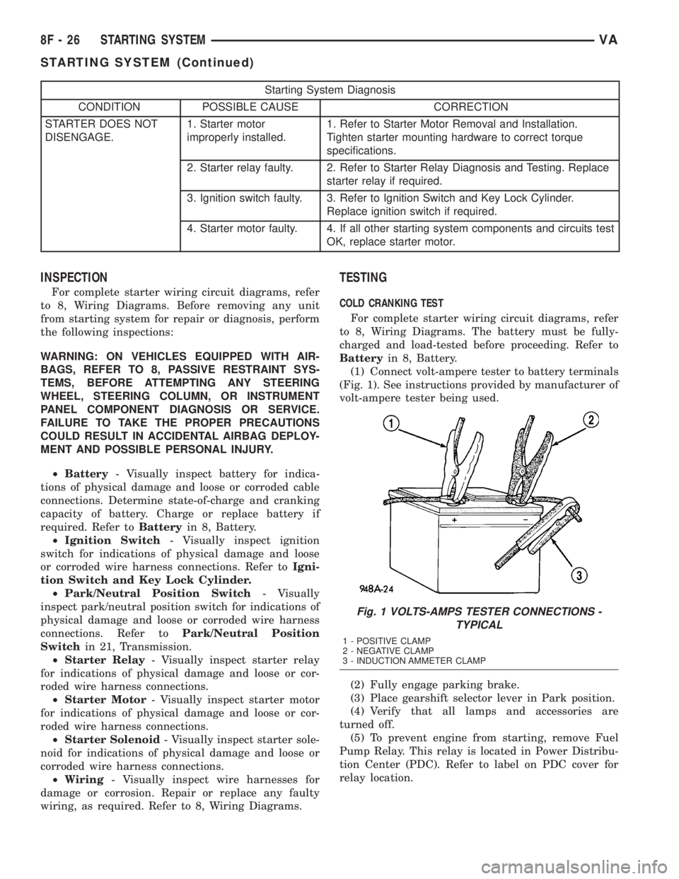
(1) Connect volt-ampere tester to battery terminals
(Fig. 1). See instructions provided by manufacturer of
volt-ampere tester being used.
(2) Fully engage parking brake.
(3) Place gearshift selector lever in Park position.
(4) Verify that all lamps and accessories are
turned off.
(5) To prevent engine from starting, remove Fuel
Pump Relay. This relay is located in Power Distribu-
tion Center (PDC). Refer to label on PDC cover for
relay location.
Fig. 1 VOLTS-AMPS TESTER CONNECTIONS -
TYPICAL
1 - POSITIVE CLAMP
2 - NEGATIVE CLAMP
3 - INDUCTION AMMETER CLAMP
8F - 26 STARTING SYSTEMVA
STARTING SYSTEM (Continued)
Page 161 of 1232
HEATED SYSTEMS
TABLE OF CONTENTS
page page
HEATED SEATS
DESCRIPTION..........................1
OPERATION............................2
DIAGNOSIS AND TESTING - HEATED SEATS . . 2
DRIVER HEATED SEAT SWITCH
DESCRIPTION..........................2
OPERATION............................2
DIAGNOSIS AND TESTING - DRIVER HEATED
SEAT SWITCH.........................2
REMOVAL.............................3
INSTALLATION..........................3
HEATED SEAT ELEMENT
DESCRIPTION..........................3
OPERATION............................3
DIAGNOSIS AND TESTING - HEATED SEAT
ELEMENT............................3
HEATED SEAT RELAY
DESCRIPTION..........................4OPERATION............................4
DIAGNOSIS AND TESTING - HEATED SEAT
RELAY...............................4
REMOVAL.............................4
INSTALLATION..........................4
HEATED SEAT SENSOR
DESCRIPTION..........................4
DIAGNOSIS AND TESTING - HEATED SEAT
SENSOR.............................4
PASSENGER HEATED SEAT SWITCH
DESCRIPTION..........................5
OPERATION............................5
DIAGNOSIS AND TESTING - PASSENGER
HEATED SEAT SWITCH.................5
REMOVAL.............................5
INSTALLATION..........................5
HEATED SEATS
DESCRIPTION
Individually controlled, electrically heated front
seats are available factory-installed optional equip-
ment on this model. Vehicles with this option can be
visually identified by the two separate heated seat
switches mounted in the instrument panel. The
heated seat system allows the front seat driver and
passenger to select from two different levels of sup-
plemental electrical seat heating, or no seat heating
to suit their individual comfort requirements. The
heated seat system for this vehicle includes the fol-
lowing major components, which are described in fur-
ther detail later in this section:
²Heated Seat Elements- Four heated seat ele-
ments are used per vehicle, two for each front seat.
One heating element in the seat back and one in the
seat cushion. The heated seat sensor is integral to
the seat cushion heating element. The heated seat
elements are integral to the front seat and seat back
cushions. Refer to heated seat elements later in this
section for additional information.²Heated Seat Relay- One heated seat relay is
used per vehicle. The relay is located in the fuse
block and is responsible for distributing the voltage
(B+) to the heated seat elements.
²Heated Seat Sensors- Two heated seat sen-
sors are used per vehicle, one for each front seat. The
heated seat sensors are integral to each of the heated
seat element assemblies. Refer to heated seat sensor
later in this section for additional information.
²Heated Seat Switches- Two heated seat
switches are used per vehicle, one for each front seat.
The switches are mounted in the instrument panel.
Refer to heated seat switches later in this section for
additional information.
Hard wired circuitry connects the heated seat sys-
tem components to each other through the electrical
system of the vehicle. Refer to Wiring for additional
information. The wiring information includes wiring
diagrams, proper wire and connector repair proce-
dures, further details on wire harness routing and
retention, as well as pin-out and location views for
the various wire harness connectors, splices and
grounds.
VAHEATED SYSTEMS 8G - 1
Page 163 of 1232
REMOVAL
(1) Disconnect and isolate the negative battery
cable.
(2) Remove the gear selector bezel trim. Refer to
the Body section for the procedure.
(3) Remove the storage bin. Refer to the Body sec-
tion for the procedure.
(4) Remove the switch bezel retaining screw and
remove the switch bezel from the instrument panel.
Refer to the Body section for the procedure.
(5) Disconnect electrical connections.
(6) Working from the underside of the switch, gen-
tly rock the switch back and forth out of its mounting
location in the switch bezel.
INSTALLATION
(1) Install the heated seat switch in its mounting
location in the switch bezel.
(2) Connect electrical connections.
(3) Position the switch bezel and install the retain-
ing screw. Refer to the Body section for the proce-
dure.
(4) Install the storage bin. Refer to the Body sec-
tion for the procedure.
(5) Install the gear selector bezel trim. Refer to the
Body section for the procedure.
(6) Connect the negative battery cable.
HEATED SEAT ELEMENT
DESCRIPTION
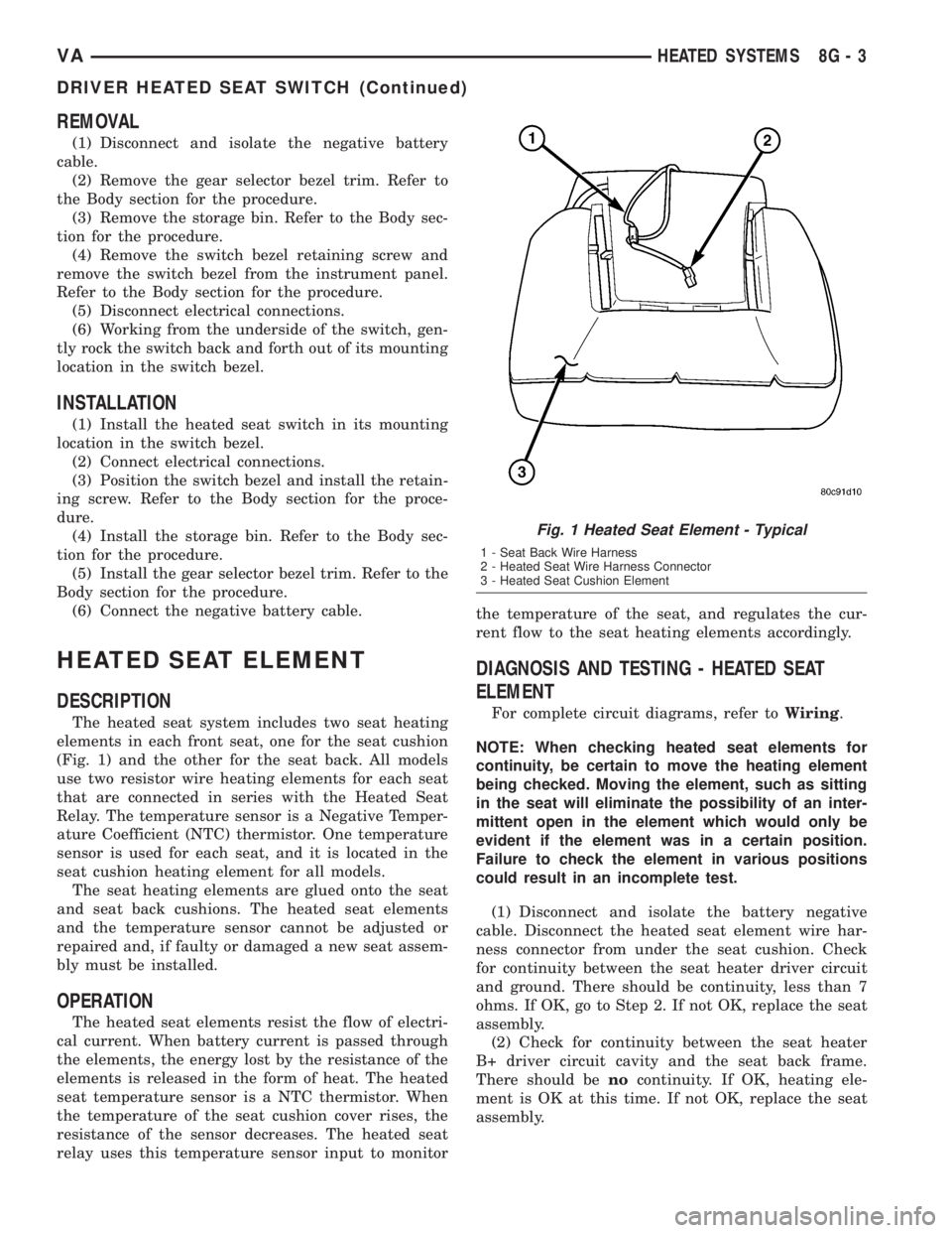
The heated seat system includes two seat heating
elements in each front seat, one for the seat cushion
(Fig. 1) and the other for the seat back. All models
use two resistor wire heating elements for each seat
that are connected in series with the Heated Seat
Relay. The temperature sensor is a Negative Temper-
ature Coefficient (NTC) thermistor. One temperature
sensor is used for each seat, and it is located in the
seat cushion heating element for all models.
The seat heating elements are glued onto the seat
and seat back cushions. The heated seat elements
and the temperature sensor cannot be adjusted or
repaired and, if faulty or damaged a new seat assem-
bly must be installed.
OPERATION
The heated seat elements resist the flow of electri-
cal current. When battery current is passed through
the elements, the energy lost by the resistance of the
elements is released in the form of heat. The heated
seat temperature sensor is a NTC thermistor. When
the temperature of the seat cushion cover rises, the
resistance of the sensor decreases. The heated seat
relay uses this temperature sensor input to monitorthe temperature of the seat, and regulates the cur-
rent flow to the seat heating elements accordingly.
DIAGNOSIS AND TESTING - HEATED SEAT
ELEMENT
For complete circuit diagrams, refer toWiring.
NOTE: When checking heated seat elements for
continuity, be certain to move the heating element
being checked. Moving the element, such as sitting
in the seat will eliminate the possibility of an inter-
mittent open in the element which would only be
evident if the element was in a certain position.
Failure to check the element in various positions
could result in an incomplete test.
(1) Disconnect and isolate the battery negative
cable. Disconnect the heated seat element wire har-
ness connector from under the seat cushion. Check
for continuity between the seat heater driver circuit
and ground. There should be continuity, less than 7
ohms. If OK, go to Step 2. If not OK, replace the seat
assembly.
(2) Check for continuity between the seat heater
B+ driver circuit cavity and the seat back frame.
There should benocontinuity. If OK, heating ele-
ment is OK at this time. If not OK, replace the seat
assembly.
Fig. 1 Heated Seat Element - Typical
1 - Seat Back Wire Harness
2 - Heated Seat Wire Harness Connector
3 - Heated Seat Cushion Element
VAHEATED SYSTEMS 8G - 3
DRIVER HEATED SEAT SWITCH (Continued)
Page 165 of 1232
PASSENGER HEATED SEAT
SWITCH
DESCRIPTION
The heated seat switches are located on the instru-
ment panel, in the accessory switch bezel. The two,
momentary rocker type switches provide a signal to
the Heated Seat Relay through separate hard wired
circuits. Each switch contains two light emitting
diodes (LED), one for each High and Low setting to
let the occupant know that the seat heater system is
on.
The heated seat switches and their LED's cannot
be repaired. If either switch is faulty or damaged the
entire switch must be replaced.
OPERATION
There are three modes that can be selected with
each of the heated seat switches: Off, Low, and High.
When the top of the switch rocker is depressed, the
low mode is selected and the low mode LED indicator
illuminates. Depressing the top of the switch rocker a
second time will turn the heated seat to Off. This
same process is repeated for High heat setting. The
heated seats will automatically return to the Off
mode anytime the vehicle ignition switch is turned
Off.
Both switches provide separate hard wire inputs to
the Heated Seat Relay to indicate the selected mode.
The Heated Seat Relay responds to the heated seat
switch messages by controlling the output to the seat
heater elements of the selected seat.
DIAGNOSIS AND TESTING - PASSENGER
HEATED SEAT SWITCH
For circuit description and diagrams, refer toWir-
ing.
(1) Inspect the Heated Seat Switches for apparent
damage or sticking/binding and replace if required.
Refer to Heated Seat Switch Removal and Installa-
tion in this section.
(2) Replace the heated seat switch with a known
good unit and retest the heated seat system.
REMOVAL
(1) Disconnect and isolate the negative battery
cable.
(2) Remove the gear selector bezel trim. Refer to
the Body section for the procedure.
(3) Remove the storage bin. Refer to the Body sec-
tion for the procedure.
(4) Remove the switch bezel retaining screw and
remove the switch bezel from the instrument panel.
Refer to the Body section for the procedure.
(5) Disconnect electrical connections.
(6) Working from the underside of the switch, gen-
tly rock the switch back and forth out of its mounting
location in the switch bezel.
INSTALLATION
(1) Install the heated seat switch in its mounting
location in the switch bezel.
(2) Connect electrical connections.
(3) Position the switch bezel and install the retain-
ing screw. Refer to the Body section for the proce-
dure.
(4) Install the storage bin. Refer to the Body sec-
tion for the procedure.
(5) Install the gear selector bezel trim. Refer to the
Body section for the procedure.
(6) Connect the negative battery cable.
VAHEATED SYSTEMS 8G - 5
Page 172 of 1232
INSTRUMENT CLUSTER
DESCRIPTION
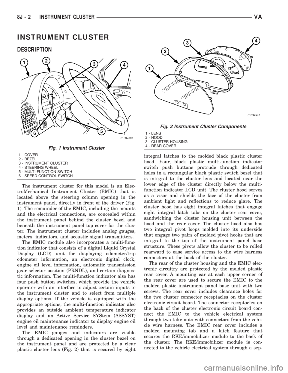
The instrument cluster for this model is an Elec-
troMechanical Instrument Cluster (EMIC) that is
located above the steering column opening in the
instrument panel, directly in front of the driver (Fig.
1). The remainder of the EMIC, including the mounts
and the electrical connections, are concealed within
the instrument panel behind the cluster bezel and
beneath the instrument panel top cover for the clus-
ter. The instrument cluster includes analog gauges,
meters, indicators, and acoustic signal transmitters.
The EMIC module also incorporates a multi-func-
tion indicator that consists of a digital Liquid Crystal
Display (LCD) unit for displaying odometer/trip
odometer information, an electronic digital clock,
engine oil level information, automatic transmission
gear selector position (PRNDL), and certain diagnos-
tic information. The multi-function indicator also has
four push button switches, which provide the vehicle
operator with an interface to adjust certain inputs to
the instrument cluster and to select from multiple
display options. If the vehicle is equipped with the
appropriate options, the multi-function indicator also
provides an outside ambient temperature indicator
display and an Active Service SYStem (ASSYST)
engine oil maintenance indicator to display engine oil
level and maintenance reminders.
The EMIC gauges and indicators are visible
through a dedicated opening in the cluster bezel on
the instrument panel and are protected by a clear
plastic cluster lens (Fig. 2) that is secured by eightintegral latches to the molded black plastic cluster
hood. Four, black plastic multi-function indicator
switch push buttons protrude through dedicated
holes in a rectangular black plastic switch bezel that
is integral to the cluster lens and located near the
lower edge of the cluster directly below the multi-
function indicator LCD unit. The cluster hood serves
as a visor and shields the face of the cluster from
ambient light and reflections to reduce glare. The
cluster hood has eight integral latches that engage
eight integral latch tabs on the cluster rear cover,
sandwiching the cluster housing unit between the
hood and the rear cover. The cluster hood also has
two integral pivot loops molded into its underside
that engage two pairs of molded pivot hooks that are
integral to the top of the instrument panel base
structure. These pivots allow the cluster to be rolled
rearward to ease service access to the wire harness
connectors at the back of the cluster.
The rear of the cluster housing and the EMIC elec-
tronic circuitry are protected by the molded plastic
rear cover. A mounting ear at each upper corner of
the rear cover are used to secure the EMIC to the
molded plastic instrument panel base unit with two
screws. The rear cover includes clearance holes for
the two cluster connector receptacles on the cluster
electronic circuit board. The connector receptacles on
the back of the cluster electronic circuit board con-
nect the EMIC to the vehicle electrical system
through two take outs with connectors from the vehi-
cle wire harness. The EMIC rear cover includes a
molded mounting tab and a latch feature that
secures the RKE/immobilizer module to the back of
the cluster. The RKE/immobilizer module is con-
nected to the vehicle electrical system through a sep-
Fig. 1 Instrument Cluster
1 - COVER
2 - BEZEL
3 - INSTRUMENT CLUSTER
4 - STEERING WHEEL
5 - MULTI-FUNCTION SWITCH
6 - SPEED CONTROL SWITCH
Fig. 2 Instrument Cluster Components
1 - LENS
2 - HOOD
3 - CLUSTER HOUSING
4 - REAR COVER
8J - 2 INSTRUMENT CLUSTERVA