Oxygen Sensor MERCEDES-BENZ SPRINTER 2006 User Guide
[x] Cancel search | Manufacturer: MERCEDES-BENZ, Model Year: 2006, Model line: SPRINTER, Model: MERCEDES-BENZ SPRINTER 2006Pages: 2305, PDF Size: 48.12 MB
Page 1420 of 2305

Component Page
Interior Lamp-Right................. 8W-80-58
Interior Light Switch................ 8W-80-59
Interior Light Switch-Driver........... 8W-80-59
Interior Light Switch-Passenger........ 8W-80-59
Interior Light Switch-Rear............ 8W-80-60
Interior Lighting Connector........... 8W-80-60
Intrusion Sensor No. 1............... 8W-80-60
Intrusion Sensor No. 2............... 8W-80-60
Intrusion Sensor No. 3............... 8W-80-61
Kick Down Switch.................. 8W-80-61
Lateral Acceleration Sensor........... 8W-80-61
License Plate Lamp No. 1............. 8W-80-61
License Plate Lamp No. 2............. 8W-80-61
Locker Switch No. 1................. 8W-80-62
Locker Switch No. 2................. 8W-80-62
Low Fuel Pressure Sensor............ 8W-80-62
Map/Reading Lamp Switch............ 8W-80-62
Marker Lamp Connector............. 8W-80-63
Marker Lamp No. 1-Left Front......... 8W-80-63
Marker Lamp No. 1-Right Front....... 8W-80-63
Marker Lamp No. 2-Left Front......... 8W-80-63
Marker Lamp No. 2-Right Front....... 8W-80-64
Marker Lamp-Left Center............ 8W-80-64
Marker Lamp-Left Rear.............. 8W-80-64
Marker Lamp-Right Center........... 8W-80-64
Marker Lamp-Right Rear............. 8W-80-64
Mass Air Flow Sensor................ 8W-80-65
Master Door Lock Switch............. 8W-80-65
Metering Pump..................... 8W-80-65
Microphone Connector............... 8W-80-65
Oxygen Sensor (OBD)................ 8W-80-66
Panic Alarm Switch................. 8W-80-66
Parking Brake Switch............... 8W-80-66
Power Mirror Motor-Driver........... 8W-80-67
Power Mirror Motor-Passenger......... 8W-80-67
Power Mirror Switch................ 8W-80-67
Power Window Motor-Driver.......... 8W-80-67
Power Window Motor-Passenger........ 8W-80-68
Power Window Switch-Driver.......... 8W-80-68
Power Window Switch-master......... 8W-80-68
Power Window Switch-Passenger....... 8W-80-68
Radio Antenna..................... 8W-80-69
Radio C1.......................... 8W-80-69
Radio C2.......................... 8W-80-69
Radio/Cellular Antenna.............. 8W-80-69
Rain Sensor....................... 8W-80-70
Rain Sensor Control Module........... 8W-80-70
Reading Lamp Connector............. 8W-80-71
Recirculated Air Solenoid Valve........ 8W-80-71
Refrigerant Pressure Sensor........... 8W-80-71
Remote Keyless Entry Antenna........ 8W-80-71
Rollover Switch Assembly............. 8W-80-71
Roof A/C Control Module............. 8W-80-72
Roof A/C Switch.................... 8W-80-72Component Page
Roof A/C Temperature Setting Control . . . 8W-80-72
Roof Fan Motor..................... 8W-80-73
Roof Fan Switch.................... 8W-80-73
Roof Thermotronic Control Module...... 8W-80-73
Seat Belt Switch.................... 8W-80-74
Seat Belt Tensioner-Driver............ 8W-80-74
Seat Belt Tensioner-Passenger......... 8W-80-74
Security System Module C1........... 8W-80-75
Security System Module C2........... 8W-80-75
Sentry Key Remote Entry Module
(SKREEM)...................... 8W-80-76
Shifter Assembly................... 8W-80-76
Siren............................. 8W-80-76
SKREEM Transponder............... 8W-80-77
Speaker-Left Front Door Assembly C1 . . . 8W-80-77
Speaker-Left Front Door Assembly C2 . . . 8W-80-77
Speaker-Left Rear.................. 8W-80-77
Speaker-Right Front Door............ 8W-80-77
Speaker-Right Rear................. 8W-80-78
Speed Control Switch................ 8W-80-78
Steering Angle Sensor............... 8W-80-78
Tail Lamp Assembly-Left............. 8W-80-78
Tail Lamp Assembly-Right............ 8W-80-79
TCS Switch (ASR).................. 8W-80-79
Towing/intrusion Sensor On/Off Switch . . 8W-80-79
Trailer Tow Connector............... 8W-80-80
Trailer Tow Control Module C1 (Except
Retrofit)........................ 8W-80-80
Trailer Tow Control Module C1 (retrofit) . 8W-80-80
Trailer Tow Control Module C2 (Except
Retrofit)........................ 8W-80-81
Transmission Control Module C1....... 8W-80-81
Transmission Control Module C2....... 8W-80-81
Turn Signal No. 1-Left Front.......... 8W-80-82
Turn Signal No. 1-Right Front......... 8W-80-82
Turn Signal No. 2-Left Front.......... 8W-80-82
Turn Signal No. 2-Right Front......... 8W-80-82
Warm Air Auxiliary Heater Assembly
C1............................. 8W-80-83
Warm Air Auxiliary Heater Assembly
C2............................. 8W-80-83
Washer Pump Motor-Front............ 8W-80-83
Water Cycle Valve................... 8W-80-83
Water In Fuel Sensor................ 8W-80-84
Wheel Speed Sensor-Left Front........ 8W-80-84
Wheel Speed Sensor-Left Rear......... 8W-80-84
Wheel Speed Sensor-Right Front....... 8W-80-84
Wheel Speed Sensor-Right Rear........ 8W-80-84
Window Defogger Module-Rear......... 8W-80-85
Window Defogger Switch-Rear......... 8W-80-85
Window Defogger-Left Rear........... 8W-80-86
Window Defogger-Right Rear.......... 8W-80-86
Wiper Motor-Front.................. 8W-80-86
VA8W-80 CONNECTOR PIN-OUTS 8W - 80 - 3
Page 1483 of 2305

OXYGEN SENSOR (OBD)
CAV CIRCUIT FUNCTION
1 20DG/BK O2 1/1 PUMP CELL SIGNAL
2 20GY/WT O2 1/1 VIRTUAL GROUND
3 20GY/BL O2 1/1 HEATER CONTROL
4 20RD/DG FUSED ENGINE CONTROL RELAY OUTPUT
5 20DG/YL O2 1/1 PUMP CELL CONTROL
6 20GY O2 1/1 SENSOR CELL SIGNAL
PANIC ALARM SWITCH - BLACK
CAV CIRCUIT FUNCTION
1 18GY/DG/RD LAMP DRIVER
2- -
3 18BR GROUND
4- -
5- -
6- -
7 18GY/WT PANIC SWITCH SENSE
8- -
9- -
10 18BR GROUND
PARKING BRAKE SWITCH
CAV CIRCUIT FUNCTION
1 20BR/BK PARK BRAKE INDICATOR SIGNAL
2 16BR GROUND
3- -
4- -
5- -
6- -
7- -
8- -
9- -
10 - -
8W - 80 - 66 8W-80 CONNECTOR PIN-OUTSVA
Page 1510 of 2305

CONNECTOR NAME/NUMBER COLOR LOCATION FIG.
License Plate Lamp No. 2 On Rear Of Vehicle 53
Locker Switch No. 1 BK Under Body-Front N/S
Locker Switch No. 2 BK Under Body-Rear 51
Low Fuel Pressure Sensor BK Engine Compartment 12,14
Low Pressure Switch Roof A/C Unit 39
Map/Reading Lamp Switch BK Instrument Panel N/S
Marker Lamp Connector K NS
Marker Lamp No.1-Left Front BK Front Of Vehicle-Left Side N/S
Marker Lamp No.1-Right Front BK Front Of Vehicle-Left Side N/S
Marker Lamp No.2-Left Front BK 5
Marker Lamp No.2-Right Front BK 5
Marker Lamp-Left Center BK Front Of Vehicle-Center Left
Side53
Marker Lamp-Left Rear BK Rear Of Vehicle-Left Side 53
Marker Lamp-Right Center BK Front Of Vehicle-Center
Right Side53
Marker Lamp-Right Rear BK Rear Of Vehicle -Right Side 53
Mass Air Flow Sensor BK Engine Compartment 11
Master Door Lock Switch BK Center Of Instrument Panel 20
Metering Pump BK Instrument Panel 27
Microphone Connector Instrument Panel N/S
Multi-Function Switch Steering Wheel 24
Optional Equipment Relay (Relay Block) Under Driver Seat 23
Oxygen Sensor (OBD) BK 6
Panic Alarm Switch BK Instrument Panel 20
Parking Brake Switch BK Under Instrument Panel N/S
Power Mirror Motor-Driver BK In Driver Door 27
Power Mirror Motor-Passenger BK In Passenger Door 27
Power Mirror Switch BK 23
Power Window Motor-Driver BK 44
Power Window Motor-Passenger BK 44
Power Window Switch-Driver BK 23
Power Window Switch-Master BK 23
Power Window Switch-Passenger BK 6
Radio Antenna Behind Radio 48
Radio C1 BK Behind Radio 20
Radio C2 BK Behind Radio 20
Radio/Cellular Antenna Behind Radio 48
Rain Sensor Front Center Roof 25
Reading Lamp Connector WT Instrument Panel N/S
Recirculated Air Solenoid Valve BK Underhood Right (To The
Instrument Panel)10
Refrigerant Pressure Sensor Engine Compartment-Left
Front8,10
VA8W-91 CONNECTOR/GROUND/SPLICE LOCATION 8W - 91 - 7
Page 1726 of 2305
INSTALLATION
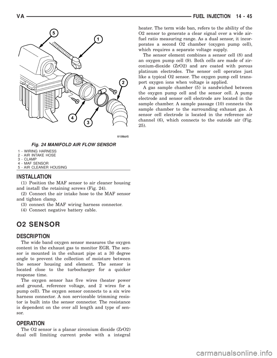
(1) Position the MAF sensor to air cleaner housing
and install the retaining screws (Fig. 24).
(2) Connect the air intake hose to the MAF sensor
and tighten clamp.
(3) connect the MAF wiring harness connector.
(4) Connect negative battery cable.
O2 SENSOR
DESCRIPTION
The wide band oxygen sensor measures the oxygen
content in the exhaust gas to monitor EGR. The sen-
sor is mounted in the exhaust pipe at a 30 degree
angle to prevent the collection of moisture between
the sensor housing and element. The sensor is
located close to the turbocharger for a quicker
response time.
The oxygen sensor has five wires (heater power
and ground, reference voltage, and 2 wires for a
pump cell). The oxygen sensor connects to a six wire
harness connector. A non serviceable trimming resis-
tor is built into the sensor connector. The resistance
is dependent on the over all length and type of sen-
sor.
OPERATION
The O2 sensor is a planar zirconium dioxide (ZrO2)
dual cell limiting current probe with a integralheater. The term wide ban, refers to the ability of the
O2 sensor to generate a clear signal over a wide air-
fuel ratio measuring range. As a dual sensor, it incor-
porates a second O2 chamber (oxygen pump cell),
which requires a separate voltage supply.
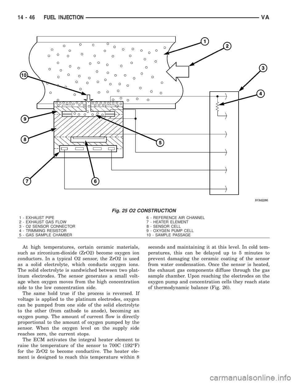
The sensor element combines a sensor cell (8) and
an oxygen pump cell (9). Both cells are made of zir-
conium-dioxide (ZrO2) and are coated with porous
platinum electrodes. The sensor cell operates just
like a typical O2 sensor. The oxygen pump cell trans-
port oxygen ions when voltage is applied.
A gas sample chamber (5) is sandwiched between
the oxygen pump cell and the sensor cell. A pump
electrode and sensor cell electrode are located in the
sample chamber. A sample passage (10) connects the
sample chamber to the surrounding exhaust gas. A
sensor cell electrode is located in the reference air
channel (6), which connects to the outside air (Fig.
25).
Fig. 24 MANIFOLD AIR FLOW SENSOR
1 - WIRING HARNESS
2 - AIR INTAKE HOSE
3 - CLAMP
4 - MAF SENSOR
5 - AIR CLEANER HOUSING
VAFUEL INJECTION 14 - 45
Page 1727 of 2305
At high temperatures, certain ceramic materials,
such as zirconium-dioxide (ZrO2) become oxygen ion
conductors. In a typical O2 sensor, the ZrO2 is used
as a solid electrolyte, which conducts oxygen ions.
The solid electrolyte is sandwiched between two plat-
inum electrodes. The sensor generates a small volt-
age when oxygen moves from the high concentration
side to the low concentration side.
The same hold true if the process is reversed. If
voltage is applied to the platinum electrodes, oxygen
can be pumped from one side of the solid electrolyte
to the other (from cathode to anode), becoming an
oxygen pump. The amount of current flow is directly
proportional to the amount of oxygen pumped by the
sensor. When the oxygen level on the supply side
reaches zero, the current stops.
The ECM activates the integral heater element to
raise the temperature of the sensor to 700C (192ÉF)
for the ZrO2 to become conductive. The heater ele-
ment is designed to reach this temperature within 8seconds and maintaining it at this level. In cold tem-
peratures, this can be delayed up to 5 minutes to
prevent damaging the ceramic coating of the sensor
from water condensation. Once the sensor is heated,
the exhaust gas components diffuse through the gas
sample chamber. Upon reaching the electrodes on the
oxygen pump and concentration cells they reach state
of thermodynamic balance (Fig. 26).
Fig. 25 O2 CONSTRUCTION
1 - EXHAUST PIPE 6 - REFERENCE AIR CHANNEL
2 - EXHAUST GAS FLOW 7 - HEATER ELEMENT
3 - O2 SENSOR CONNECTOR 8 - SENSOR CELL
4 - TRIMMING RESISTOR 9 - OXYGEN PUMP CELL
5 - GAS SAMPLE CHAMBER 10 - SAMPLE PASSAGE
14 - 46 FUEL INJECTIONVA
Page 1728 of 2305
The sensor cell measures the difference between
the oxygen concentration in the gas sample chamber
and the oxygen concentration in the outside air from
the reference air channel. A small voltage is gener-
ated across the sensor, which is proportional to the
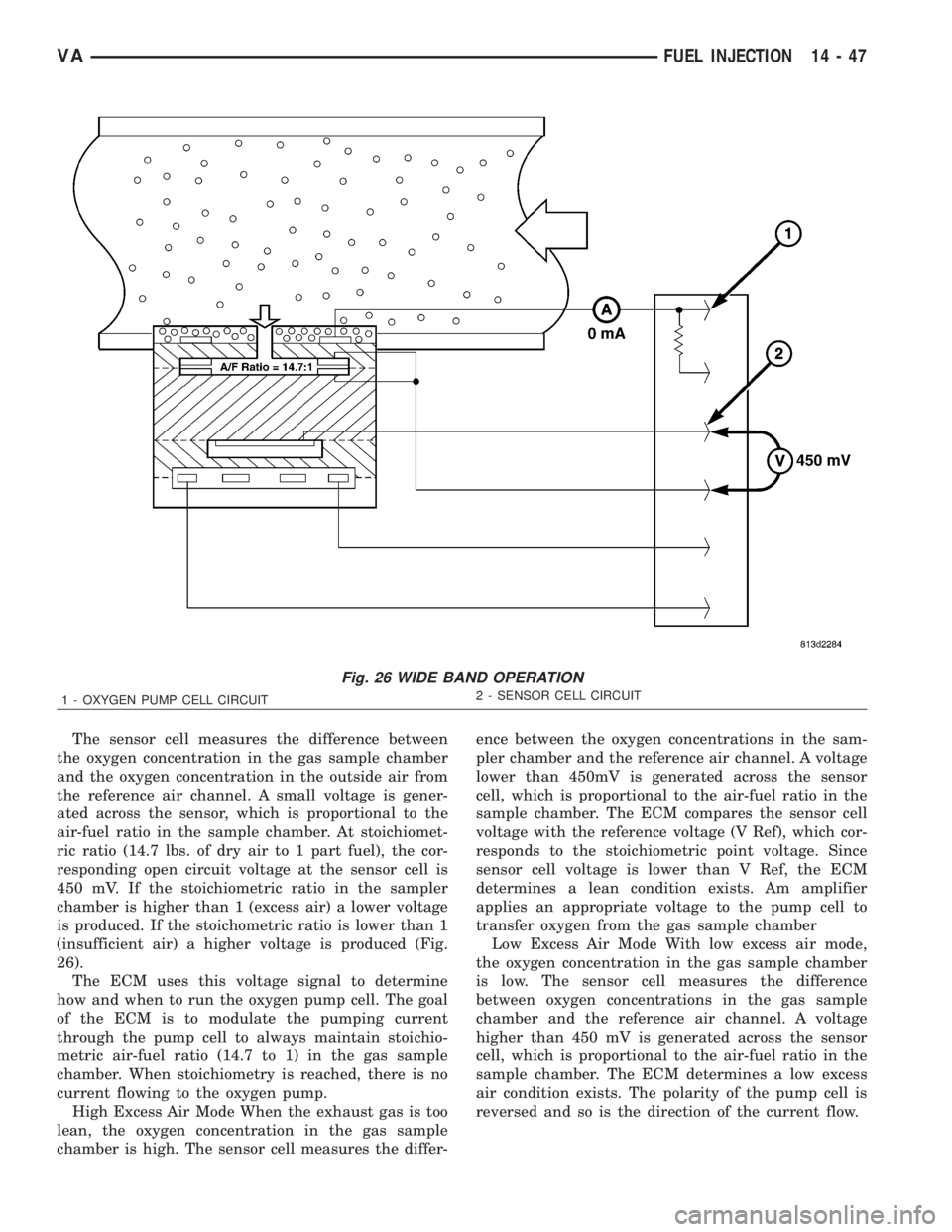
air-fuel ratio in the sample chamber. At stoichiomet-
ric ratio (14.7 lbs. of dry air to 1 part fuel), the cor-
responding open circuit voltage at the sensor cell is
450 mV. If the stoichiometric ratio in the sampler
chamber is higher than 1 (excess air) a lower voltage
is produced. If the stoichometric ratio is lower than 1
(insufficient air) a higher voltage is produced (Fig.
26).
The ECM uses this voltage signal to determine
how and when to run the oxygen pump cell. The goal
of the ECM is to modulate the pumping current
through the pump cell to always maintain stoichio-
metric air-fuel ratio (14.7 to 1) in the gas sample
chamber. When stoichiometry is reached, there is no
current flowing to the oxygen pump.
High Excess Air Mode When the exhaust gas is too
lean, the oxygen concentration in the gas sample
chamber is high. The sensor cell measures the differ-ence between the oxygen concentrations in the sam-
pler chamber and the reference air channel. A voltage
lower than 450mV is generated across the sensor
cell, which is proportional to the air-fuel ratio in the
sample chamber. The ECM compares the sensor cell
voltage with the reference voltage (V Ref), which cor-
responds to the stoichiometric point voltage. Since
sensor cell voltage is lower than V Ref, the ECM
determines a lean condition exists. Am amplifier
applies an appropriate voltage to the pump cell to
transfer oxygen from the gas sample chamber
Low Excess Air Mode With low excess air mode,
the oxygen concentration in the gas sample chamber
is low. The sensor cell measures the difference
between oxygen concentrations in the gas sample
chamber and the reference air channel. A voltage
higher than 450 mV is generated across the sensor
cell, which is proportional to the air-fuel ratio in the
sample chamber. The ECM determines a low excess
air condition exists. The polarity of the pump cell is
reversed and so is the direction of the current flow.
Fig. 26 WIDE BAND OPERATION
1 - OXYGEN PUMP CELL CIRCUIT2 - SENSOR CELL CIRCUIT
VAFUEL INJECTION 14 - 47
Page 1729 of 2305
REMOVAL
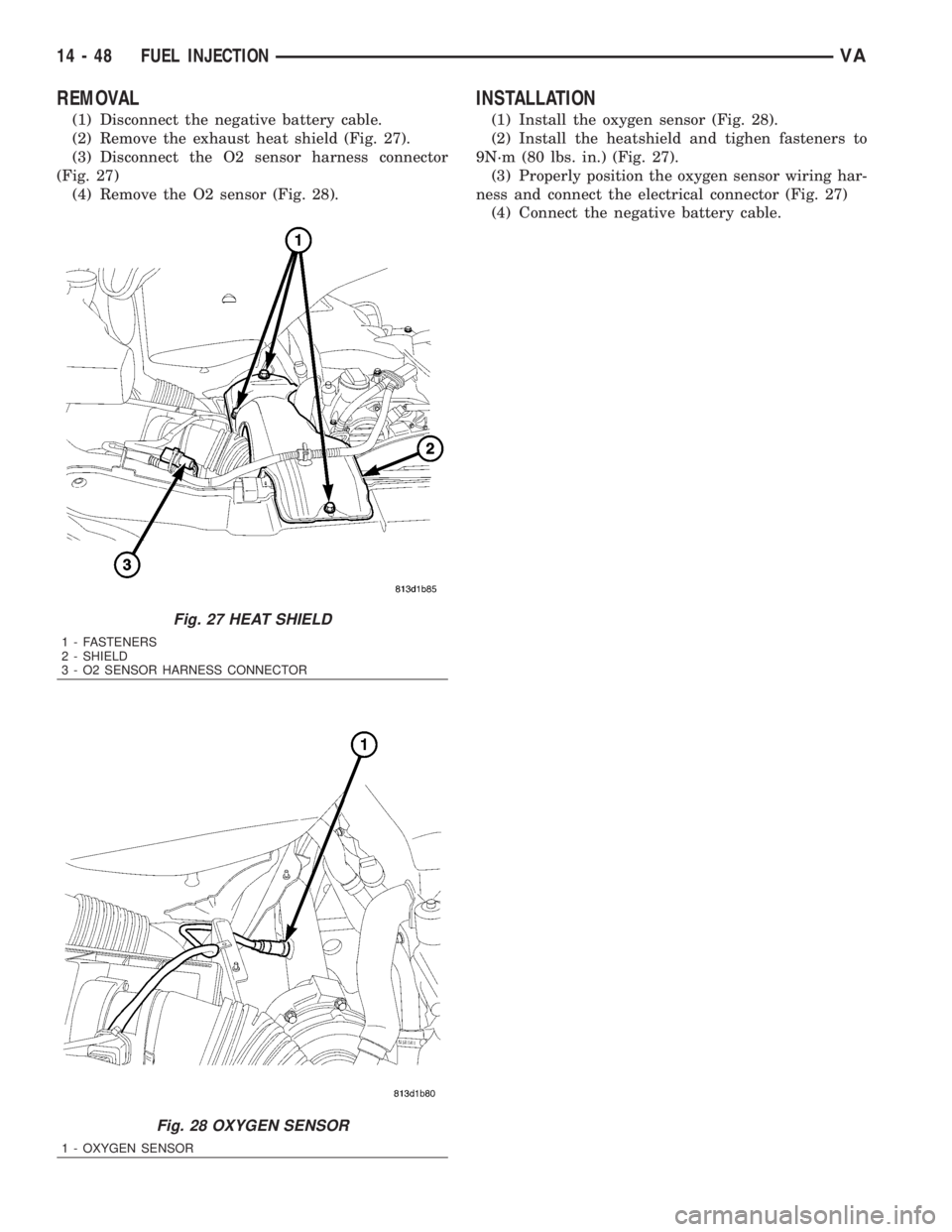
(1) Disconnect the negative battery cable.
(2) Remove the exhaust heat shield (Fig. 27).
(3) Disconnect the O2 sensor harness connector
(Fig. 27)
(4) Remove the O2 sensor (Fig. 28).
INSTALLATION
(1) Install the oxygen sensor (Fig. 28).
(2) Install the heatshield and tighen fasteners to
9N´m (80 lbs. in.) (Fig. 27).
(3) Properly position the oxygen sensor wiring har-
ness and connect the electrical connector (Fig. 27)
(4) Connect the negative battery cable.
Fig. 27 HEAT SHIELD
1 - FASTENERS
2 - SHIELD
3 - O2 SENSOR HARNESS CONNECTOR
Fig. 28 OXYGEN SENSOR
1 - OXYGEN SENSOR
14 - 48 FUEL INJECTIONVA
Page 2154 of 2305
VA LV E
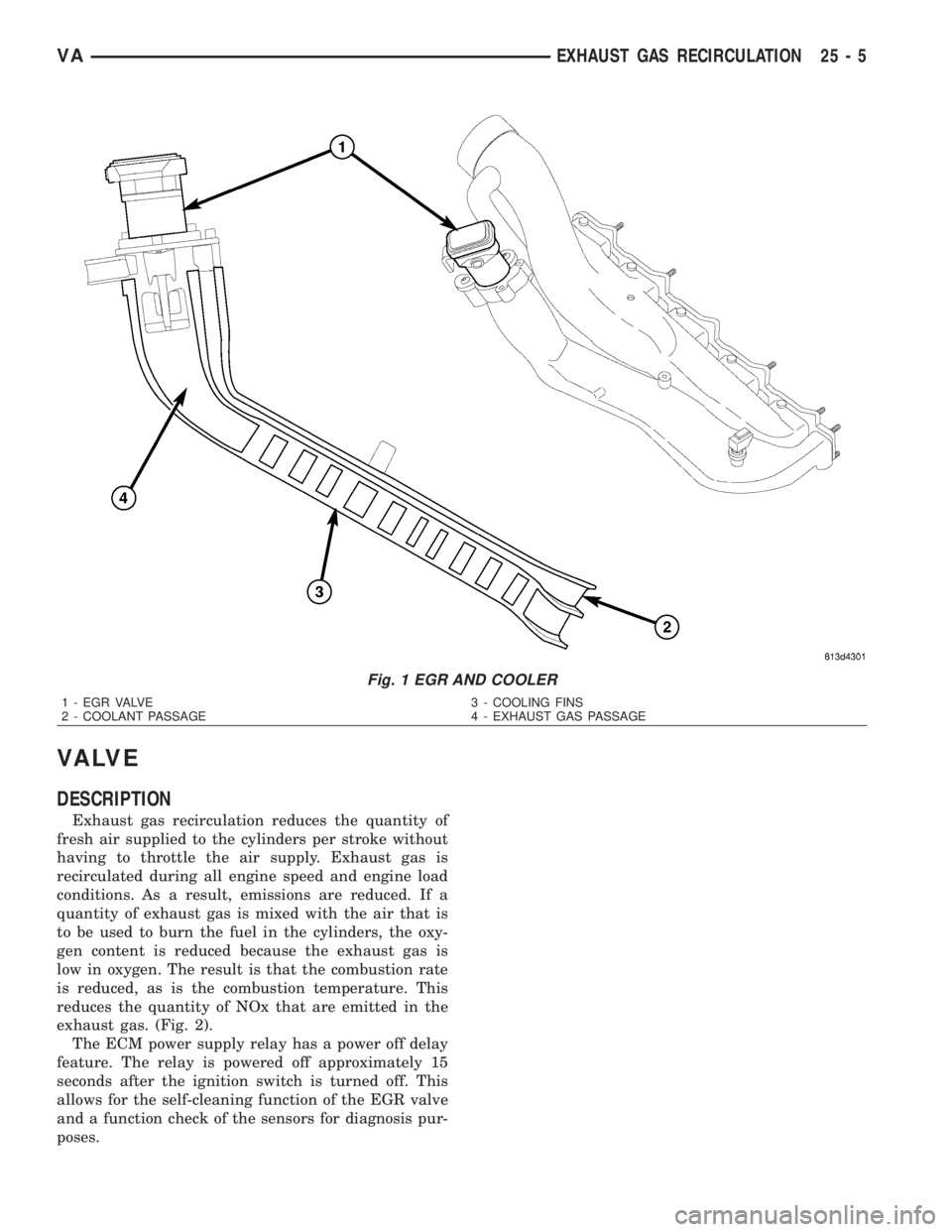
DESCRIPTION
Exhaust gas recirculation reduces the quantity of
fresh air supplied to the cylinders per stroke without
having to throttle the air supply. Exhaust gas is
recirculated during all engine speed and engine load
conditions. As a result, emissions are reduced. If a
quantity of exhaust gas is mixed with the air that is
to be used to burn the fuel in the cylinders, the oxy-
gen content is reduced because the exhaust gas is
low in oxygen. The result is that the combustion rate
is reduced, as is the combustion temperature. This
reduces the quantity of NOx that are emitted in the
exhaust gas. (Fig. 2).
The ECM power supply relay has a power off delay
feature. The relay is powered off approximately 15
seconds after the ignition switch is turned off. This
allows for the self-cleaning function of the EGR valve
and a function check of the sensors for diagnosis pur-
poses.
Fig. 1 EGR AND COOLER
1 - EGR VALVE 3 - COOLING FINS
2 - COOLANT PASSAGE 4 - EXHAUST GAS PASSAGE
VAEXHAUST GAS RECIRCULATION 25 - 5