sensor MERCEDES-BENZ SPRINTER 2006 Service Manual
[x] Cancel search | Manufacturer: MERCEDES-BENZ, Model Year: 2006, Model line: SPRINTER, Model: MERCEDES-BENZ SPRINTER 2006Pages: 2305, PDF Size: 48.12 MB
Page 1745 of 2305
INSPECTION.........................155
ASSEMBLY...........................156
OUTPUT SHAFT BEARING
REMOVAL............................156
INSTALLATION........................158
OUTPUT SHAFT SEAL
REMOVAL............................159
INSTALLATION........................159
PARK LOCK CABLE
REMOVAL............................160
INSTALLATION........................161
PISTONS
DESCRIPTION........................163
OPERATION..........................163
PLANETARY GEARTRAIN
DESCRIPTION........................164
OPERATION..........................165
DISASSEMBLY........................166
ASSEMBLY...........................167
SHIFT MECHANISM
DESCRIPTION........................168
OPERATION..........................168REMOVAL............................169
INSTALLATION........................170
SOLENOID
DESCRIPTION........................171
OPERATION..........................174
TEMPERATURE SENSOR/PARK-NEUTRAL
CONTACT
DESCRIPTION
PARK/NEUTRAL CONTACT.............176
TRANSMISSION TEMPERATURE SENSOR . 176
OPERATION
PARK/NEUTRAL CONTACT.............177
TRANSMISSION TEMPERATURE SENSOR . 177
TORQUE CONVERTER
DESCRIPTION........................178
OPERATION..........................182
REMOVAL............................183
INSTALLATION........................184
TORQUE CONVERTER HUB SEAL
REMOVAL............................184
INSTALLATION........................184
21 - 2 AUTOMATIC TRANSMISSION NAG1 - SERVICE INFORMATIONVA
Page 1785 of 2305
CONDITION POSSIBLE CAUSES CORRECTION
NO UPSHIFT OF 1ST
GEAR AT TIMES1. Connector Ballast Unit. Output
Speed Sensor Loose, Incorrectly
Contacted.1. Check Connectors, Replace
Output Speed sensor If Neces-
sary.
2. Output Speed Sensor Defective 2. Replace Output Speed Sen-
sor.
LEAKAGE AT THE AREA
OF THE ELECTRICAL
PLUG TO THE CONDUC-
TOR PLATE1. Deformation O-Rings. 1. Replace O-Rings.
2. Deformation Adapter. 2.Replace Adaptor.
3. The Conductor Plate Is Not Fitted
Surface To Surface On The Valve
Body In One Corner, The Plug Is
Not Centered In The Socket And
The O-ring Will Not Seal.3. Remove Nose Of Conductor
Plate.
4. Contacting At The Conductor
Plate Leaky. Oil In Harness, Some-
times In The Control Module.4. Replace Conductor Plate.
LEAKAGE AT THE AREA
OF BELL HOUSING/
TORQUE CONVERTER1. Bolts (Torx M6) Outer Disc Carri-
er B1.1. Clean Thread and Install the
Bolts Using Sealer.
OIL LEAKS 1. 6 Lower Bolts (TorxM8) Converter
Housing.1. Clean Thread and Install the
Bolts Using Sealer.
2. Oil Drain Plug Converter Loose
Resp. No Seal Ring Installed.2. Install Drain Plug Correctly.
3. Weld Seam Of Torque Converter
Leaky.3. Replace Torque Converter.
4. Radial Sealing Ring Oil Pump
Defective.4. Replace Sealing Ring.
5. O-Ring Oil Pump Defective Or
Not Installed.5. Install O-Ring.
6. Bushing Of Oil Pump Loose,
caused By Missing Fit Bolt At
Transmission/Engine Flange.6. Install Fit Bolt If Necessary.
STANDARD PROCEDURE - ALUMINUM
THREAD REPAIR
Damaged or worn threads in the aluminum trans-
mission case and valve body can be repaired by the
use of Heli-CoilsŸ, or equivalent. This repair con-
sists of drilling out the worn-out damaged threads.
Then tap the hole with a special Heli-CoilŸ tap, or
equivalent, and installing a Heli-CoilŸ insert, or
equivalent, into the hole. This brings the hole back to
its original thread size.
Heli-CoilŸ, or equivalent, tools and inserts are
readily available from most automotive parts suppli-
ers.
REMOVAL
(1) Disconnect the negative (ground) battery cable.
CAUTION: Isolate ground lead to prevent accidental
contact.(2) Apply parking brake.
(3) Move gear selector lever to position ªNº.
(4) Remove oil drain plug (2) (Fig. 26) and drain
automatic transmission oil into a clean container.
21 - 42 AUTOMATIC TRANSMISSION NAG1 - SERVICE INFORMATIONVA
Page 1848 of 2305
(0.114 in.), 3.2 mm (0.126 in.), and 3.5 mm (0.138
in.).
ELECTROHYDRAULIC UNIT
DESCRIPTION
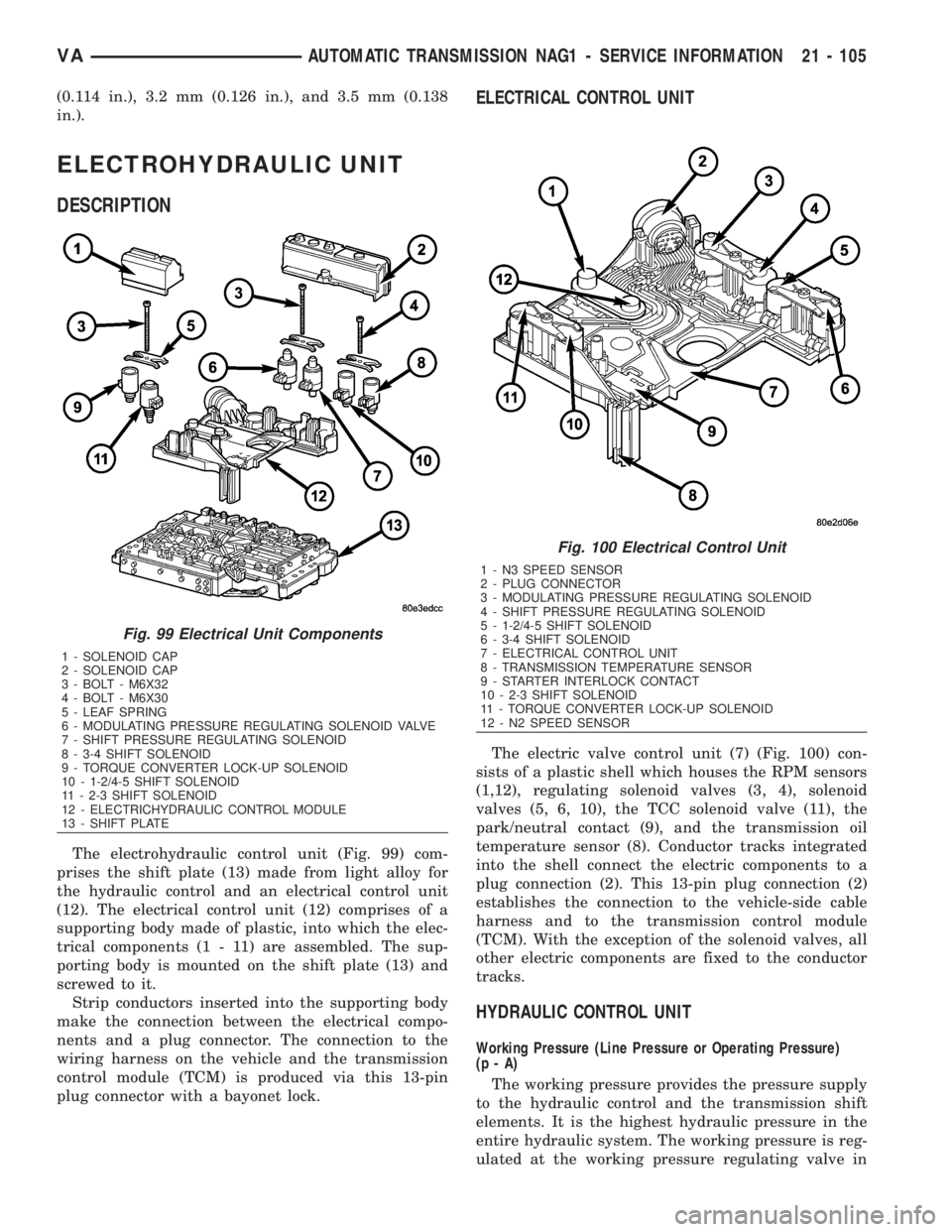
The electrohydraulic control unit (Fig. 99) com-
prises the shift plate (13) made from light alloy for
the hydraulic control and an electrical control unit
(12). The electrical control unit (12) comprises of a
supporting body made of plastic, into which the elec-
trical components (1 - 11) are assembled. The sup-
porting body is mounted on the shift plate (13) and
screwed to it.
Strip conductors inserted into the supporting body
make the connection between the electrical compo-
nents and a plug connector. The connection to the
wiring harness on the vehicle and the transmission
control module (TCM) is produced via this 13-pin
plug connector with a bayonet lock.
ELECTRICAL CONTROL UNIT
The electric valve control unit (7) (Fig. 100) con-
sists of a plastic shell which houses the RPM sensors
(1,12), regulating solenoid valves (3, 4), solenoid
valves (5, 6, 10), the TCC solenoid valve (11), the
park/neutral contact (9), and the transmission oil
temperature sensor (8). Conductor tracks integrated
into the shell connect the electric components to a
plug connection (2). This 13-pin plug connection (2)
establishes the connection to the vehicle-side cable
harness and to the transmission control module
(TCM). With the exception of the solenoid valves, all
other electric components are fixed to the conductor
tracks.
HYDRAULIC CONTROL UNIT
Working Pressure (Line Pressure or Operating Pressure)
(p-A)
The working pressure provides the pressure supply
to the hydraulic control and the transmission shift
elements. It is the highest hydraulic pressure in the
entire hydraulic system. The working pressure is reg-
ulated at the working pressure regulating valve in
Fig. 99 Electrical Unit Components
1 - SOLENOID CAP
2 - SOLENOID CAP
3 - BOLT - M6X32
4 - BOLT - M6X30
5 - LEAF SPRING
6 - MODULATING PRESSURE REGULATING SOLENOID VALVE
7 - SHIFT PRESSURE REGULATING SOLENOID
8 - 3-4 SHIFT SOLENOID
9 - TORQUE CONVERTER LOCK-UP SOLENOID
10 - 1-2/4-5 SHIFT SOLENOID
11 - 2-3 SHIFT SOLENOID
12 - ELECTRICHYDRAULIC CONTROL MODULE
13 - SHIFT PLATE
Fig. 100 Electrical Control Unit
1 - N3 SPEED SENSOR
2 - PLUG CONNECTOR
3 - MODULATING PRESSURE REGULATING SOLENOID
4 - SHIFT PRESSURE REGULATING SOLENOID
5 - 1-2/4-5 SHIFT SOLENOID
6 - 3-4 SHIFT SOLENOID
7 - ELECTRICAL CONTROL UNIT
8 - TRANSMISSION TEMPERATURE SENSOR
9 - STARTER INTERLOCK CONTACT
10 - 2-3 SHIFT SOLENOID
11 - TORQUE CONVERTER LOCK-UP SOLENOID
12 - N2 SPEED SENSOR
VAAUTOMATIC TRANSMISSION NAG1 - SERVICE INFORMATION 21 - 105
Page 1855 of 2305
Regulating Valve Pressure Regulating Valve
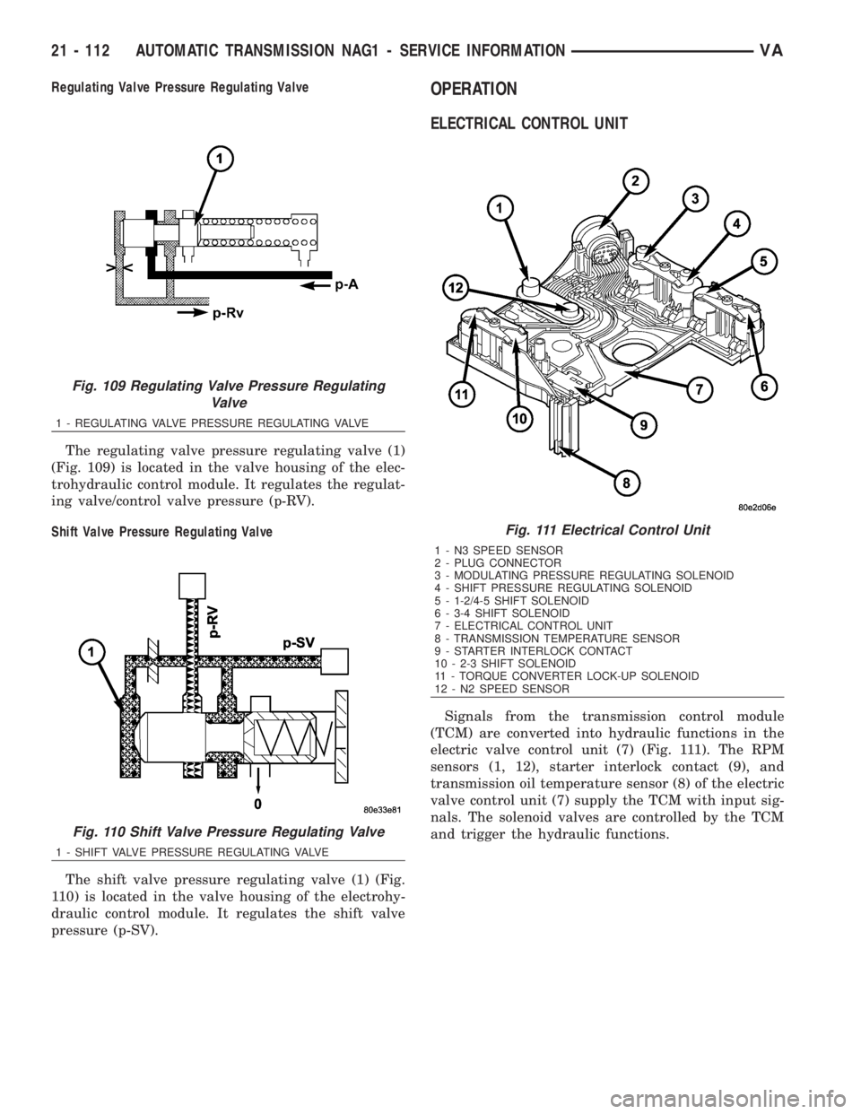
The regulating valve pressure regulating valve (1)
(Fig. 109) is located in the valve housing of the elec-
trohydraulic control module. It regulates the regulat-
ing valve/control valve pressure (p-RV).
Shift Valve Pressure Regulating Valve
The shift valve pressure regulating valve (1) (Fig.
110) is located in the valve housing of the electrohy-
draulic control module. It regulates the shift valve
pressure (p-SV).OPERATION
ELECTRICAL CONTROL UNIT
Signals from the transmission control module
(TCM) are converted into hydraulic functions in the
electric valve control unit (7) (Fig. 111). The RPM
sensors (1, 12), starter interlock contact (9), and
transmission oil temperature sensor (8) of the electric
valve control unit (7) supply the TCM with input sig-
nals. The solenoid valves are controlled by the TCM
and trigger the hydraulic functions.
Fig. 109 Regulating Valve Pressure Regulating
Valve
1 - REGULATING VALVE PRESSURE REGULATING VALVE
Fig. 110 Shift Valve Pressure Regulating Valve
1 - SHIFT VALVE PRESSURE REGULATING VALVE
Fig. 111 Electrical Control Unit
1 - N3 SPEED SENSOR
2 - PLUG CONNECTOR
3 - MODULATING PRESSURE REGULATING SOLENOID
4 - SHIFT PRESSURE REGULATING SOLENOID
5 - 1-2/4-5 SHIFT SOLENOID
6 - 3-4 SHIFT SOLENOID
7 - ELECTRICAL CONTROL UNIT
8 - TRANSMISSION TEMPERATURE SENSOR
9 - STARTER INTERLOCK CONTACT
10 - 2-3 SHIFT SOLENOID
11 - TORQUE CONVERTER LOCK-UP SOLENOID
12 - N2 SPEED SENSOR
21 - 112 AUTOMATIC TRANSMISSION NAG1 - SERVICE INFORMATIONVA
Page 1864 of 2305
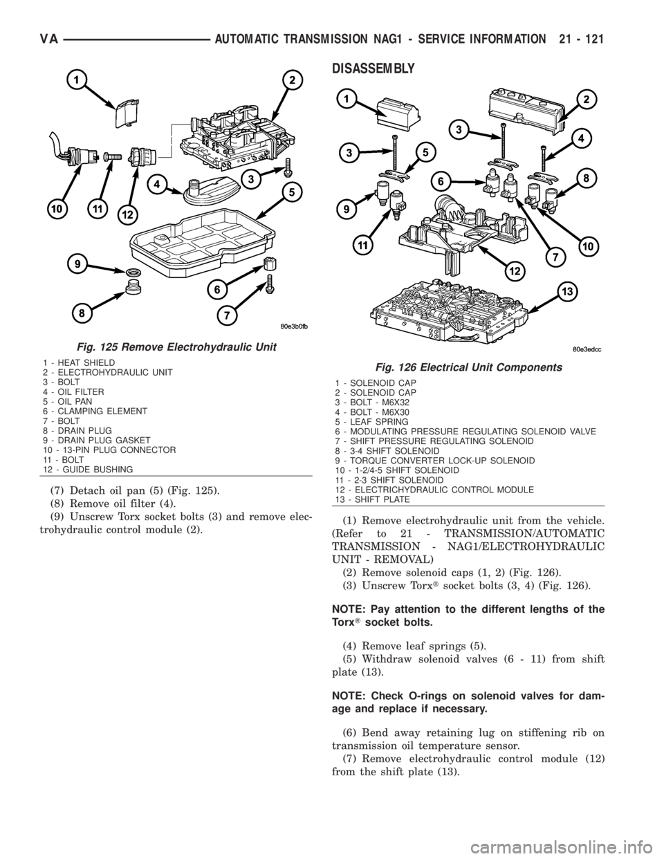
(7) Detach oil pan (5) (Fig. 125).
(8) Remove oil filter (4).
(9) Unscrew Torx socket bolts (3) and remove elec-
trohydraulic control module (2).
DISASSEMBLY
(1) Remove electrohydraulic unit from the vehicle.
(Refer to 21 - TRANSMISSION/AUTOMATIC
TRANSMISSION - NAG1/ELECTROHYDRAULIC
UNIT - REMOVAL)
(2) Remove solenoid caps (1, 2) (Fig. 126).
(3) Unscrew Torxtsocket bolts (3, 4) (Fig. 126).
NOTE: Pay attention to the different lengths of the
TorxTsocket bolts.
(4) Remove leaf springs (5).
(5) Withdraw solenoid valves (6 - 11) from shift
plate (13).
NOTE: Check O-rings on solenoid valves for dam-
age and replace if necessary.
(6) Bend away retaining lug on stiffening rib on
transmission oil temperature sensor.
(7) Remove electrohydraulic control module (12)
from the shift plate (13).
Fig. 125 Remove Electrohydraulic Unit
1 - HEAT SHIELD
2 - ELECTROHYDRAULIC UNIT
3 - BOLT
4 - OIL FILTER
5 - OIL PAN
6 - CLAMPING ELEMENT
7 - BOLT
8 - DRAIN PLUG
9 - DRAIN PLUG GASKET
10 - 13-PIN PLUG CONNECTOR
11 - BOLT
12 - GUIDE BUSHINGFig. 126 Electrical Unit Components
1 - SOLENOID CAP
2 - SOLENOID CAP
3 - BOLT - M6X32
4 - BOLT - M6X30
5 - LEAF SPRING
6 - MODULATING PRESSURE REGULATING SOLENOID VALVE
7 - SHIFT PRESSURE REGULATING SOLENOID
8 - 3-4 SHIFT SOLENOID
9 - TORQUE CONVERTER LOCK-UP SOLENOID
10 - 1-2/4-5 SHIFT SOLENOID
11 - 2-3 SHIFT SOLENOID
12 - ELECTRICHYDRAULIC CONTROL MODULE
13 - SHIFT PLATE
VAAUTOMATIC TRANSMISSION NAG1 - SERVICE INFORMATION 21 - 121
Page 1872 of 2305
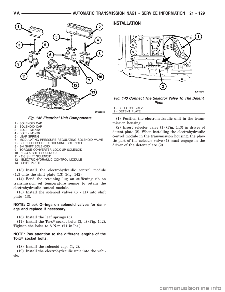
(13) Install the electrohydraulic control module
(12) onto the shift plate (13) (Fig. 142).
(14) Bend the retaining lug on stiffening rib on
transmission oil temperature sensor to retain the
electrohydraulic control module.
(15) Install the solenoid valves (6 - 11) into shift
plate (13).
NOTE: Check O-rings on solenoid valves for dam-
age and replace if necessary.
(16) Install the leaf springs (5).
(17) Install the Torxtsocket bolts (3, 4) (Fig. 142).
Tighten the bolts to 8 N´m (71 in.lbs.).
NOTE: Pay attention to the different lengths of the
TorxTsocket bolts.
(18) Install the solenoid caps (1, 2).
(19) Install the electrohydraulic unit into the vehi-
cle.
INSTALLATION
(1) Position the electrohydraulic unit in the trans-
mission housing.
(2) Insert selector valve (1) (Fig. 143) in driver of
detent plate (2). When installing the electrohydraulic
control module in the transmission housing, the plas-
tic part of the selector valve (1) must engage in the
driver of the detent plate (2).Fig. 142 Electrical Unit Components
1 - SOLENOID CAP
2 - SOLENOID CAP
3 - BOLT - M6X32
4 - BOLT - M6X30
5 - LEAF SPRING
6 - MODULATING PRESSURE REGULATING SOLENOID VALVE
7 - SHIFT PRESSURE REGULATING SOLENOID
8 - 3-4 SHIFT SOLENOID
9 - TORQUE CONVERTER LOCK-UP SOLENOID
10 - 1-2/4-5 SHIFT SOLENOID
11 - 2-3 SHIFT SOLENOID
12 - ELECTRICHYDRAULIC CONTROL MODULE
13 - SHIFT PLATE
Fig. 143 Connect The Selector Valve To The Detent
Plate
1 - SELECTOR VALVE
2 - DETENT PLATE
VAAUTOMATIC TRANSMISSION NAG1 - SERVICE INFORMATION 21 - 129
Page 1876 of 2305
(7) Check transmission oil temperature.
NOTE: The true transmission oil temperature can
only be read by a scan tool in REVERSE or any for-
ward gear position. (Refer to 21 - AUTOMATIC
TRANSMISSION- NAG1/TRANSMISSION TEMPERA-
TURE SENSOR/PARK-NEUTRAL SWITCH - OPERA-
TION)
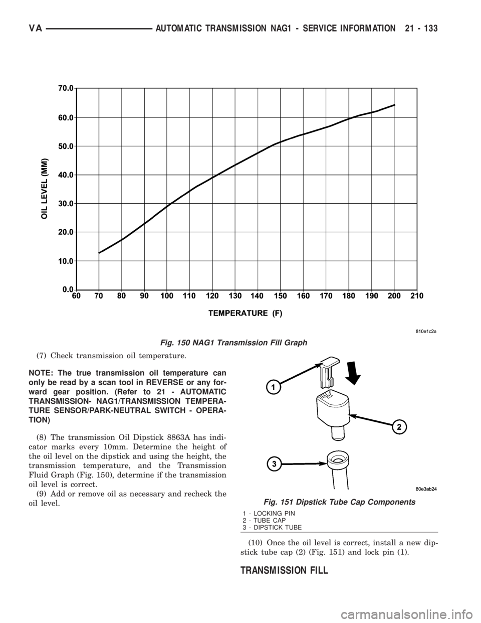
(8) The transmission Oil Dipstick 8863A has indi-
cator marks every 10mm. Determine the height of
the oil level on the dipstick and using the height, the
transmission temperature, and the Transmission
Fluid Graph (Fig. 150), determine if the transmission
oil level is correct.
(9) Add or remove oil as necessary and recheck the
oil level.
(10) Once the oil level is correct, install a new dip-
stick tube cap (2) (Fig. 151) and lock pin (1).
TRANSMISSION FILL
Fig. 150 NAG1 Transmission Fill Graph
Fig. 151 Dipstick Tube Cap Components
1 - LOCKING PIN
2 - TUBE CAP
3 - DIPSTICK TUBE
VAAUTOMATIC TRANSMISSION NAG1 - SERVICE INFORMATION 21 - 133
Page 1896 of 2305
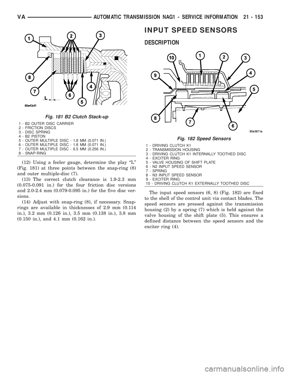
(12) Using a feeler gauge, determine the play ªLº
(Fig. 181) at three points between the snap-ring (8)
and outer multiple-disc (7).
(13) The correct clutch clearance is 1.9-2.3 mm
(0.075-0.091 in.) for the four friction disc versions
and 2.0-2.4 mm (0.079-0.095 in.) for the five disc ver-
sions.
(14) Adjust with snap-ring (8), if necessary. Snap-
rings are available in thicknesses of 2.9 mm (0.114
in.), 3.2 mm (0.126 in.), 3.5 mm (0.138 in.), 3.8 mm
(0.150 in.), and 4.1 mm (0.162 in.).
INPUT SPEED SENSORS
DESCRIPTION
The input speed sensors (6, 8) (Fig. 182) are fixed
to the shell of the control unit via contact blades. The
speed sensors are pressed against the transmission
housing (2) by a spring (7) which is held against the
valve housing of the shift plate (5). This ensures a
defined distance between the speed sensors and the
exciter ring (4).
Fig. 181 B2 Clutch Stack-up
1 - B2 OUTER DISC CARRIER
2 - FRICTION DISCS
3 - DISC SPRING
4 - B2 PISTON
5 - OUTER MULTIPLE DISC - 1.8 MM (0.071 IN.)
6 - OUTER MULTIPLE DISC - 1.8 MM (0.071 IN.)
7 - OUTER MULTIPLE DISC - 6.5 MM (0.256 IN.)
8 - SNAP-RING
Fig. 182 Speed Sensors
1 - DRIVING CLUTCH K1
2 - TRANSMISSION HOUSING
3 - DRIVING CLUTCH K1 INTERNALLY TOOTHED DISC
4 - EXCITER RING
5 - VALVE HOUSING OF SHIFT PLATE
6 - N2 INPUT SPEED SENSOR
7 - SPRING
8 - N3 INPUT SPEED SENSOR
9 - EXCITER RING
10 - DRIVING CLUTCH K1 EXTERNALLY TOOTHED DISC
VAAUTOMATIC TRANSMISSION NAG1 - SERVICE INFORMATION 21 - 153
Page 1897 of 2305
OPERATION
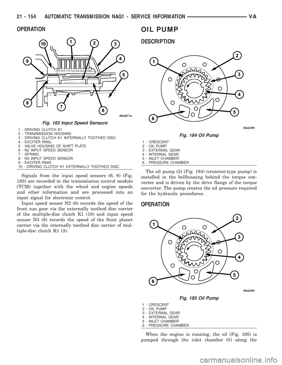
Signals from the input speed sensors (6, 8) (Fig.
183) are recorded in the transmission control module
(TCM) together with the wheel and engine speeds
and other information and are processed into an
input signal for electronic control.
Input speed sensor N2 (6) records the speed of the
front sun gear via the externally toothed disc carrier
of the multiple-disc clutch K1 (10) and input speed
sensor N3 (8) records the speed of the front planet
carrier via the internally toothed disc carrier of mul-
tiple-disc clutch K1 (3).
OIL PUMP
DESCRIPTION
The oil pump (2) (Fig. 184) (crescent-type pump) is
installed in the bellhousing behind the torque con-
verter and is driven by the drive flange of the torque
converter. The pump creates the oil pressure required
for the hydraulic procedures.
OPERATION
When the engine is running, the oil (Fig. 185) is
pumped through the inlet chamber (5) along the
Fig. 183 Input Speed Sensors
1 - DRIVING CLUTCH K1
2 - TRANSMISSION HOUSING
3 - DRIVING CLUTCH K1 INTERNALLY TOOTHED DISC
4 - EXCITER RING
5 - VALVE HOUSING OF SHIFT PLATE
6 - N2 INPUT SPEED SENSOR
7 - SPRING
8 - N3 INPUT SPEED SENSOR
9 - EXCITER RING
10 - DRIVING CLUTCH K1 EXTERNALLY TOOTHED DISC
Fig. 184 Oil Pump
1 - CRESCENT
2 - OIL PUMP
3 - EXTERNAL GEAR
4 - INTERNAL GEAR
5 - INLET CHAMBER
6 - PRESSURE CHAMBER
Fig. 185 Oil Pump
1 - CRESCENT
2 - OIL PUMP
3 - EXTERNAL GEAR
4 - INTERNAL GEAR
5 - INLET CHAMBER
6 - PRESSURE CHAMBER
21 - 154 AUTOMATIC TRANSMISSION NAG1 - SERVICE INFORMATIONVA
Page 1919 of 2305
SHIFT PRESSURE CONTROL SOLENOID VALVE
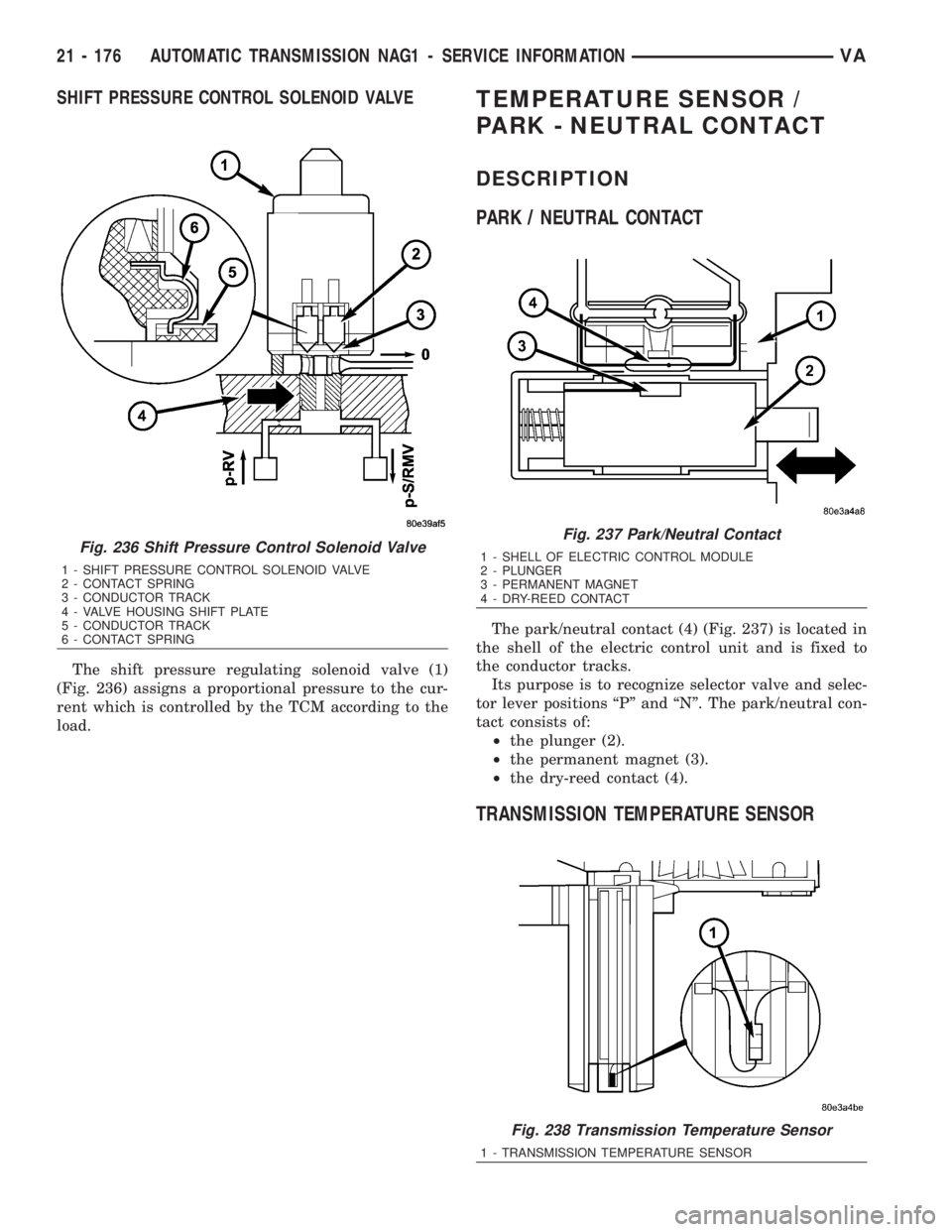
The shift pressure regulating solenoid valve (1)
(Fig. 236) assigns a proportional pressure to the cur-
rent which is controlled by the TCM according to the
load.
TEMPERATURE SENSOR /
PARK - NEUTRAL CONTACT
DESCRIPTION
PARK / NEUTRAL CONTACT
The park/neutral contact (4) (Fig. 237) is located in
the shell of the electric control unit and is fixed to
the conductor tracks.
Its purpose is to recognize selector valve and selec-
tor lever positions ªPº and ªNº. The park/neutral con-
tact consists of:
²the plunger (2).
²the permanent magnet (3).
²the dry-reed contact (4).
TRANSMISSION TEMPERATURE SENSOR
Fig. 236 Shift Pressure Control Solenoid Valve
1 - SHIFT PRESSURE CONTROL SOLENOID VALVE
2 - CONTACT SPRING
3 - CONDUCTOR TRACK
4 - VALVE HOUSING SHIFT PLATE
5 - CONDUCTOR TRACK
6 - CONTACT SPRING
Fig. 237 Park/Neutral Contact
1 - SHELL OF ELECTRIC CONTROL MODULE
2 - PLUNGER
3 - PERMANENT MAGNET
4 - DRY-REED CONTACT
Fig. 238 Transmission Temperature Sensor
1 - TRANSMISSION TEMPERATURE SENSOR
21 - 176 AUTOMATIC TRANSMISSION NAG1 - SERVICE INFORMATIONVA