Condenser MERCEDES-BENZ SPRINTER 2006 Service Manual
[x] Cancel search | Manufacturer: MERCEDES-BENZ, Model Year: 2006, Model line: SPRINTER, Model: MERCEDES-BENZ SPRINTER 2006Pages: 2305, PDF Size: 48.12 MB
Page 830 of 2305
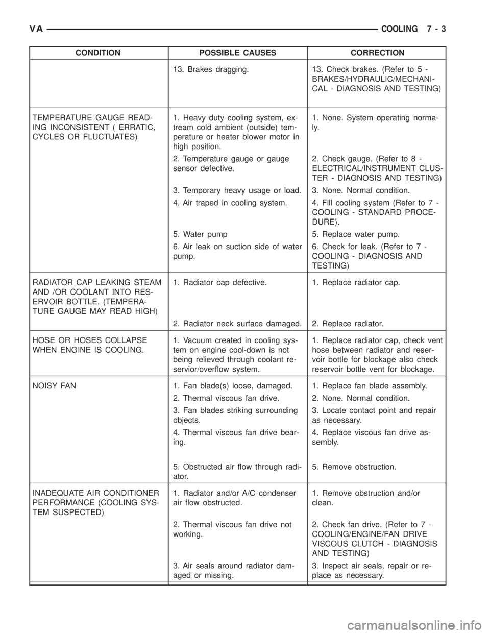
CONDITION POSSIBLE CAUSES CORRECTION
13. Brakes dragging. 13. Check brakes. (Refer to 5 -
BRAKES/HYDRAULIC/MECHANI-
CAL - DIAGNOSIS AND TESTING)
TEMPERATURE GAUGE READ-
ING INCONSISTENT ( ERRATIC,
CYCLES OR FLUCTUATES)1. Heavy duty cooling system, ex-
tream cold ambient (outside) tem-
perature or heater blower motor in
high position.1. None. System operating norma-
ly.
2. Temperature gauge or gauge
sensor defective.2. Check gauge. (Refer to 8 -
ELECTRICAL/INSTRUMENT CLUS-
TER - DIAGNOSIS AND TESTING)
3. Temporary heavy usage or load. 3. None. Normal condition.
4. Air traped in cooling system. 4. Fill cooling system (Refer to 7 -
COOLING - STANDARD PROCE-
DURE).
5. Water pump 5. Replace water pump.
6. Air leak on suction side of water
pump.6. Check for leak. (Refer to 7 -
COOLING - DIAGNOSIS AND
TESTING)
RADIATOR CAP LEAKING STEAM
AND /OR COOLANT INTO RES-
ERVOIR BOTTLE. (TEMPERA-
TURE GAUGE MAY READ HIGH)1. Radiator cap defective. 1. Replace radiator cap.
2. Radiator neck surface damaged. 2. Replace radiator.
HOSE OR HOSES COLLAPSE
WHEN ENGINE IS COOLING.1. Vacuum created in cooling sys-
tem on engine cool-down is not
being relieved through coolant re-
servior/overflow system.1. Replace radiator cap, check vent
hose between radiator and reser-
voir bottle for blockage also check
reservoir bottle vent for blockage.
NOISY FAN 1. Fan blade(s) loose, damaged. 1. Replace fan blade assembly.
2. Thermal viscous fan drive. 2. None. Normal condition.
3. Fan blades striking surrounding
objects.3. Locate contact point and repair
as necessary.
4. Thermal viscous fan drive bear-
ing.4. Replace viscous fan drive as-
sembly.
5. Obstructed air flow through radi-
ator.5. Remove obstruction.
INADEQUATE AIR CONDITIONER
PERFORMANCE (COOLING SYS-
TEM SUSPECTED)1. Radiator and/or A/C condenser
air flow obstructed.1. Remove obstruction and/or
clean.
2. Thermal viscous fan drive not
working.2. Check fan drive. (Refer to 7 -
COOLING/ENGINE/FAN DRIVE
VISCOUS CLUTCH - DIAGNOSIS
AND TESTING)
3. Air seals around radiator dam-
aged or missing.3. Inspect air seals, repair or re-
place as necessary.
VACOOLING 7 - 3
Page 845 of 2305
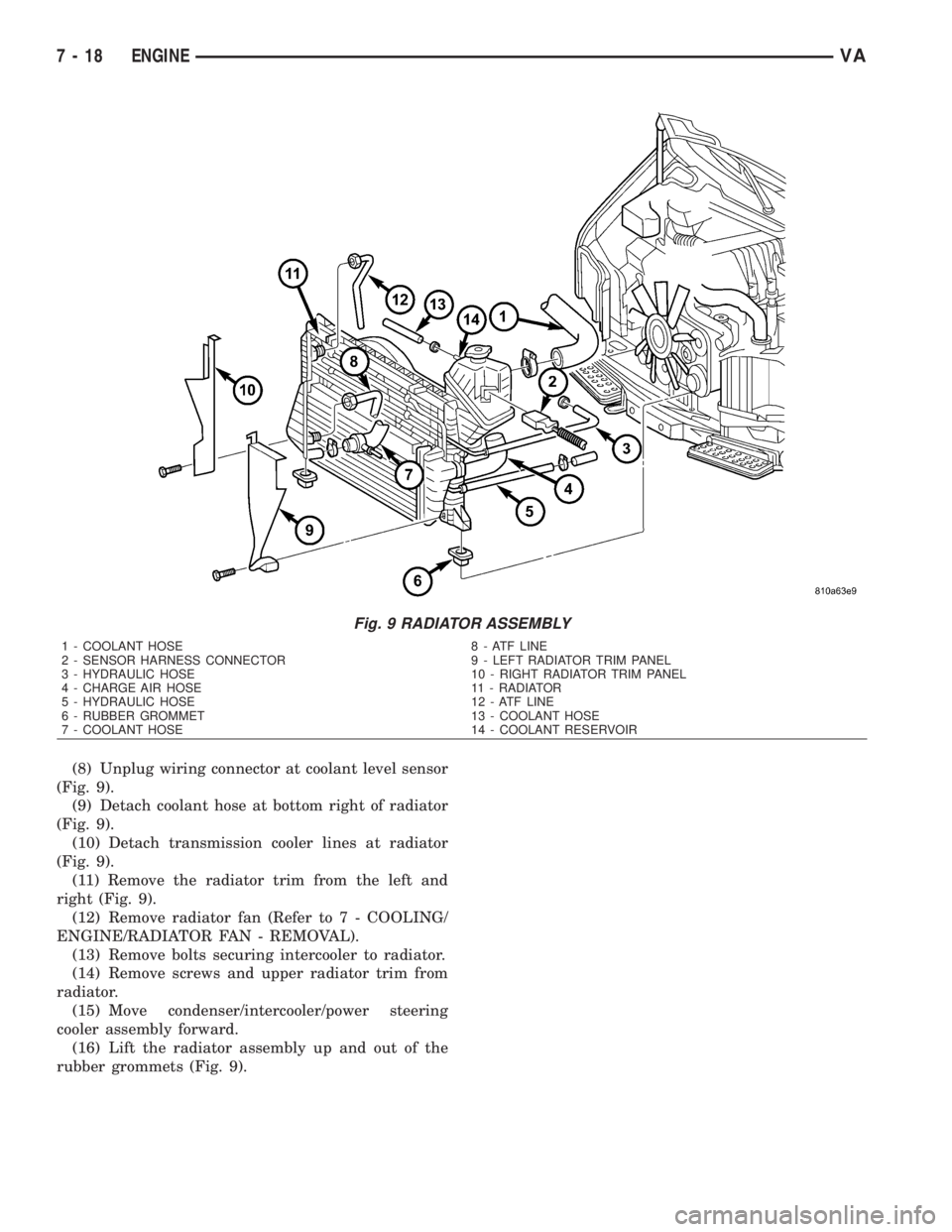
(8) Unplug wiring connector at coolant level sensor
(Fig. 9).
(9) Detach coolant hose at bottom right of radiator
(Fig. 9).
(10) Detach transmission cooler lines at radiator
(Fig. 9).
(11) Remove the radiator trim from the left and
right (Fig. 9).
(12) Remove radiator fan (Refer to 7 - COOLING/
ENGINE/RADIATOR FAN - REMOVAL).
(13) Remove bolts securing intercooler to radiator.
(14) Remove screws and upper radiator trim from
radiator.
(15) Move condenser/intercooler/power steering
cooler assembly forward.
(16) Lift the radiator assembly up and out of the
rubber grommets (Fig. 9).
Fig. 9 RADIATOR ASSEMBLY
1 - COOLANT HOSE 8 - ATF LINE
2 - SENSOR HARNESS CONNECTOR 9 - LEFT RADIATOR TRIM PANEL
3 - HYDRAULIC HOSE 10 - RIGHT RADIATOR TRIM PANEL
4 - CHARGE AIR HOSE 11 - RADIATOR
5 - HYDRAULIC HOSE 12 - ATF LINE
6 - RUBBER GROMMET 13 - COOLANT HOSE
7 - COOLANT HOSE 14 - COOLANT RESERVOIR
7 - 18 ENGINEVA
Page 846 of 2305
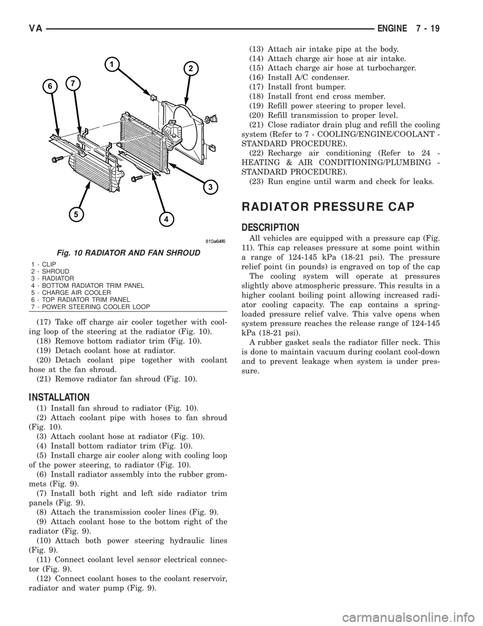
(17) Take off charge air cooler together with cool-
ing loop of the steering at the radiator (Fig. 10).
(18) Remove bottom radiator trim (Fig. 10).
(19) Detach coolant hose at radiator.
(20) Detach coolant pipe together with coolant
hose at the fan shroud.
(21) Remove radiator fan shroud (Fig. 10).
INSTALLATION
(1) Install fan shroud to radiator (Fig. 10).
(2) Attach coolant pipe with hoses to fan shroud
(Fig. 10).
(3) Attach coolant hose at radiator (Fig. 10).
(4) Install bottom radiator trim (Fig. 10).
(5) Install charge air cooler along with cooling loop
of the power steering, to radiator (Fig. 10).
(6) Install radiator assembly into the rubber grom-
mets (Fig. 9).
(7) Install both right and left side radiator trim
panels (Fig. 9).
(8) Attach the transmission cooler lines (Fig. 9).
(9) Attach coolant hose to the bottom right of the
radiator (Fig. 9).
(10) Attach both power steering hydraulic lines
(Fig. 9).
(11) Connect coolant level sensor electrical connec-
tor (Fig. 9).
(12) Connect coolant hoses to the coolant reservoir,
radiator and water pump (Fig. 9).(13) Attach air intake pipe at the body.
(14) Attach charge air hose at air intake.
(15) Attach charge air hose at turbocharger.
(16) Install A/C condenser.
(17) Install front bumper.
(18) Install front end cross member.
(19) Refill power steering to proper level.
(20) Refill transmission to proper level.
(21) Close radiator drain plug and refill the cooling
system (Refer to 7 - COOLING/ENGINE/COOLANT -
STANDARD PROCEDURE).
(22) Recharge air conditioning (Refer to 24 -
HEATING & AIR CONDITIONING/PLUMBING -
STANDARD PROCEDURE).
(23) Run engine until warm and check for leaks.
RADIATOR PRESSURE CAP
DESCRIPTION
All vehicles are equipped with a pressure cap (Fig.
11). This cap releases pressure at some point within
a range of 124-145 kPa (18-21 psi). The pressure
relief point (in pounds) is engraved on top of the cap
The cooling system will operate at pressures
slightly above atmospheric pressure. This results in a
higher coolant boiling point allowing increased radi-
ator cooling capacity. The cap contains a spring-
loaded pressure relief valve. This valve opens when
system pressure reaches the release range of 124-145
kPa (18-21 psi).
A rubber gasket seals the radiator filler neck. This
is done to maintain vacuum during coolant cool-down
and to prevent leakage when system is under pres-
sure.
Fig. 10 RADIATOR AND FAN SHROUD
1 - CLIP
2 - SHROUD
3 - RADIATOR
4 - BOTTOM RADIATOR TRIM PANEL
5 - CHARGE AIR COOLER
6 - TOP RADIATOR TRIM PANEL
7 - POWER STEERING COOLER LOOP
VAENGINE 7 - 19
Page 1581 of 2305
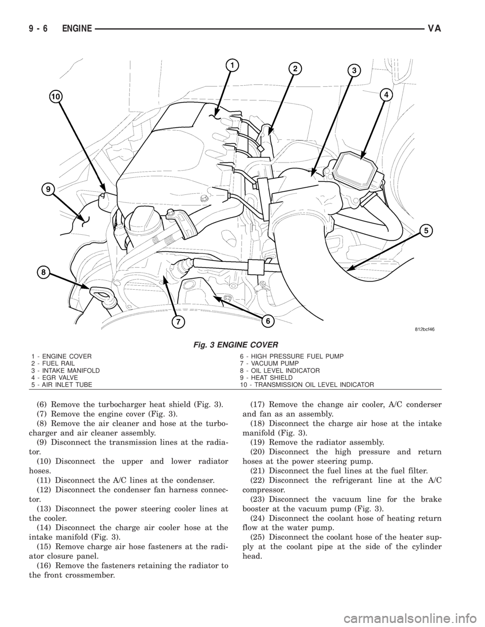
(6) Remove the turbocharger heat shield (Fig. 3).
(7) Remove the engine cover (Fig. 3).
(8) Remove the air cleaner and hose at the turbo-
charger and air cleaner assembly.
(9) Disconnect the transmission lines at the radia-
tor.
(10) Disconnect the upper and lower radiator
hoses.
(11) Disconnect the A/C lines at the condenser.
(12) Disconnect the condenser fan harness connec-
tor.
(13) Disconnect the power steering cooler lines at
the cooler.
(14) Disconnect the charge air cooler hose at the
intake manifold (Fig. 3).
(15) Remove charge air hose fasteners at the radi-
ator closure panel.
(16) Remove the fasteners retaining the radiator to
the front crossmember.(17) Remove the change air cooler, A/C conderser
and fan as an assembly.
(18) Disconnect the charge air hose at the intake
manifold (Fig. 3).
(19) Remove the radiator assembly.
(20) Disconnect the high pressure and return
hoses at the power steering pump.
(21) Disconnect the fuel lines at the fuel filter.
(22) Disconnect the refrigerant line at the A/C
compressor.
(23) Disconnect the vacuum line for the brake
booster at the vacuum pump (Fig. 3).
(24) Disconnect the coolant hose of heating return
flow at the water pump.
(25) Disconnect the coolant hose of the heater sup-
ply at the coolant pipe at the side of the cylinder
head.
Fig. 3 ENGINE COVER
1 - ENGINE COVER 6 - HIGH PRESSURE FUEL PUMP
2 - FUEL RAIL 7 - VACUUM PUMP
3 - INTAKE MANIFOLD 8 - OIL LEVEL INDICATOR
4 - EGR VALVE 9 - HEAT SHIELD
5 - AIR INLET TUBE 10 - TRANSMISSION OIL LEVEL INDICATOR
9 - 6 ENGINEVA
Page 1585 of 2305
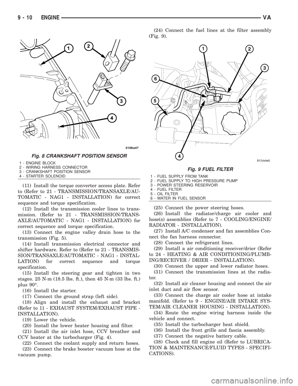
(11) Install the torque converter access plate. Refer
to (Refer to 21 - TRANSMISSION/TRANSAXLE/AU-
TOMATIC - NAG1 - INSTALLATION) for correct
sequence and torque specification.
(12) Install the transmission cooler lines to trans-
mission. (Refer to 21 - TRANSMISSION/TRANS-
AXLE/AUTOMATIC - NAG1 - INSTALLATION) for
correct sequence and torque specification.
(13) Connect the engine valley drain hose to the
transmission (Fig. 5).
(14) Install transmission electrical connector and
shifter hardware. Refer to (Refer to 21 - TRANSMIS-
SION/TRANSAXLE/AUTOMATIC - NAG1 - INSTAL-
LATION) for correct sequence and torque
specification.
(15) Install the steering gear and tighten in two
stages. 25 N´m (18.5 lbs. ft.), then 45 N´m (33 lbs. ft.)
plus 90É.
(16) Install the starter.
(17) Connect the ground strap (left side).
(18) Align and install the exhaust and bracket
(Refer to 11 - EXHAUST SYSTEM/EXHAUST PIPE -
INSTALLATION).
(19) Lower the vehicle.
(20) Install the lower heater housing and filter.
(21) Install the air inlet hose, CCV breather and
CCV heater at the turbocharger (Fig. 4).
(22) Connect the coolant supply and return hoses.
(23) Connect the brake booster vacuum hose at the
vacuum pump.(24) Connect the fuel lines at the filter assembly
(Fig. 9).
(25) Connect the power steering hoses.
(26) Install the radiator/charge air cooler and
hose(s) assemblies (Refer to 7 - COOLING/ENGINE/
RADIATOR - INSTALLATION).
(27) Install A/C condenser and fan assemblies Con-
nect the fan harness connector.
(28) Connect the refrigerant lines.
(29) Install a air conditioning receiver/drier (Refer
to 24 - HEATING & AIR CONDITIONING/PLUMB-
ING/RECEIVER / DRIER - INSTALLATION).
(30) Connect the upper and lower radiator hoses.
(31) Connect the transmission lines at the radia-
tor.
(32) Install air cleaner housing and connect the air
inlet duct and air flow sensor.
(33) Connect the charge air cooler hose at intake
manifold. (Refer to 9 - ENGINE/AIR INTAKE SYS-
TEM/AIR CLEANER HOUSING - INSTALLATION).
(34) Route the engine wiring harness inside the
vehicle and connect.
(35) Install the turbocharger heat shield.
(36) Install the front grille and fascia assembly.
(37) Connect the negative battery cable.
(38) Check and fill engine oil (Refer to LUBRICA-
TION & MAINTENANCE/FLUID TYPES - SPECIFI-
CATIONS).
Fig. 8 CRANKSHAFT POSITION SENSOR
1 - ENGINE BLOCK
2 - WIRING HARNESS CONNECTOR
3 - CRANKSHAFT POSITION SENSOR
4 - STARTER SOLENOID
Fig. 9 FUEL FILTER
1 - FUEL SUPPLY FROM TANK
2 - FUEL SUPPLY TO HIGH PRESSURE PUMP
3 - POWER STEERING RESERVOIR
4 - FUEL FILTER
5 - OIL FILTER
6 - WATER IN FUEL SENSOR
9 - 10 ENGINEVA
Page 1742 of 2305
SPECIFICATIONS - TORQUE CHART
TORQUE SPECIFICATIONS
DESCRIPTION N´m Ft. Lbs. In. Lbs.
Power Steering Pump To
Timing Case Cover/Sup-
port21 15 185
High Pressure Flexible
Hose To Power Steering
Pump38 28 336
Power Steering Pulley To
Pump30 22 265
FLUID
STANDARD PROCEDURE
POWER STEERING PUMP FILL AND BLEED
PROCEDURE
(1) Remove the cap from the fluid reservoir.
Check cap seal for damage and replace if
needed.
(2) Fill the power steering pump with approved
fluid (Refer to LUBRICATION & MAINTENANCE/
FLUID TYPES - DESCRIPTION).Do not fill fluid
beyond the MAX mark.
(3) Raise the vehicles front wheels off the ground.
(4) With the engine off turn the steering wheel
from right to left.Perform this step until all the
bubble formations can no longer be seen in the
power steering reservoir.
(5) Start the engine and turn the steering wheel
with the engine at idle speed then shut the engine off
and check for correct oil level and no bubble in the
system.
(6) Reinstall power steering cap tightly.
(7) Test the system for leaks and proper operation.
FLUID COOLER TUBE
REMOVAL
(1) Siphon as much power steering fluid as possi-
ble out of the reservoir.
(2) Remove the grille (Refer to 23 - BODY/EXTE-
RIOR/GRILLE - REMOVAL).
(3) Remove the left headlight assembly.
(4) Disconnect the return lines from the cooler
tube.
(5) Remove the radiator clips (2).
(6) Remove the heat shield bolt for the turbo at
the core support.
(7) Remove the right headlight assembly.(8) Remove the core support bolts (4) and discon-
nect the hood latch cable.
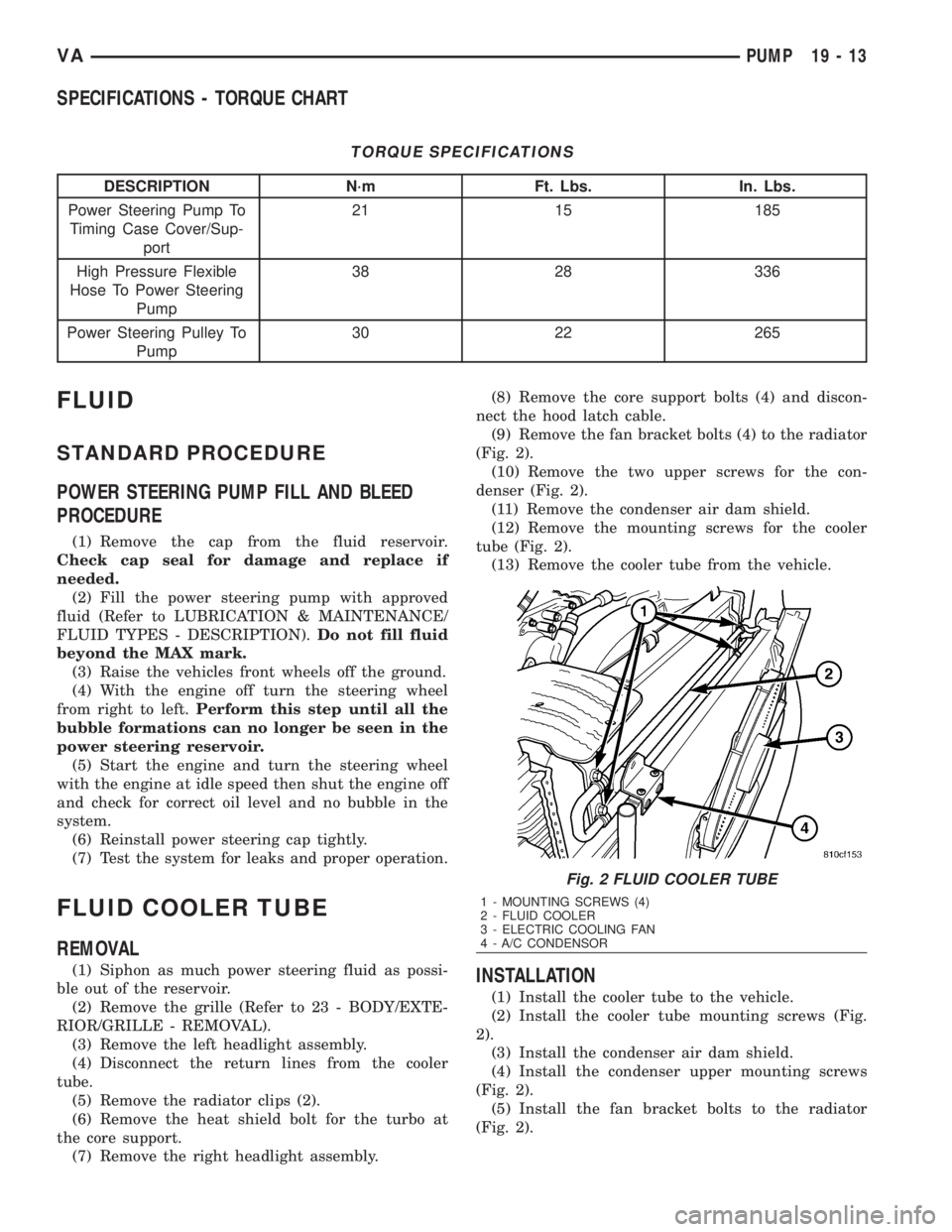
(9) Remove the fan bracket bolts (4) to the radiator
(Fig. 2).
(10) Remove the two upper screws for the con-
denser (Fig. 2).
(11) Remove the condenser air dam shield.
(12) Remove the mounting screws for the cooler
tube (Fig. 2).
(13) Remove the cooler tube from the vehicle.INSTALLATION
(1) Install the cooler tube to the vehicle.
(2) Install the cooler tube mounting screws (Fig.
2).
(3) Install the condenser air dam shield.
(4) Install the condenser upper mounting screws
(Fig. 2).
(5) Install the fan bracket bolts to the radiator
(Fig. 2).
Fig. 2 FLUID COOLER TUBE
1 - MOUNTING SCREWS (4)
2 - FLUID COOLER
3 - ELECTRIC COOLING FAN
4 - A/C CONDENSOR
VAPUMP 19 - 13
Page 2038 of 2305
HEATING & AIR CONDITIONING
TABLE OF CONTENTS
page page
HEATING & AIR CONDITIONING
DESCRIPTION..........................1
OPERATION............................2
DIAGNOSIS AND TESTING
A/C PERFORMANCE....................3
HEATER PERFORMANCE TEST...........5
ATC FUNCTION TEST...................6
SPECIFICATIONS
HEATING-A/C SYSTEM..................6CONTROLS-FRONT........................8
CONTROLS - REAR......................24
DISTRIBUTION - FRONT...................45
DISTRIBUTION - REAR....................52
PLUMBING.............................60
CABIN HEATER.........................104
HEATING & AIR CONDITION-
ING
DESCRIPTION
An automatic temperature control (ATC) single
zone type heating-A/C system is standard equipment
on this model.
To maintain the performance level of the heating,
ventilation and air conditioning (HVAC) system, the
engine cooling system must be properly maintained.
The use of a bug screen is not recommended. Any
obstructions in front of the radiator or A/C condenser
will reduce the performance of the A/C and engine
cooling systems.
The engine cooling system includes the radiator,
thermostat, radiator hoses and the engine coolant
pump. Refer to 7 - Cooling for more information
before opening or attempting any service to the
engine cooling system.
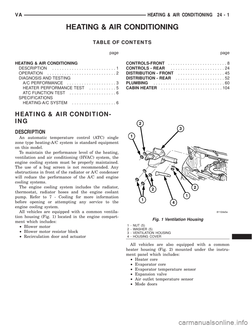
All vehicles are equipped with a common ventila-
tion housing (Fig. 1) located in the engine compart-
ment which includes:
²Blower motor
²Blower motor resistor block
²Recirculation door and actuator
All vehicles are also equipped with a common
heater housing (Fig. 2) mounted under the instru-
ment panel which includes:
²Heater core
²Evaporator core
²Evaporator temperature sensor
²Expansion valve
²Air outlet temperature sensor
²Mode doors
Fig. 1 Ventilation Housing
1 - NUT (5)
2 - WASHER (5)
3 - VENTILATION HOUSING
4 - HOUSING COVER
VAHEATING & AIR CONDITIONING 24 - 1
Page 2042 of 2305
Condition Possible Causes Correction
The low side pressure is
normal or slightly low, and
the high side pressure is too
low.1. Low refrigerant system
charge.1. See Refrigerant System Leaks in this
group. Test the refrigerant system for leaks.
Repair, evacuate and charge the refrigerant
system, if required.
2. Refrigerant flow through the
A/C evaporator is restricted.2. See A/C Evaporator in this group. Replace
the restricted A/C evaporator, if required.
3. Faulty A/C compressor. 3. See A/C Compressor in this group. Re-
place the A/C compressor, if required.
The low side pressure is
normal or slightly high, and
the high side pressure is too
high.1. A/C condenser air flow re-
stricted.1. Check the A/C condenser for damaged
fins, foreign objects obstructing air flow
through the condenser fins, and missing or
improperly installed air seals. Clean, repair, or
replace components as required.
2. Refrigerant flow through the
receiver/drier is restricted.2. See Receiver/Drier in this group. Replace
the restricted receiver/drier, if required.
3. Inoperative radiator cooling
fan.3. Test the radiator cooling fan and replace, if
required. Refer to Group 7 - Cooling.
4. Refrigerant system over-
charged.4. See Refrigerant System Charge in this
group. Recover the refrigerant from the refrig-
erant system. Charge the refrigerant system
to the proper level, if required.
5. Air in the refrigerant system. 5. See Refrigerant System Leaks in this
group. Test the refrigerant system for leaks.
Repair, evacuate and charge the refrigerant
system, if required.
6. Engine overheating. 6. Test the engine cooling system and repair,
if required. Refer to Group 7 - Cooling.
The low side pressure is too
high, and the high side pres-
sure is too low.1. Accessory drive belt slip-
ping.1. Inspect the accessory drive belt condition
and tension. Repair as required. Refer to
Group 7 - Cooling.
2. Faulty A/C expansion valve. 2. See A/C Expansion Valve in this group.
Replace the valve, if required.
3. Faulty A/C compressor. 3. See A/C Compressor in this group. Re-
place the A/C compressor, if required.
The low side pressure is too
low, and the high side pres-
sure is too high.1. Restricted refrigerant flow
through the refrigerant lines.1. See Liquid Line, Suction Line and Dis-
charge Line in this group. Inspect the refriger-
ant lines for kinks, tight bends or improper
routing. Correct the routing or replace the re-
frigerant line, if required.
2. Restricted refrigerant flow
through the A/C expansion
valve.2. See A/C Expansion Valve in this group.
Replace the valve, if required.
3. Restricted refrigerant flow
through the A/C condenser.3. See A/C Condenser in this group. Replace
the restricted A/C condenser, if required.
HEATER PERFORMANCE TEST
Before performing the following tests, perform the
ATC Function Test using the DRBIIItand refer to
Cooling for the procedures to check the radiator cool-
ant level, serpentine drive belt tension, radiator air
flow and the radiator fan operation.
MAXIMUM HEATER OUTPUT
Engine coolant is provided to the heater core
through a heater valve and heater hose. With the
engine idling at normal operating temperature, set
the heater-A/C controls as follows:
²Temperature control in the full hot position
VAHEATING & AIR CONDITIONING 24 - 5
Page 2061 of 2305
CONTROLS - REAR
TABLE OF CONTENTS
page page
A/C CLUTCH RELAY
DESCRIPTION.........................24
OPERATION...........................25
REMOVAL.............................25
INSTALLATION.........................26
A/C CONDENSER FAN RELAY
DESCRIPTION.........................26
OPERATION...........................26
REMOVAL.............................27
INSTALLATION.........................28
A/C CONTROL MODULE
DESCRIPTION.........................28
OPERATION...........................28
REMOVAL.............................29
INSTALLATION.........................30
A/C HIGH PRESSURE SWITCH
DESCRIPTION.........................30
OPERATION...........................30
REMOVAL.............................31
INSTALLATION.........................31
A/C LOW PRESSURE SWITCH
DESCRIPTION.........................32
OPERATION...........................32
REMOVAL.............................32
INSTALLATION.........................33
BLOWER MOTOR RELAY
DESCRIPTION.........................33
OPERATION...........................33
REMOVAL.............................34
INSTALLATION.........................35
BLOWER MOTOR SWITCH
DESCRIPTION.........................35
OPERATION...........................35
DIAGNOSIS AND TESTING
REAR BLOWER MOTOR SWITCH.........36REMOVAL.............................36
INSTALLATION.........................37
EVAPORATOR TEMPERATURE SENSOR
DESCRIPTION.........................37
OPERATION...........................37
REMOVAL.............................37
INSTALLATION.........................38
TEMPERATURE CONTROL
DESCRIPTION.........................38
OPERATION...........................38
DIAGNOSIS AND TESTING
REAR A/C TEMPERATURE CONTROL.....39
REMOVAL.............................39
INSTALLATION.........................40
TEMPERATURE SENSOR
DESCRIPTION.........................40
OPERATION...........................40
DIAGNOSIS AND TESTING
REAR TEMPERATURE SENSOR..........40
REMOVAL.............................40
INSTALLATION.........................41
SUPPRESSOR FILTER - REAR BLOWER
MOTOR
DESCRIPTION.........................41
OPERATION...........................41
REMOVAL.............................42
INSTALLATION.........................43
SUPPRESSOR FILTER - REAR CONDENSER
FA N
DESCRIPTION.........................43
OPERATION...........................44
REMOVAL.............................44
INSTALLATION.........................44
A / C CLUTCH RELAY
DESCRIPTION
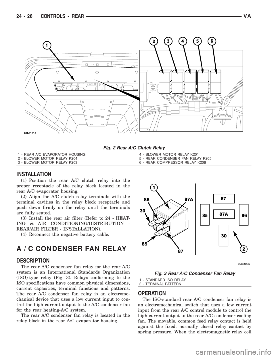
The rear A/C clutch relay for the rear A/C system
is an International Standards Organization (ISO)-
type relay (Fig. 1). Relays conforming to the ISO
specifications have common physical dimensions, cur-
rent capacities, terminal functions and patterns. The
rear A/C clutch relay is an electromechanical device
that uses a low current input controlled by the rear
A/C control module to control the high current output
to the A/C clutch field coil for the rear A/C system.The rear A/C clutch relay is located in the relay
block in the rear A/C evaporator housing.
24 - 24 CONTROLS - REARVA
Page 2063 of 2305
INSTALLATION
(1) Position the rear A/C clutch relay into the
proper receptacle of the relay block located in the
rear A/C evaporator housing.
(2) Align the A/C clutch relay terminals with the
terminal cavities in the relay block receptacle and
push down firmly on the relay until the terminals
are fully seated.
(3) Install the rear air filter (Refer to 24 - HEAT-
ING & AIR CONDITIONING/DISTRIBUTION -
REAR/AIR FILTER - INSTALLATION).
(4) Reconnect the negative battery cable.
A / C CONDENSER FAN RELAY
DESCRIPTION
The rear A/C condenser fan relay for the rear A/C
system is an International Standards Organization
(ISO)-type relay (Fig. 3). Relays conforming to the
ISO specifications have common physical dimensions,
current capacities, terminal functions and patterns.
The rear A/C condenser fan relay is an electrome-
chanical device that uses a low current input to con-
trol the high current output to the A/C condenser fan
for the rear heating-A/C system.
The rear A/C condenser fan relay is located in the
relay block in the rear A/C evaporator housing.
OPERATION
The ISO-standard rear A/C condenser fan relay is
an electromechanical switch that uses a low current
input from the rear A/C control module to control the
high current output to the rear A/C condenser cooling
fan. The movable, common feed relay contact is held
against the fixed, normally closed relay contact by
spring pressure. When the electromagnetic relay coil
Fig. 2 Rear A/C Clutch Relay
1 - REAR A/C EVAPORATOR HOUSING
2 - BLOWER MOTOR RELAY K204
3 - BLOWER MOTOR RELAY K2034 - BLOWER MOTOR RELAY K201
5 - REAR CONDENSER FAN RELAY K205
6 - REAR COMPRESSOR RELAY K206
Fig. 3 Rear A/C Condenser Fan Relay
1 - STANDARD ISO RELAY
2 - TERMINAL PATTERN
24 - 26 CONTROLS - REARVA