fan MERCEDES-BENZ SPRINTER 2006 Service Manual
[x] Cancel search | Manufacturer: MERCEDES-BENZ, Model Year: 2006, Model line: SPRINTER, Model: MERCEDES-BENZ SPRINTER 2006Pages: 2305, PDF Size: 48.12 MB
Page 7 of 2305
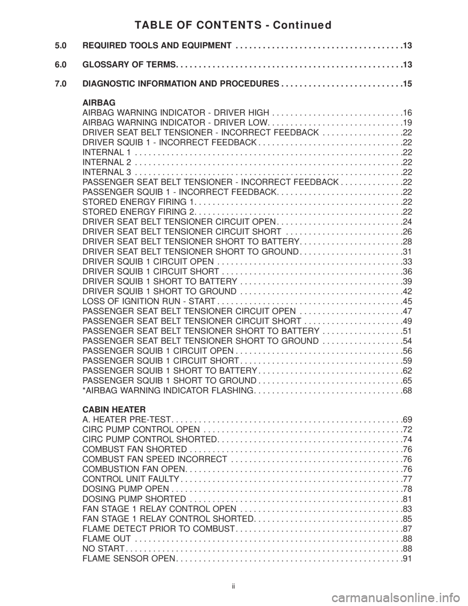
TABLE OF CONTENTS - Continued
5.0 REQUIRED TOOLS AND EQUIPMENT.....................................13
6.0 GLOSSARY OF TERMS..................................................13
7.0 DIAGNOSTIC INFORMATION AND PROCEDURES...........................15
AIRBAG
AIRBAG WARNING INDICATOR - DRIVER HIGH.............................16
AIRBAG WARNING INDICATOR - DRIVER LOW..............................19
DRIVER SEAT BELT TENSIONER - INCORRECT FEEDBACK..................22
DRIVER SQUIB 1 - INCORRECT FEEDBACK................................22
INTERNAL 1...........................................................22
INTERNAL 2...........................................................22
INTERNAL 3...........................................................22
PASSENGER SEAT BELT TENSIONER - INCORRECT FEEDBACK..............22
PASSENGER SQUIB 1 - INCORRECT FEEDBACK............................22
STORED ENERGY FIRING 1..............................................22
STORED ENERGY FIRING 2..............................................22
DRIVER SEAT BELT TENSIONER CIRCUIT OPEN............................24
DRIVER SEAT BELT TENSIONER CIRCUIT SHORT..........................26
DRIVER SEAT BELT TENSIONER SHORT TO BATTERY.......................28
DRIVER SEAT BELT TENSIONER SHORT TO GROUND.......................31
DRIVER SQUIB 1 CIRCUIT OPEN.........................................33
DRIVER SQUIB 1 CIRCUIT SHORT........................................36
DRIVER SQUIB 1 SHORT TO BATTERY....................................39
DRIVER SQUIB 1 SHORT TO GROUND....................................42
LOSS OF IGNITION RUN - START.........................................45
PASSENGER SEAT BELT TENSIONER CIRCUIT OPEN.......................47
PASSENGER SEAT BELT TENSIONER CIRCUIT SHORT......................49
PASSENGER SEAT BELT TENSIONER SHORT TO BATTERY..................51
PASSENGER SEAT BELT TENSIONER SHORT TO GROUND..................54
PASSENGER SQUIB 1 CIRCUIT OPEN.....................................56
PASSENGER SQUIB 1 CIRCUIT SHORT....................................59
PASSENGER SQUIB 1 SHORT TO BATTERY................................62
PASSENGER SQUIB 1 SHORT TO GROUND................................65
*AIRBAG WARNING INDICATOR FLASHING.................................68
CABIN HEATER
A. HEATER PRE-TEST...................................................69
CIRC PUMP CONTROL OPEN............................................72
CIRC PUMP CONTROL SHORTED.........................................74
COMBUST FAN SHORTED...............................................76
COMBUST FAN SPEED INCORRECT......................................76
COMBUSTION FAN OPEN................................................76
CONTROL UNIT FAULTY.................................................77
DOSING PUMP OPEN...................................................78
DOSING PUMP SHORTED...............................................81
FAN STAGE 1 RELAY CONTROL OPEN....................................83
FAN STAGE 1 RELAY CONTROL SHORTED.................................85
FLAME DETECT PRIOR TO COMBUST.....................................87
FLAME OUT...........................................................88
NO START.............................................................88
FLAME SENSOR OPEN..................................................91
ii
Page 8 of 2305
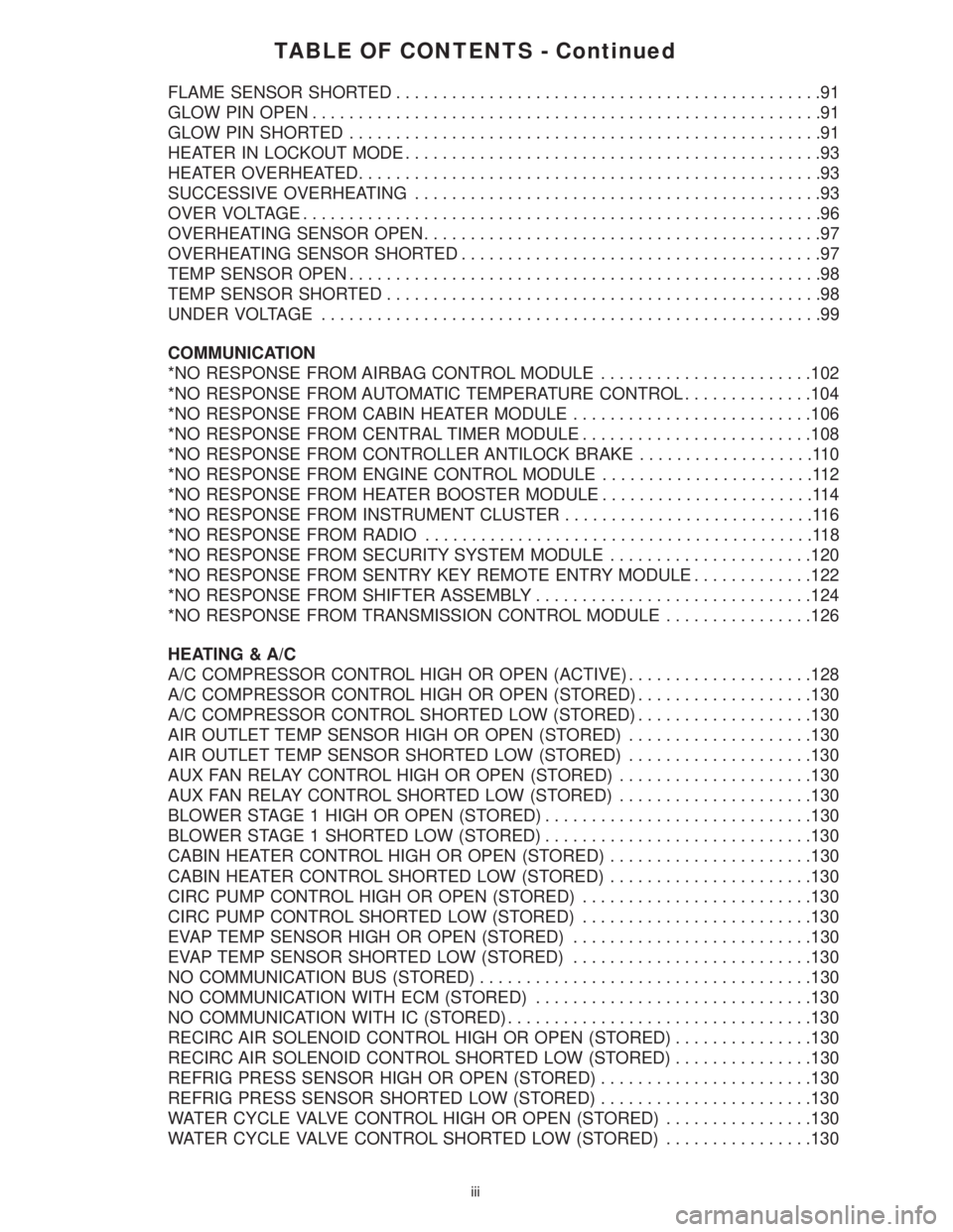
TABLE OF CONTENTS - Continued
FLAME SENSOR SHORTED..............................................91
GLOW PIN OPEN.......................................................91
GLOW PIN SHORTED...................................................91
HEATER IN LOCKOUT MODE.............................................93
HEATER OVERHEATED..................................................93
SUCCESSIVE OVERHEATING............................................93
OVER VOLTAGE........................................................96
OVERHEATING SENSOR OPEN...........................................97
OVERHEATING SENSOR SHORTED.......................................97
TEMP SENSOR OPEN...................................................98
TEMP SENSOR SHORTED...............................................98
UNDER VOLTAGE......................................................99
COMMUNICATION
*NO RESPONSE FROM AIRBAG CONTROL MODULE.......................102
*NO RESPONSE FROM AUTOMATIC TEMPERATURE CONTROL..............104
*NO RESPONSE FROM CABIN HEATER MODULE..........................106
*NO RESPONSE FROM CENTRAL TIMER MODULE.........................108
*NO RESPONSE FROM CONTROLLER ANTILOCK BRAKE...................110
*NO RESPONSE FROM ENGINE CONTROL MODULE.......................112
*NO RESPONSE FROM HEATER BOOSTER MODULE.......................114
*NO RESPONSE FROM INSTRUMENT CLUSTER...........................116
*NO RESPONSE FROM RADIO..........................................118
*NO RESPONSE FROM SECURITY SYSTEM MODULE......................120
*NO RESPONSE FROM SENTRY KEY REMOTE ENTRY MODULE.............122
*NO RESPONSE FROM SHIFTER ASSEMBLY..............................124
*NO RESPONSE FROM TRANSMISSION CONTROL MODULE................126
HEATING & A/C
A/C COMPRESSOR CONTROL HIGH OR OPEN (ACTIVE)....................128
A/C COMPRESSOR CONTROL HIGH OR OPEN (STORED)...................130
A/C COMPRESSOR CONTROL SHORTED LOW (STORED)...................130
AIR OUTLET TEMP SENSOR HIGH OR OPEN (STORED)....................130
AIR OUTLET TEMP SENSOR SHORTED LOW (STORED)....................130
AUX FAN RELAY CONTROL HIGH OR OPEN (STORED).....................130
AUX FAN RELAY CONTROL SHORTED LOW (STORED).....................130
BLOWER STAGE 1 HIGH OR OPEN (STORED).............................130
BLOWER STAGE 1 SHORTED LOW (STORED).............................130
CABIN HEATER CONTROL HIGH OR OPEN (STORED)......................130
CABIN HEATER CONTROL SHORTED LOW (STORED)......................130
CIRC PUMP CONTROL HIGH OR OPEN (STORED).........................130
CIRC PUMP CONTROL SHORTED LOW (STORED).........................130
EVAP TEMP SENSOR HIGH OR OPEN (STORED)..........................130
EVAP TEMP SENSOR SHORTED LOW (STORED)..........................130
NO COMMUNICATION BUS (STORED)....................................130
NO COMMUNICATION WITH ECM (STORED)..............................130
NO COMMUNICATION WITH IC (STORED).................................130
RECIRC AIR SOLENOID CONTROL HIGH OR OPEN (STORED)...............130
RECIRC AIR SOLENOID CONTROL SHORTED LOW (STORED)...............130
REFRIG PRESS SENSOR HIGH OR OPEN (STORED).......................130
REFRIG PRESS SENSOR SHORTED LOW (STORED).......................130
WATER CYCLE VALVE CONTROL HIGH OR OPEN (STORED)................130
WATER CYCLE VALVE CONTROL SHORTED LOW (STORED)................130
iii
Page 9 of 2305
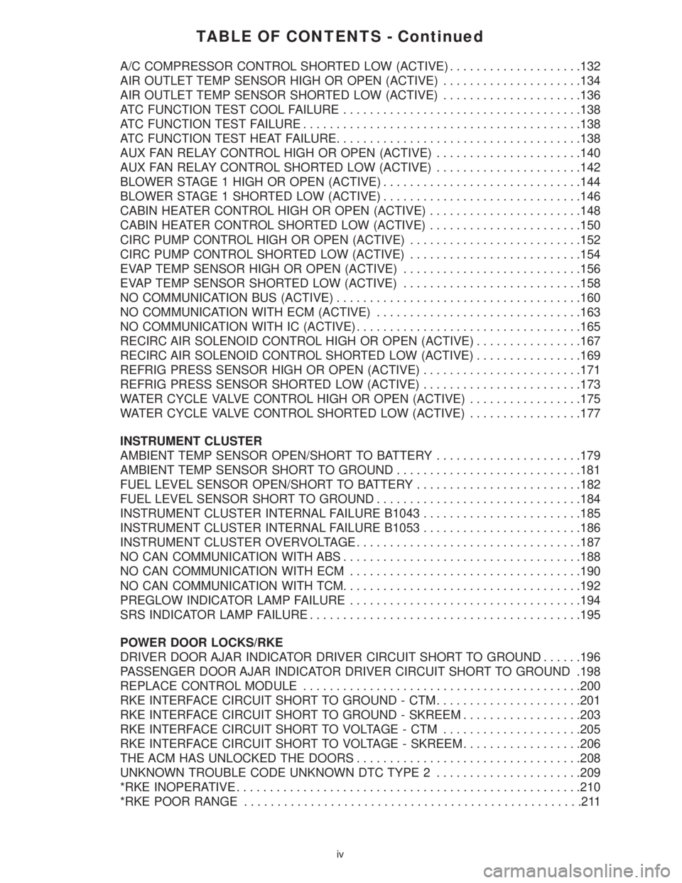
TABLE OF CONTENTS - Continued
A/C COMPRESSOR CONTROL SHORTED LOW (ACTIVE)....................132
AIR OUTLET TEMP SENSOR HIGH OR OPEN (ACTIVE).....................134
AIR OUTLET TEMP SENSOR SHORTED LOW (ACTIVE).....................136
ATC FUNCTION TEST COOL FAILURE....................................138
ATC FUNCTION TEST FAILURE..........................................138
ATC FUNCTION TEST HEAT FAILURE.....................................138
AUX FAN RELAY CONTROL HIGH OR OPEN (ACTIVE)......................140
AUX FAN RELAY CONTROL SHORTED LOW (ACTIVE)......................142
BLOWER STAGE 1 HIGH OR OPEN (ACTIVE)..............................144
BLOWER STAGE 1 SHORTED LOW (ACTIVE)..............................146
CABIN HEATER CONTROL HIGH OR OPEN (ACTIVE).......................148
CABIN HEATER CONTROL SHORTED LOW (ACTIVE).......................150
CIRC PUMP CONTROL HIGH OR OPEN (ACTIVE)..........................152
CIRC PUMP CONTROL SHORTED LOW (ACTIVE)..........................154
EVAP TEMP SENSOR HIGH OR OPEN (ACTIVE)...........................156
EVAP TEMP SENSOR SHORTED LOW (ACTIVE)...........................158
NO COMMUNICATION BUS (ACTIVE).....................................160
NO COMMUNICATION WITH ECM (ACTIVE)...............................163
NO COMMUNICATION WITH IC (ACTIVE)..................................165
RECIRC AIR SOLENOID CONTROL HIGH OR OPEN (ACTIVE)................167
RECIRC AIR SOLENOID CONTROL SHORTED LOW (ACTIVE)................169
REFRIG PRESS SENSOR HIGH OR OPEN (ACTIVE)........................171
REFRIG PRESS SENSOR SHORTED LOW (ACTIVE)........................173
WATER CYCLE VALVE CONTROL HIGH OR OPEN (ACTIVE).................175
WATER CYCLE VALVE CONTROL SHORTED LOW (ACTIVE).................177
INSTRUMENT CLUSTER
AMBIENT TEMP SENSOR OPEN/SHORT TO BATTERY......................179
AMBIENT TEMP SENSOR SHORT TO GROUND............................181
FUEL LEVEL SENSOR OPEN/SHORT TO BATTERY.........................182
FUEL LEVEL SENSOR SHORT TO GROUND...............................184
INSTRUMENT CLUSTER INTERNAL FAILURE B1043........................185
INSTRUMENT CLUSTER INTERNAL FAILURE B1053........................186
INSTRUMENT CLUSTER OVERVOLTAGE..................................187
NO CAN COMMUNICATION WITH ABS....................................188
NO CAN COMMUNICATION WITH ECM...................................190
NO CAN COMMUNICATION WITH TCM....................................192
PREGLOW INDICATOR LAMP FAILURE...................................194
SRS INDICATOR LAMP FAILURE.........................................195
POWER DOOR LOCKS/RKE
DRIVER DOOR AJAR INDICATOR DRIVER CIRCUIT SHORT TO GROUND......196
PASSENGER DOOR AJAR INDICATOR DRIVER CIRCUIT SHORT TO GROUND .198
REPLACE CONTROL MODULE..........................................200
RKE INTERFACE CIRCUIT SHORT TO GROUND - CTM......................201
RKE INTERFACE CIRCUIT SHORT TO GROUND - SKREEM..................203
RKE INTERFACE CIRCUIT SHORT TO VOLTAGE - CTM.....................205
RKE INTERFACE CIRCUIT SHORT TO VOLTAGE - SKREEM..................206
THE ACM HAS UNLOCKED THE DOORS..................................208
UNKNOWN TROUBLE CODE UNKNOWN DTC TYPE 2......................209
*RKE INOPERATIVE....................................................210
*RKE POOR RANGE...................................................211
iv
Page 11 of 2305
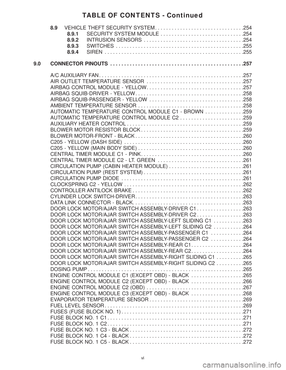
TABLE OF CONTENTS - Continued
8.9VEHICLE THEFT SECURITY SYSTEM................................254
8.9.1SECURITY SYSTEM MODULE..............................254
8.9.2INTRUSION SENSORS....................................254
8.9.3SWITCHES..............................................255
8.9.4SIREN..................................................255
9.0 CONNECTOR PINOUTS................................................257
A/C AUXILIARY FAN....................................................257
AIR OUTLET TEMPERATURE SENSOR...................................257
AIRBAG CONTROL MODULE - YELLOW...................................257
AIRBAG SQUIB-DRIVER - YELLOW.......................................258
AIRBAG SQUIB-PASSENGER - YELLOW..................................258
AMBIENT TEMPERATURE SENSOR......................................258
AUTOMATIC TEMPERATURE CONTROL MODULE C1 - BROWN..............259
AUTOMATIC TEMPERATURE CONTROL MODULE C2.......................259
AUXILIARY HEATER CONTROL..........................................259
BLOWER MOTOR RESISTOR BLOCK.....................................259
BLOWER MOTOR-FRONT - BLACK.......................................260
C205 - YELLOW (DASH SIDE)...........................................260
C205 - YELLOW (MAIN BODY SIDE)......................................260
CENTRAL TIMER MODULE C1 - PINK.....................................260
CENTRAL TIMER MODULE C2 - LT. GREEN...............................261
CIRCULATION PUMP (CABIN HEATER MODULE)...........................261
CIRCULATION PUMP (REST SYSTEM)....................................261
CIRCULATION PUMP DIODE............................................261
CLOCKSPRING C2 - YELLOW...........................................262
CONTROLLER ANTILOCK BRAKE........................................262
CYLINDER LOCK SWITCH-DRIVER.......................................263
DATA LINK CONNECTOR - BLACK........................................263
DOOR LOCK MOTOR/AJAR SWITCH ASSEMBLY-DRIVER C1.................263
DOOR LOCK MOTOR/AJAR SWITCH ASSEMBLY-DRIVER C2.................263
DOOR LOCK MOTOR/AJAR SWITCH ASSEMBLY-LEFT SLIDING C1...........263
DOOR LOCK MOTOR/AJAR SWITCH ASSEMBLY-LEFT SLIDING C2...........264
DOOR LOCK MOTOR/AJAR SWITCH ASSEMBLY-PASSENGER C1............264
DOOR LOCK MOTOR/AJAR SWITCH ASSEMBLY-PASSENGER C2............264
DOOR LOCK MOTOR/AJAR SWITCH ASSEMBLY-REAR C1...................264
DOOR LOCK MOTOR/AJAR SWITCH ASSEMBLY-REAR C2...................264
DOOR LOCK MOTOR/AJAR SWITCH ASSEMBLY-RIGHT SLIDING C1..........265
DOOR LOCK MOTOR/AJAR SWITCH ASSEMBLY-RIGHT SLIDING C2..........265
DOSING PUMP........................................................265
ENGINE CONTROL MODULE C1 (EXCEPT OBD) - BLACK...................265
ENGINE CONTROL MODULE C2 (EXCEPT OBD) - BLACK...................266
ENGINE CONTROL MODULE C2 (OBD)...................................267
ENGINE CONTROL MODULE C3 (EXCEPT OBD) - BLACK...................268
EVAPORATOR TEMPERATURE SENSOR..................................269
FUEL LEVEL SENSOR..................................................269
FUSES (FUSE BLOCK NO. 1)............................................271
FUSE BLOCK NO. 1 C1.................................................271
FUSE BLOCK NO. 1 C2.................................................271
FUSE BLOCK NO. 1 C3 - BLACK.........................................272
FUSE BLOCK NO. 1 C4 - BLACK.........................................272
FUSE BLOCK NO. 1 C5 - BLACK.........................................272
vi
Page 12 of 2305
TABLE OF CONTENTS - Continued
FUSES (FUSE BLOCK NO. 2)............................................274
FUSES (FUSE BLOCK NO. 3)............................................276
FUSES (FUSE/RELAY BLOCK)...........................................278
HOOD AJAR SWITCH - BLACK...........................................278
HORN (VTSS).........................................................278
IGNITION LOCK SWITCH - BLACK........................................278
INSTRUMENT CLUSTER C1.............................................279
INSTRUMENT CLUSTER C2 - WHITE.....................................279
INTRUSION SENSOR NO. 1 - BLACK.....................................279
INTRUSION SENSOR NO. 2 - BLACK.....................................279
INTRUSION SENSOR NO. 3 - BLACK.....................................280
MASTER DOOR LOCK SWITCH..........................................280
PANIC ALARM SWITCH - BLACK.........................................280
FUSES (PDC).........................................................281
RADIO C1 - BLACK....................................................282
RADIO C2............................................................282
RECIRCULATED AIR SOLENOID VALVE...................................282
REFRIGERANT PRESSURE SENSOR.....................................282
A/C AUXILIARY FAN RELAY (RELAY BLOCK)...............................284
CIRCULATION PUMP RELAY-CABIN HEATER MODULE (RELAY BLOCK).......284
D+ RELAY NO. 2 (RELAY BLOCK)........................................284
FAN STAGE 1 RELAY (RELAY BLOCK)....................................284
OPTIONAL EQUIPMENT RELAY (RELAY BLOCK)...........................284
REMOTE KEYLESS ENTRY ANTENNA....................................284
SEAT BELT SWITCH...................................................284
SEAT BELT TENSIONER-DRIVER - YELLOW...............................285
SEAT BELT TENSIONER-PASSENGER - YELLOW...........................285
SECURITY SYSTEM MODULE C1 - BROWN...............................285
SECURITY SYSTEM MODULE C2 - LT. GREEN.............................286
SENTRY KEY REMOTE ENTRY MODULE (SKREEM)........................286
SHIFTER ASSEMBLY - BLACK...........................................286
SIREN - BLACK.......................................................286
STEERING ANGLE SENSOR............................................287
TOWING/INTRUSION SENSOR ON/OFF SWITCH...........................287
TRANSMISSION CONTROL MODULE C1 - BLACK..........................287
TRANSMISSION CONTROL MODULE C2 - BLACK..........................288
WATER CYCLE VALVE..................................................288
WINDOW DEFOGGER-LEFT REAR.......................................288
WINDOW DEFOGGER-RIGHT REAR......................................288
10.0 SCHEMATIC DIAGRAMS................................................289
10.1AIRBAG SYSTEM.................................................289
10.2COMMUNICATION................................................290
10.2.1COMMUNICATION K-LINES................................290
10.2.2CAN BUS NETWORK......................................291
10.3HEATING & A/C...................................................292
10.3.1AUTOMATIC TEMPERATURE CONTROL (ATC)................292
10.3.2CABIN HEATER MODULE (CHM)............................293
10.3.3HEATER BOOSTER MODULE (HBM).........................294
10.4INSTRUMENT CLUSTER...........................................295
vii
Page 20 of 2305
Compres SO Accel (Compressor Shut Off - Due
To Acceleration)
The Engine Control Module transmits this data. A
status of9YES9indicates that the compressor shut
off because of an acceleration request. A status of
9NO9indicates that there is no acceleration request.
If shut off due to an acceleration request, the
compress will switch on again after 20 seconds. In
addition, the original acceleration request can no
longer exist for the ECM to acknowledge a subse-
quent request. In the event of a CAN Bus commu-
nication failure,9NO9is displayed as a substitute
value.
Compres SO W/E-Off (Compressor Shut Off -
Due to Emergency Off)
The Engine Control Module transmits this data. A
status of9YES9indicates that the compressor shut
off because of an emergency off request. A status of
9NO9indicates that there is no emergency off re-
quest. In the event of a CAN Bus communication
failure, the last stored value is displayed as a
substitute value.
Auxiliary Fan
The ATC Module transmits this data. A status of
9ON9indicates that the auxiliary fan is operational.
A status of9OFF9indicates that the auxiliary fan is
not operational. The Auxiliary Fan normally oper-
ates when refrigerant head pressure exceeds 290
PSI and coolant temperature exceeds 221ÉF. In the
event of a CAN Bus communication failure, 257ÉF is
displayed for coolant temperature (in Sensors) and
the Auxiliary Fan will run continuously.
Light PB CTRL Module
This input displays a status of9Bright9for positive
dimmer switch operation and9Dimmed9for nega-
tive dimmer switch operation. In the event of a CAN
Bus communication failure,9Bright9is displayed.
3.3.2 CABIN HEATER MODULE (CHM) &
HEATER BOOSTER MODULE (HBM)
3.3.2.1 SYSTEM DESCRIPTION
WARNING: NEVER OPERATE THE HEATER
IN AN ENCLOSED AREA THAT DOES NOT
HAVE EXHAUST VENTILATION FACILITIES.
ALWAYS VENT THE HEATER'S EXHAUST
WHEN OPERATING THE HEATER. REFER TO
(VENTING THE HEATER'S EXHAUST(
BELOW FOR PROPER EXHAUST VENTING
INSTRUCTIONS. FAILURE TO FOLLOW
THESE INSTRUCTIONS CAN RESULT IN
PERSONAL INJURY OR DEATH.
WARNING: ALLOW THE HEATER ASSEMBLY TO
COOL BEFORE PERFORMING A COMPONENT
INSPECTION/REPAIR/REPLACEMENT. FAILURE
TO FOLLOW THESE INSTRUCTIONS CAN
RESULT IN PERSONAL INJURY OR DEATH.
WARNING: ALWAYS DISCONNECT THE
VEHICLE'S BATTERY PRIOR TO
PERFORMING ANY TYPE OF WORK ON THE
HEATER ASSEMBLY. FAILURE TO FOLLOW
THESE INSTRUCTIONS CAN RESULT IN
PERSONAL INJURY OR DEATH.
WARNING: NEVER ATTEMPT TO REPAIR THE
HEATER ASSEMBLY OR ANY OF ITS
INTERNAL COMPONENTS. ALWAYS
PERFORM HEATER COMPONENT
REPLACEMENT IN ACCORDANCE WITH THE
SERVICE INFORMATION. FAILURE TO
FOLLOW THESE INSTRUCTIONS CAN
RESULT IN PERSONAL INJURY OR DEATH.
CAUTION: Always Perform The Heater
Pre-Test (In The Diagnostic Procedures) Prior
To Performing Any Other Test On The Heater
For The Test Result To Be Valid.
NOTE: Do not disconnect the vehicle's
battery or the heater's main power-supply
while the heater is in operation or in
run-down mode. Failure to follow these
instructions may result in excess emissions
from the heater.
NOTE: Failure to prime the Dosing Pump
after draining the fuel line will prevent heater
activation during the first attempt to start the
unit. This may also set a Diagnostic Trouble
Code (DTC) in the control unit's memory. Do
not perform the Dosing Pump Priming
Procedure if an attempt was made to start the
heater without priming the Dosing Pump
first. This will put excess fuel in the heater
module and cause smoke to emit from the
heater's exhaust pipe when heater activation
occurs.
NOTE: Waxed fuel can obstruct the fuel line
and reduce flow. Check for the appropriate
winter grade fuel and replace as necessary.
The Cabin Heater Assembly and Heater Booster
Assembly are supplemental type heaters designed
to pre-heat the engine's coolant in order to supply
the vehicle's occupants with heat prior to the engine
7
GENERAL INFORMATION
Page 21 of 2305
reaching operating temperature. The heater's con-
trol unit controls and monitors combustion opera-
tion through various inputs and outputs that are
contained inside the heater assembly. The supple-
mental heater connects to the vehicle's heater hoses
and uses a separate fuel supply line and fuel pump
that connects to the vehicle's fuel tank. Unlike the
Heater Booster, the Cabin Heater Assembly has an
integral coolant pump which allows heater opera-
tion without the vehicle's engine running. In addi-
tion, a programmable timer module can also be
added to this system. Neither the Cabin Heater
Assembly nor the Heater Booster Assembly are
connected to the CAN Bus. Communication be-
tween the heater's control unit and the DRBIIIt
occurs through the Diagnostic Link Connector
(DLC) via a K-Line.
3.3.2.2 VENTING THE HEATER'S EXHAUST
WARNING: NEVER OPERATE THE HEATER
IN AN ENCLOSED AREA THAT DOES NOT
HAVE EXHAUST VENTILATION FACILITIES.
ALWAYS VENT THE HEATER'S EXHAUST
WHEN OPERATING THE HEATER. FAILURE
TO FOLLOW THESE INSTRUCTIONS CAN
RESULT IN PERSONAL INJURY OR DEATH.
WARNING:
ALLOW THE HEATER ASSEMBLY TO
COOL BEFORE PERFORMING A COMPONENT
INSPECTION/REPAIR/REPLACEMENT. FAILURE
TO FOLLOW THESE INSTRUCTIONS CAN
RESULT IN PERSONAL INJURY OR DEATH.
CAUTION: When using a powered exhaust
ventilation system, do not attach the exhaust
ventilation hose directly to the heater's
exhaust pipe. Too much suction can prevent
heater operation.
When using a powered exhaust ventilation sys-
tem, affix the ventilation hose to the heater's ex-
haust pipe or to the vehicle in such a manor that the
end of the ventilation hose remains approximately
three inches away from the end of the heater's
exhaust pipe.
When using a non-powered exhaust ventilation
system, affix the ventilation hose directly to the
heater's exhaust pipe.
3.3.2.3 SYSTEM DIAGNOSTICS
CAUTION: Always Perform The Heater
Pre-Test (In The Diagnostic Procedures) Prior
To Performing Any Other Test For The Test
Result To Be Valid.
Fault detection is through stored Diagnostic
Trouble Codes (DTCs). DTCs are displayed by the
DRBIIIt. The heater's control unit will store up to
five DTCs in its memory. If the control unit detects
a new fault in the system, one that is not already
stored in its memory, it will clear the oldest of the
five stored DTCs, and it will store the new fault's
DTC. If the control unit detects a reoccurrence of a
stored fault, it will overwrite that fault's DTC with
the most recent occurrence.
DIAGNOSTIC TIPS
SENSOR VALUES
Operating Voltage
The normal range for the Operating Voltage is from
10 volts to 15 volts. The value indicates the voltage
at the heater 's Fused B+ terminal.
Heating Capacity
The normal range for the heating capacity is from
0% to 100%. The value indicates the momentary
output of the auxiliary heater in % of the maximum
output.
Coolant Temperature
The value indicates the current coolant tempera-
ture.
Flame Sensor Resistance
The normal range for the Flame Sensor is from 750
ohms to 2270 ohms. The value indicates the mo-
mentary resistance of the Flame Sensor.
INPUT/OUTPUT STATUS
Dosing Pump
A status of9ON9indicates that the Dosing Pump is
operational. A status of9OFF9indicates the Dosing
Pump is not operational.
Glow Pin
A status of9ON9indicates that the Glow Pin is
energized. A status of9OFF9indicates the Glow Pin
is not energized.
Combustion Fan
A status of9ON9indicates that the Combustion Fan
is operational. A status of9OFF9indicates the
Combustion Fan is not operational.
Circulation Pump
A status of9ON9indicates that the Circulation
Pump is operational. A status of9OFF9indicates the
Circulation Pump is not operational.
Front End Blower
A status of9ON9indicates that the Blower Motor is
operational. A status of9OFF9indicates the Blower
Motor is not operational.
8
GENERAL INFORMATION
Page 89 of 2305
Symptom List:
COMBUST FAN SHORTED
COMBUST FAN SPEED INCORRECT
COMBUSTION FAN OPEN
Test Note: All symptoms listed above are diagnosed using the same tests.
The title for the tests will be COMBUST FAN SHORTED.
POSSIBLE CAUSES
COMBUSTION AIR FAN
TEST ACTION APPLICABILITY
1WARNING: NEVER OPERATE THE HEATER IN AN ENCLOSED AREA
THAT DOES NOT HAVE EXHAUST VENTILATION FACILITIES. ALWAYS
VENT THE EXHAUST WHEN OPERATING THE HEATER. FAILURE TO
FOLLOW THESE INSTRUCTIONS CAN RESULT IN PERSONAL INJURY
OR DEATH.
WARNING: ALLOW THE HEATER ASSEMBLY TO COOL BEFORE PER-
FORMING A COMPONENT INSPECTION/REPAIR/REPLACEMENT. FAIL-
URE TO FOLLOW THESE INSTRUCTIONS CAN RESULT IN PERSONAL
INJURY OR DEATH.
CAUTION: DO NOT PERFORM THIS TEST UNLESS DIRECTED HERE BY
THE HEATER PRE-TEST. ALWAYS PERFORM THE HEATER PRE-TEST
PRIOR TO PERFORMING ANY OTHER TEST FOR THE RESULT TO BE
VALID.
Turn the ignition off.
View repairAll
Repair
Replace the Cabin Heater Assembly or Heater Booster Assembly
in accordance with the Service Information.
Perform HEATER VERIFICATION TEST - VER 1.
76
CABIN HEATER
Page 96 of 2305
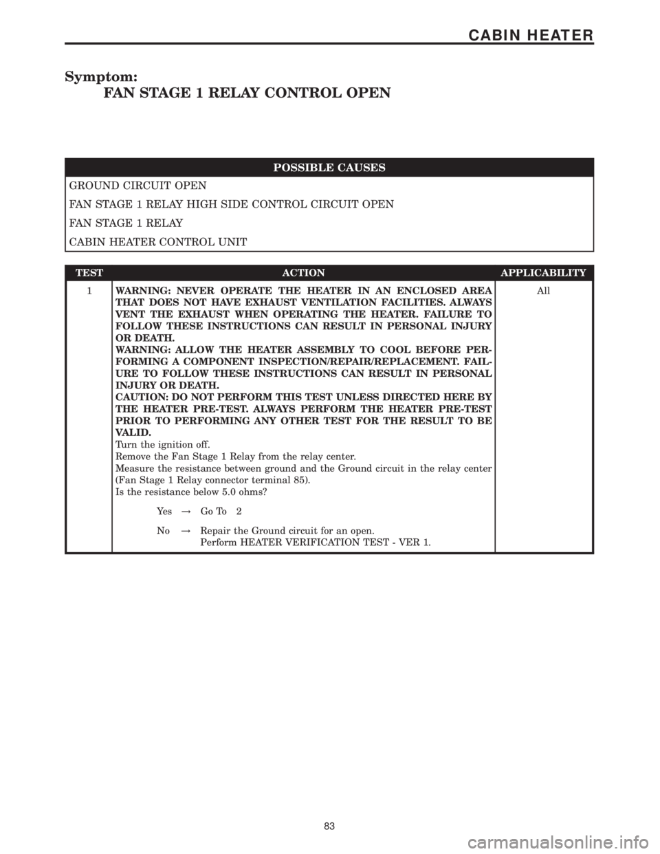
Symptom:
FAN STAGE 1 RELAY CONTROL OPEN
POSSIBLE CAUSES
GROUND CIRCUIT OPEN
FAN STAGE 1 RELAY HIGH SIDE CONTROL CIRCUIT OPEN
FAN STAGE 1 RELAY
CABIN HEATER CONTROL UNIT
TEST ACTION APPLICABILITY
1WARNING: NEVER OPERATE THE HEATER IN AN ENCLOSED AREA
THAT DOES NOT HAVE EXHAUST VENTILATION FACILITIES. ALWAYS
VENT THE EXHAUST WHEN OPERATING THE HEATER. FAILURE TO
FOLLOW THESE INSTRUCTIONS CAN RESULT IN PERSONAL INJURY
OR DEATH.
WARNING: ALLOW THE HEATER ASSEMBLY TO COOL BEFORE PER-
FORMING A COMPONENT INSPECTION/REPAIR/REPLACEMENT. FAIL-
URE TO FOLLOW THESE INSTRUCTIONS CAN RESULT IN PERSONAL
INJURY OR DEATH.
CAUTION: DO NOT PERFORM THIS TEST UNLESS DIRECTED HERE BY
THE HEATER PRE-TEST. ALWAYS PERFORM THE HEATER PRE-TEST
PRIOR TO PERFORMING ANY OTHER TEST FOR THE RESULT TO BE
VALID.
Turn the ignition off.
Remove the Fan Stage 1 Relay from the relay center.
Measure the resistance between ground and the Ground circuit in the relay center
(Fan Stage 1 Relay connector terminal 85).
Is the resistance below 5.0 ohms?All
Ye s!Go To 2
No!Repair the Ground circuit for an open.
Perform HEATER VERIFICATION TEST - VER 1.
83
CABIN HEATER
Page 97 of 2305
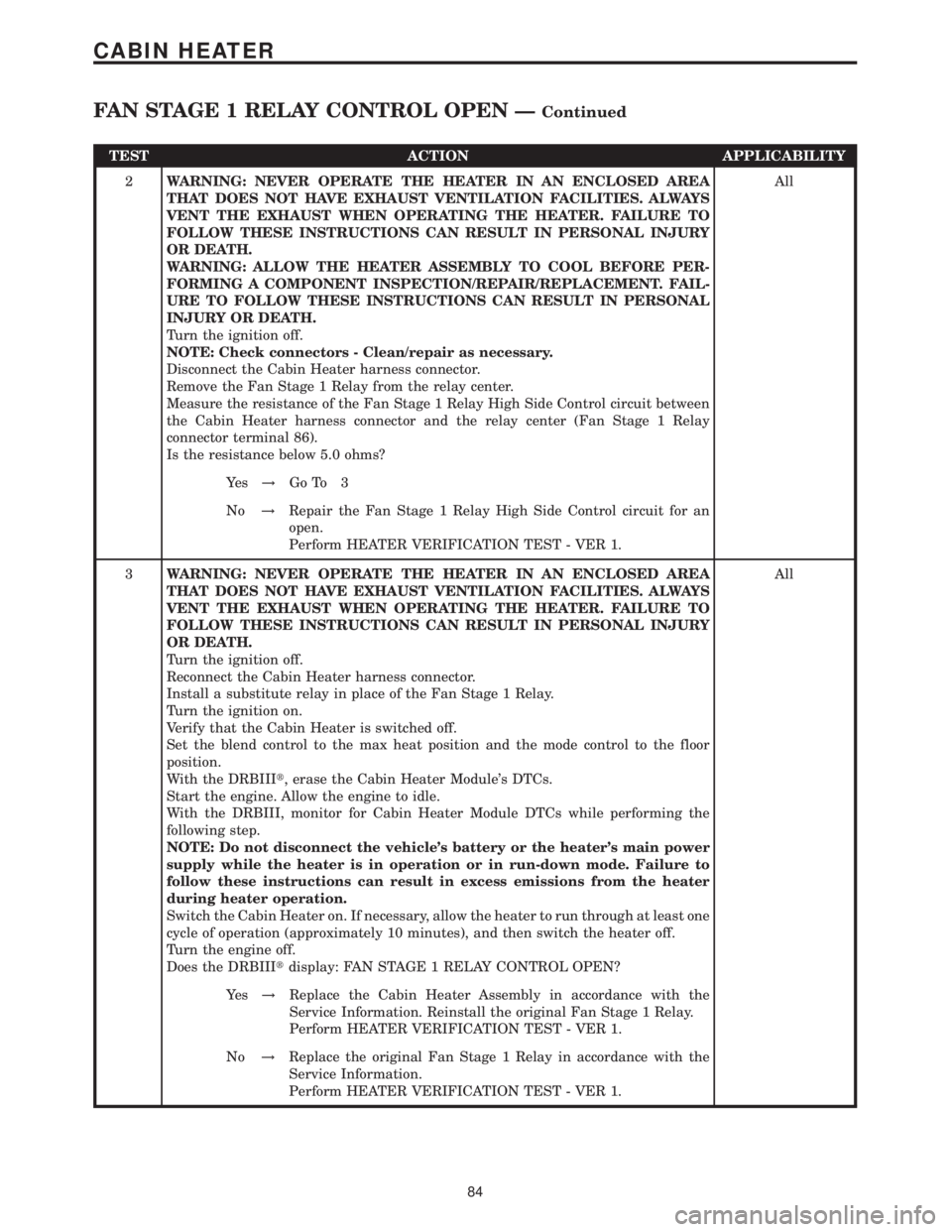
TEST ACTION APPLICABILITY
2WARNING: NEVER OPERATE THE HEATER IN AN ENCLOSED AREA
THAT DOES NOT HAVE EXHAUST VENTILATION FACILITIES. ALWAYS
VENT THE EXHAUST WHEN OPERATING THE HEATER. FAILURE TO
FOLLOW THESE INSTRUCTIONS CAN RESULT IN PERSONAL INJURY
OR DEATH.
WARNING: ALLOW THE HEATER ASSEMBLY TO COOL BEFORE PER-
FORMING A COMPONENT INSPECTION/REPAIR/REPLACEMENT. FAIL-
URE TO FOLLOW THESE INSTRUCTIONS CAN RESULT IN PERSONAL
INJURY OR DEATH.
Turn the ignition off.
NOTE: Check connectors - Clean/repair as necessary.
Disconnect the Cabin Heater harness connector.
Remove the Fan Stage 1 Relay from the relay center.
Measure the resistance of the Fan Stage 1 Relay High Side Control circuit between
the Cabin Heater harness connector and the relay center (Fan Stage 1 Relay
connector terminal 86).
Is the resistance below 5.0 ohms?All
Ye s!Go To 3
No!Repair the Fan Stage 1 Relay High Side Control circuit for an
open.
Perform HEATER VERIFICATION TEST - VER 1.
3WARNING: NEVER OPERATE THE HEATER IN AN ENCLOSED AREA
THAT DOES NOT HAVE EXHAUST VENTILATION FACILITIES. ALWAYS
VENT THE EXHAUST WHEN OPERATING THE HEATER. FAILURE TO
FOLLOW THESE INSTRUCTIONS CAN RESULT IN PERSONAL INJURY
OR DEATH.
Turn the ignition off.
Reconnect the Cabin Heater harness connector.
Install a substitute relay in place of the Fan Stage 1 Relay.
Turn the ignition on.
Verify that the Cabin Heater is switched off.
Set the blend control to the max heat position and the mode control to the floor
position.
With the DRBIIIt, erase the Cabin Heater Module's DTCs.
Start the engine. Allow the engine to idle.
With the DRBIII, monitor for Cabin Heater Module DTCs while performing the
following step.
NOTE: Do not disconnect the vehicle's battery or the heater's main power
supply while the heater is in operation or in run-down mode. Failure to
follow these instructions can result in excess emissions from the heater
during heater operation.
Switch the Cabin Heater on. If necessary, allow the heater to run through at least one
cycle of operation (approximately 10 minutes), and then switch the heater off.
Turn the engine off.
Does the DRBIIItdisplay: FAN STAGE 1 RELAY CONTROL OPEN?All
Ye s!Replace the Cabin Heater Assembly in accordance with the
Service Information. Reinstall the original Fan Stage 1 Relay.
Perform HEATER VERIFICATION TEST - VER 1.
No!Replace the original Fan Stage 1 Relay in accordance with the
Service Information.
Perform HEATER VERIFICATION TEST - VER 1.
84
CABIN HEATER
FAN STAGE 1 RELAY CONTROL OPEN ÐContinued