instrument panel MERCEDES-BENZ SPRINTER 2006 Service Manual
[x] Cancel search | Manufacturer: MERCEDES-BENZ, Model Year: 2006, Model line: SPRINTER, Model: MERCEDES-BENZ SPRINTER 2006Pages: 2305, PDF Size: 48.12 MB
Page 15 of 2305
secured to the floor under the Driver seat and
receives power from the Fuse Block No. 1. When-
ever the ignition key is turned to the run or start
position, the ACM performs a system test. The ACM
cannot be repaired or adjusted.
The microprocessor in the ACM monitors the
internal and external airbag system electrical cir-
cuits to determine the system readiness. When a
monitored system is determine to be out of range,
the ACM will set both active and stored diagnostic
trouble codes (DTC). The ACM also contains an
energy-storage capacitor. This capacitor stores
enough electrical energy to deploy the front airbag
components for two seconds following a battery
disconnect or failure during an impact.
The Accelerometer in the ACM is used to sense
the rate of vehicle deceleration, provide verification
of the direction and severity of an impact. When the
preprogrammed conditions are met, the ACM sends
an electrical signal to deploy the appropriate front
airbag system components and a deployment noti-
fication.
To provide an accident response notification, the
ACM is hardwired to the Central Timer module
(CTM) and Engine Control Module (ECM). When a
deployment occurs the ACM provides a 50ms 10.0
volt pulse to the CTM and ECM. When the Accident
Report notification signal is received the CTM un-
locks the door locks and the ECM stalls the engine.
The Accident signal will set a DTC in the CTM and
the door locks will not work until the DTC has been
erased. The ECM will set a DTC if the Accident
Report circuit is shorted to battery voltage. The
ACM saves the deployment record and after three
deployments the ACM must be replaced. The
DRBIIItcan be used to test the Accident Report
Notification feature: select the SYSTEM TEST from
the ACM main menu. Then select the Analog Crash
Output System Test.
The ACM is hardwired to the Instrument Cluster
(MIC) to control Warning Indicator (SRS indicator).
When DTCs becomes activate, the ACM illuminates
the Warning Indicator by pulling the indicator
circuit low. The SRS indicator is the only point at
which the customer can observe symptoms of a
system malfunction.
As part of the system test the ACM illuminates
the Warning Indicator on for 4.0 second bulb test.
After the lamp check, if the indicator turns off, it
means that the ACM has checked the system and
found it to be free of discernible malfunctions.
NON-CRITICAL DTCs
If the lamp comes on and stays on for a period
longer than 4.0 seconds (about 10.0 seconds) is
usually a stored DTC (intermittent problem) in the
system.
CRITICAL DTCs
DTCs that could lead to a condition where the
safety devises may not deploy or incorrectly deploy.
In the event of such a DTC, the safety of the vehicle
occupants can no longer be guaranteed. If the lamp
remains on, there could be an active DTC in the
system. Some DTCs, Internal Module and squib
DTCs, will keep the indicator illuminated even if
the codes are no longer active.
ACM NOT CONFIGURED FOR PASSENGER
AIRBAG AND TENSIONER
If after replacing the ACM the Airbag Warning
Indicator flashes continuously the ACM must be
configured for the Passenger Airbag and Tensioner.
Select Miscellaneous from the ACM main menu and
configure the Passenger Airbag Tensioner squibs.
WARNING:THE AIRBAG SYSTEM IS A
SENSITIVE, COMPLEX ELECTROMECHANICAL
UNIT. BEFORE ATTEMPTING TO DIAGNOSE OR
SERVICE ANY AIRBAG SYSTEM OR RELATED
STEERING WHEEL, STEERING COLUMN, OR
INSTRUMENT PANEL COMPONENTS YOU MUST
FIRST DISCONNECT AND ISOLATE THE
BATTERY NEGATIVE (GROUND) CABLE. WAIT
TWO MINUTES FOR THE SYSTEM CAPACITOR
TO DISCHARGE BEFORE FURTHER SYSTEM
SERVICE. THIS IS THE ONLY SURE WAY TO
DISABLE THE AIRBAG SYSTEM. FAILURE TO
DO THIS COULD RESULT IN ACCIDENTAL
AIRBAG DEPLOYMENT AND POSSIBLE
PERSONAL INJURY.
WARNING: TO AVOID PERSONAL INJURY OR
DEATH, NEVER STRIKE OR KICK THE
AIRBAG CONTROL MODULE, AS IT CAN
DAMAGE THE IMPACT SENSOR OR AFFECT
ITS CALIBRATION.
WARNING: IF AN AIRBAG CONTROL
MODULE IS ACCIDENTALLY DROPPED
DURING SERVICE, THE MODULE MUST BE
SCRAPPED AND REPLACED WITH A NEW
UNIT. FAILURE TO TAKE THE PROPER
PRECAUTIONS COULD RESULT IN
ACCIDENTAL AIRBAG DEPLOYMENT AND
PERSONAL INJURY OR DEATH.
3.1.1 DRIVER AIRBAG
The airbag protective trim cover is the most
visible part of the driver side airbag system. The
airbag is mounted directly to the steering wheel.
Located under the trim cover are the airbag cushion
and the airbag cushion supporting components.
2
GENERAL INFORMATION
Page 16 of 2305
When supplied with the proper electrical signal, the
inflator discharged the gas directly into the cush-
ion. The airbag cannot be repaired, and must be
replaced if deployed or in any way damaged.
WARNING: THE DRIVER AIRBAG MODULE
CONTAINS ARGON GAS PRESSURIZED TO
OVER 17236.89 Kpa (2500 PSI). DO NOT
ATTEMPT TO DISMANTLE AN AIRBAG
MODULE OR TAMPER WITH ITS INFLATOR.
DO NOT PUNCTURE, INCINERATE, OR
BRING INTO CONTACT WITH ELECTRICITY.
DO NOT STORE AT TEMPERATURE
EXCEEDING 93ÉC (200ÉF). REPLACE AIRBAG
SYSTEM COMPONENTS ONLY WITH PARTS
SPECIFIED IN THE CHRYSLER MOPAR
PARTS CATALOG. SUBSTITUTE PARTS MAY
APPEAR INTER-CHANGEABLE, BUT
INTERNAL DIFFERENCES MAY RESULT IN
INFERIOR OCCUPANT PROTECTION. THE
FASTENERS, SCREWS, AND BOLTS
ORIGINALLY USED FOR THE AIRBAG
SYSTEM COMPONENTS HAVE SPECIAL
COATINGS AND ARE SPECIFICALLY
DESIGNED FOR THE AIRBAG SYSTEM. THEY
MUST NEVER BE REPLACED WITH ANY
SUBSTITUTES. ANY TIME A NEW FASTENER
IS NEEDED, REPLACE IT WITH THE
CORRECT FASTENERS PROVIDED IN THE
SERVICE PACKAGE OR SPECIFIED IN THE
MOPAR PARTS CATALOG. FAILURE TO
TAKE THE PROPER PRECAUTIONS COULD
RESULT IN ACCIDENTAL AIRBAG
DEPLOYMENT AND PERSONAL INJURY OR
DEATH.
3.1.2 CLOCKSPRING
The clockspring is mounted on the steering col-
umn under the steering wheel. This assembly con-
sists of a plastic housing which contains a flat,
ribbon-like, electrically conductive tape that winds
and unwinds with the steering wheel rotation. The
clockspring is used to maintain a continuous elec-
trical circuit between the instrument panel wiring
and the driver airbag and the horn. The clockspring
must be properly centered when it is reinstalled on
the steering column following any service proce-
dure, or it could be damaged. The clockspring can-
not be repaired and it must be replaced.
3.1.3 PASSENGER AIRBAG
The Passenger Airbag is optional equipment.
When supplied with the proper electrical signal the
passenger airbag inflator discharges the gas di-rectly into the cushion. The airbag module cannot
be repaired, and must be replaced if deployed or in
any way damaged.
WARNING: THE PASSENGER AIRBAG
MODULE CONTAINS ARGON GAS
PRESSURIZED TO 17236.89 Kpa (2500 PSI).
DO NOT ATTEMPT TO DISMANTLE AN
AIRBAG MODULE OR TAMPER WITH ITS
INFLATOR. DO NOT PUNCTURE,
INCINERATE, OR BRING INTO CONTACT
WITH ELECTRICITY. DO NOT STORE AT
TEMPERATURE EXCEEDING 93ÉC (200ÉF).
REPLACE AIRBAG SYSTEM COMPONENTS
ONLY WITH PARTS SPECIFIED IN THE
MOPAR PARTS CATALOG. SUBSTITUTE
PARTS MAY APPEAR INTER-CHANGEABLE,
BUT INTERNAL DIFFERENCES MAY RESULT
IN INFERIOR OCCUPANT PROTECTION. THE
FASTENERS, SCREWS, AND BOLTS
ORIGINALLY USED FOR THE AIRBAG
SYSTEM COMPONENTS HAVE SPECIAL
COATINGS AND ARE SPECIFICALLY
DESIGNED FOR THE AIRBAG SYSTEM. THEY
MUST NEVER BE REPLACED WITH ANY
SUBSTITUTES. ANY TIME A NEW FASTENER
IS NEEDED, REPLACE IT WITH THE
CORRECT FASTENERS PROVIDED IN THE
SERVICE PACKAGE OR SPECIFIED IN THE
MOPAR PARTS CATALOG. FAILURE TO
TAKE THE PROPER PRECAUTIONS COULD
RESULT IN ACCIDENTAL AIRBAG
DEPLOYMENT AND PERSONAL INJURY OR
DEATH.
3.1.4 SEAT BELT TENSIONERS
Front seat belt systems incorporate a Driver and
optional Passenger Seat Belt Tensioner Retractors.
At the onset of an impact event each tensioner uses
a pyrotechnic device, which is triggered simulta-
neously with the front airbags, to rapidly retract
the seat belts. With the slack removed, the occu-
pant's forward motion in an impact will be reduced
as will the likelihood of contacting interior compo-
nents. After an impact that deploys the airbag, the
seat belt tensioner assembly must be replaced. The
ACM module monitors the Seat Belt Tensioners
circuit resistance and reports active and stored
DTCs if any problem is found. Follow all of the
safety procedures when servicing tensioner.
3.1.5 SPECIAL TOOLS
Airbag load tools 8310 and 8443 are used in some
airbag diagnostic test. The load tools contain fixed
resistive loads, jumpers and adapters. The fixed
3
GENERAL INFORMATION
Page 23 of 2305
the A-pillar. The SKREEM receives radio messages
from the RKE transmitter (fob) and sends com-
mands via the RKE Interface circuit to the CTM. If
the vehicle is equipped with VTSS, the Security
System Module will be connected in series between
the SKREEM and the CTM.
Confirmation of the RKE Lock/Unlock state is
accomplished via the turn signals. When the vehicle
is locked via RKE the turn signals will flash three
times. When it is unlocked via RKE, the turn
signals will flash one time. If the vehicle has been
unlocked via RKE and no door is opened within 40
seconds, the entire vehicle will be locked again
automatically.
If a transmitter (fob) is operated more than 255
times in succession beyond the range of the receiver
(SKREEM), the RKE portion of the key will become
inoperative. In order to put it back in synchroniza-
tion it will be necessary to have ALL the other
transmitters that are used with this vehicle avail-
able and follow the following procedure:
1. Cycle the ignition on and off 2 times within 6
seconds (leave in off position).
2. Press the lock or unlock button of the disabled
transmitter within 3 seconds of turning the
ignition off.
3. Press any button (lock or unlock) 3 more times
within 6 seconds.
4. Wait 10 seconds.
5. Press any button of ALL other transmitters
belonging to this vehicle at least once within
the next 20 seconds.
For problems related to the Immobilizer function
of the SKREEM, see Service Information.
3.5.3 AUTO DOOR LOCKS
Whenever the engine is started, the CTM receives
a message to lock all doors except the drivers door.
This is accomplished through the D+ Relay. The D+
Relay is controlled by the Instrument Cluster which
receives a command from the ECM that the engine
is running. This relay supplies power to the CTM
(for auto locking), the daytime running lamps and
the rear window defogger.
3.5.4 ACCIDENT RESPONSE
The CTM is hardwired to the Airbag Control
Module through the Enhanced Accident Report
Driver circuit. Anytime the vehicle airbags are
deployed, the CTM will unlock all doors and a
9Crash9DTC will be stored in memory. The door
locks will be inoperative until that code is cleared. If
the vehicle is severly jarred, but not enough to
deploy the airbags, it is possible that the DTC could
be set and therefore the door locks would be inop-
erable. Whenever the door locks are not opera-tional, use the DRBIII and check DTC's . If the code
9ACM has unlocked the doors9appears, use the
DRBIII and erase it.
3.6 VEHICLE THEFT SECURITY SYSTEM
(VTSS)
The Security System Module (SSM) is located
under the driver's seat. The SSM communicates
with the DRBIII over the K-line. If equipped the
Vehicle Theft Security System will monitor the
following:
²door jamb switches
²hood ajar switch
²ignition switch
²interior of the vehicle for movement
²longitudinal and transverse movement of the
vehicle
²rear defogger grids for glass breakage
²trailer connector
To arm the system the hood and all of the doors
must be closed when the vehicle is locked with the
RKE transmitter or with the use of the key in the
driver door. If the key is used, it must be held in the
lock position for 2 seconds. When the system is first
activated, the hazard lamps will flash 3 times. Also
with the system armed, the Towing/Intrusion Sen-
sor On/Off Switch indicator will flash to indicate an
armed system. To disarm the system use the RKE
or the driver door lock cylinder. Unlocking and
opening one of the other doors with the system
armed will trip the vehicle theft security system.
Interior monitoring is done by the use of an
Intrusion Sensor located in the front headliner and
with one or two sensors in the ceiling of the cargo
area depending on how the vehicle is equipped.
Monitoring of the interior of the vehicle will begin
after the system has been armed for 30 seconds. The
on/off switch located on the instrument panel can be
used to turn off this feature with the ignition switch
in either the Locked/Off or ACC position. The vehi-
cle tow-monitoring feature can also be switched off
using this switch. Re-locking the vehicle a second
time will reactivate these features.
If a trailer is connected to the vehicle when the
system is armed, the SSM will sense a resistance
change on the turn signal circuits if the trailer
harness becomes disconnected and will trip the
alarm.
Tripping the vehicle theft security system will
cause the hazard lamps to flash and the siren to
sound at 30-second intervals. The siren is equipped
with it's own self-contained battery. In the event the
vehicle's battery power is disconnected the siren
will continue to sound on it's own.
10
GENERAL INFORMATION
Page 322 of 2305
1.0 INTRODUCTION
The procedures contained in this manual include
all the specifications, instructions, and graphics
needed to diagnose the Sprinter Chassis system
problems: Bosch 5.7 ABS/ESP/TCS (ASR) Braking
System. The diagnostics in this manual are based
on the failure condition or symptom being present
at time of diagnosis.
Please follow the recommendations below when
choosing your diagnostic path.
1. First make sure the DRBIIItis communicating
with the vehicle system being diagnosed. If the
DRBIIItdisplays a ``No Response'' condition, you
must diagnose that first.
2. Read DTC's (diagnostic trouble codes) with the
DRBIIIt.
3. If no DTC's are present, identify the customer
complaint.
4. Once the DTC or customer complaint is iden-
tified locate the matching test in the Table of
Contents and begin to diagnose the system.
All component location views are in Section 8.0.
All connector pinouts are in Section 9.0. All sche-
matics are in Section 10.0.
When repairs are required, refer to the appropri-
ate service manual for the proper removal and
repair procedure.
Diagnostic procedures change every year. New
diagnostic systems may be added; carryover sys-
tems maybe enhanced. READ THIS MANUAL BE-
FORE TRYING TO DIAGNOSE A VEHICLE DI-
AGNOSTIC TROUBLE CODE. It is recommended
that you review the entire manual to become famil-
iar with all new and changed diagnostic procedures.
This manual reflects many suggested changes
from readers of past issues. After using this man-
ual, if you have any comments or recommendations,
please fill out the form at the back of the manual
and mail it back.
1.1 SYSTEM COVERAGE
This diagnostic procedure manual covers the An-
tilock Braking System (ABS), the Electronic Stabil-
ity Program (ESP) and the Traction Control System
(TCS) found on the Sprinter.
1.2 SIX-STEP TROUBLESHOOTING
PROCEDURE
Diagnosis of the Antilock Brake Systems is done
in six basic steps:
²Verification of complaint
²Verification of any related symptoms
²Symptom analysis
²Problem isolation
²Repair of isolated problem
²Verification of proper operation
2.0 INDENTIFICATION OF
SYSTEM
The Bosch 5.7 system can be identified by the 42
way Controller Antilock Brake (CAB), Hydraulic
Control Unit (HCU) and Pump Motor being an
integral electronic/hydraulic unit mounted below
the Master Cylinder with four Wheel Speed Sen-
sors, one at each wheel.
Vehicles with the Traction Control System (TCS/
ASR) can be identified by the presence of the
Traction Control System Switch (TCCS) located on
the center instrument panel.
Vehicles with Electronic Stability Program (ESP)
can be identified by the presence of the Steering
Angle Sensor and the Lateral Acceleration/Yaw
Sensor.
3.0 SYSTEM DESCRIPTION AND
FUNCTIONAL OPERATION
3.1 ESP
The ESP system consists of the electronic control/
hydraulic unit, steering angle sensor, lateral
acceleration/yaw sensor and wheel speed sensors.
When the vehicle is in a turn, the ESP looks at the
steering wheel angle sensor value and monitors the
wheel speed of the inner and outer wheels to ensure
the values are plausible. The steering angle sensor
also measures the speed at which the steering
wheel is turned.
The ESP control module is very similar to the
ABS/ASR module. The ESP is comprised of several
other systems, namely theHBA, ABS, TCS (ASR),
EBDandFZRsystems.
3.2 ABS
The Controller Antilock Brake (CAB) is used to
monitor wheel speeds and modulates (controls) hy-
draulic pressure in each brake channel. The modu-
lated hydraulic pressure is used to prevent wheel
lock up during braking and maintain vehicle stabil-
ity. The CAB also provides a vehicle speed signal
(VSS) to the Electronic Control Module (ECM).
During a non-ABS stop, the system functions as a
standard braking system. The CAB uses special
sortware that monitors the wheel speed(s) and
when certain criteria are met, the software will
1
GENERAL INFORMATION
Page 707 of 2305
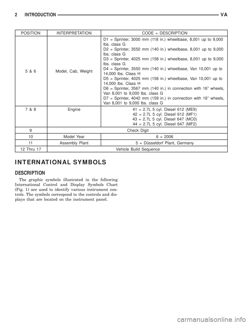
POSITION INTERPRETATION CODE = DESCRIPTION
5 & 6 Model, Cab, WeightD1 = Sprinter, 3000 mm (118 in.) wheelbase, 8,001 up to 9,000
lbs. class G
D2 = Sprinter, 3550 mm (140 in.) wheelbase, 8,001 up to 9,000
lbs. class G
D3 = Sprinter, 4025 mm (158 in.) wheelbase, 8,001 up to 9,000
lbs. class G
D4 = Sprinter, 3550 mm (140 in.) wheelbase, Van 10,001 up to
14,000 lbs. Class H
D5 = Sprinter, 4025 mm (158 in.) wheelbase, Van 10,001 up to
14,000 lbs. Class H
D6 = Sprinter, 3567 mm (140 in.) in connection with 16º wheels,
Van 8,001 to 9,000 lbs. class G
D7 = Sprinter, 4042 mm (159 in.) in connection with 16º wheels,
Van 8,001 to 9,000 lbs. class G
7 & 8 Engine 41 = 2.7L 5 cyl. Diesel 612 (ME9)
42 = 2.7L 5 cyl. Diesel 612 (MF1)
43 = 2.7L 5 cyl. Diesel 647 (MC0)
44 = 2.7L 5 cyl. Diesel 647 (MF2)
9 Check Digit
10 Model Year 6 = 2006
11 Assembly Plant 5 = Dîsseldorf Plant, Germany
12 Thru 17 Vehicle Build Sequence
INTERNATIONAL SYMBOLS
DESCRIPTION
The graphic symbols illustrated in the following
International Control and Display Symbols Chart
(Fig. 1) are used to identify various instrument con-
trols. The symbols correspond to the controls and dis-
plays that are located on the instrument panel.
2 INTRODUCTIONVA
Page 850 of 2305
AUDIO / VIDEO
TABLE OF CONTENTS
page page
AUDIO
SPECIAL TOOLS
AUDIO...............................1
ANTENNA BODY & CABLE
REMOVAL.............................1
INSTALLATION..........................1
INSTRUMENT PANEL ANTENNA CABLE
REMOVAL.............................2INSTALLATION..........................2
RADIO
REMOVAL.............................2
INSTALLATION..........................2
SPEAKER
REMOVAL.............................2
INSTALLATION..........................3
AUDIO
SPECIAL TOOLS
AUDIO
SPECIAL TOOL CROSS REFERENCE CHART
MB
TOOL #MILLER
TOOL #DESCRIPTION
000 589
88 63 009241 RADIO EXTRACTION
TOOL
ANTENNA BODY & CABLE
REMOVAL
(1) Disconnect and isolate the battery negative
cable.
(2) Remove the portion of the headliner over the
front seat passengers (Refer to 23 - BODY/INTERI-
OR/HEADLINER - REMOVAL).
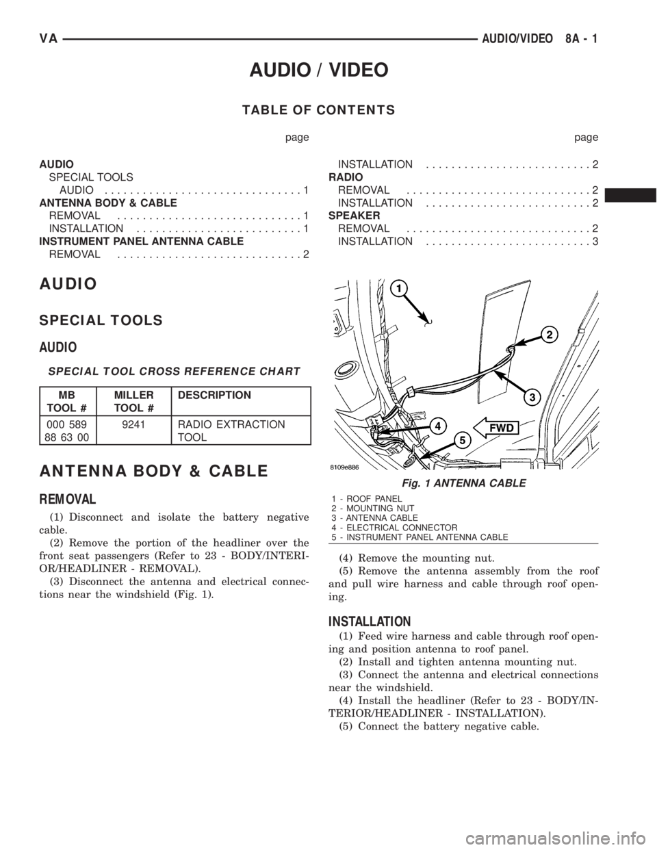
(3) Disconnect the antenna and electrical connec-
tions near the windshield (Fig. 1).(4) Remove the mounting nut.
(5) Remove the antenna assembly from the roof
and pull wire harness and cable through roof open-
ing.
INSTALLATION
(1) Feed wire harness and cable through roof open-
ing and position antenna to roof panel.
(2) Install and tighten antenna mounting nut.
(3) Connect the antenna and electrical connections
near the windshield.
(4) Install the headliner (Refer to 23 - BODY/IN-
TERIOR/HEADLINER - INSTALLATION).
(5) Connect the battery negative cable.
Fig. 1 ANTENNA CABLE
1 - ROOF PANEL
2 - MOUNTING NUT
3 - ANTENNA CABLE
4 - ELECTRICAL CONNECTOR
5 - INSTRUMENT PANEL ANTENNA CABLE
VAAUDIO/VIDEO 8A - 1
Page 851 of 2305
INSTRUMENT PANEL
ANTENNA CABLE
REMOVAL
(1) Disconnect and isolate the battery negative
cable.
(2) Remove the A-pillar trim (Refer to 23 - BODY/
INTERIOR/A-PILLAR TRIM - REMOVAL).
(3) Remove the portion of the headliner over the
front seat passengers (Refer to 23 - BODY/INTERI-
OR/HEADLINER - REMOVAL).
(4) Disconnect the antenna and electrical connec-
tions near the windshield.
(5) Remove the glove box (Refer to 23 - BODY/IN-
STRUMENT PANEL/GLOVE BOX - REMOVAL).
(6) Remove the radio (Refer to 8 - ELECTRICAL/
AUDIO/RADIO - REMOVAL).
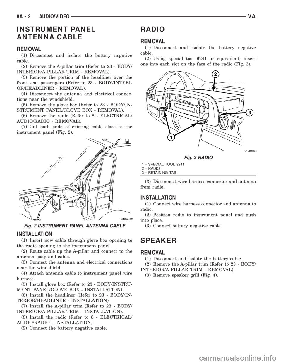
(7) Cut both ends of existing cable close to the
instrument panel (Fig. 2).
INSTALLATION
(1) Insert new cable through glove box opening to
the radio opening in the instrument panel.
(2) Route cable up the A-pillar and connect to the
antenna body and cable.
(3) Connect the antenna and electrical connections
near the windshield.
(4) Attach antenna cable to instrument panel wire
harness.
(5) Install glove box (Refer to 23 - BODY/INSTRU-
MENT PANEL/GLOVE BOX - INSTALLATION).
(6) Install the headliner (Refer to 23 - BODY/IN-
TERIOR/HEADLINER - INSTALLATION).
(7) Install the A-pillar trim (Refer to 23 - BODY/
INTERIOR/A-PILLAR TRIM - INSTALLATION).
(8) Install the radio (Refer to 8 - ELECTRICAL/
AUDIO/RADIO - INSTALLATION).
(9) Connect the battery negative cable.
RADIO
REMOVAL
(1) Disconnect and isolate the battery negative
cable.
(2) Using special tool 9241 or equivalent, insert
one into each slot on the face of the radio (Fig. 3).
(3) Disconnect wire harness connector and antenna
from radio.
INSTALLATION
(1) Connect wire harness connector and antenna to
radio.
(2) Position radio to instrument panel and push
into place.
(3) Connect battery negative cable.
SPEAKER
REMOVAL
(1) Disconnect and isolate the battery cable.
(2) Remove the A-pillar trim (Refer to 23 - BODY/
INTERIOR/A-PILLAR TRIM - REMOVAL).
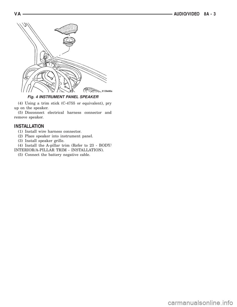
(3) Remove speaker grill (Fig. 4).
Fig. 2 INSTRUMENT PANEL ANTENNA CABLE
Fig. 3 RADIO
1 - SPECIAL TOOL 9241
2 - RADIO
3 - RETAINING TAB
8A - 2 AUDIO/VIDEOVA
Page 852 of 2305
(4) Using a trim stick (C-4755 or equivalent), pry
up on the speaker.
(5) Disconnect electrical harness connector and
remove speaker.
INSTALLATION
(1) Install wire harness connector.
(2) Place speaker into instrument panel.
(3) Install speaker grille.
(4) Install the A-pillar trim (Refer to 23 - BODY/
INTERIOR/A-PILLAR TRIM - INSTALLATION).
(5) Connect the battery negative cable.
Fig. 4 INSTRUMENT PANEL SPEAKER
VAAUDIO/VIDEO 8A - 3
Page 855 of 2305
the status of the driver side front seat belt. This
audible warning occurs independent of the visual
warning provided by the EMIC ªSeatbeltº indicator.
²Lights-On Warning- The EMIC chime tone
generator will generate repetitive chime tones at a
fast rate when either front door is opened with the
ignition switch in any position except On, and the
exterior lights are turned On. The EMIC uses inter-
nal programming and hard wired inputs from the left
(lighting) control stalk of the multi-function switch,
the ignition switch, and both front door jamb
switches to determine the current status of these
switches. This chime will continue to sound until the
exterior lighting is turned Off, until the ignition
switch is turned to the On position, or until both
front doors are closed, whichever occurs first.
²Key-In-Ignition Warning- The EMIC chime
tone generator will generate repetitive chime tones at
a fast rate when the key is in the ignition lock cylin-
der, the ignition switch is in any position except On,
and either front door is opened. The EMIC uses
internal programming and hard wired inputs from
the key-in ignition switch, the ignition switch, and
both front door jamb switches to determine the cur-
rent status of these switches. The chime will con-
tinue to sound until the key is removed from the
ignition lock cylinder, until the ignition switch is
turned to the On position, or until both front doors
are closed, whichever occurs first.
²Audible Turn Signal/Hazard Warning Sup-
port- The EMIC contactless relay will generate
repetitive clicks at a slow rate during normal turn
signal/hazard warning operation, or at a fast rate
when a turn signal lamp bulb or circuit is inopera-
tive, in concert with the operation of the turn signal
indicators in the cluster. These clicks are designed to
emulate the sound of the opening and closing of the
contact points in a conventional electromechanical
turn signal or hazard warning flasher. The EMIC
uses a hard wired input received from the turn sig-
nal relay in the fuse block beneath the steering col-
umn through the turn signal or hazard warning
switch circuitry of the multi-function switch to deter-
mine when to flash the turn signal indicators and
activate the contactless relay on the cluster electronic
circuit board. The turn signal clicks will continue to
sound until the turn signal switch is turned Off, or
until the ignition switch is turned to the Off position,
whichever occurs first. The hazard warning clicks
will continue to sound until the hazard warning
switch is turned Off.
The EMIC provides chime service for all available
features in the chime warning system. The EMIC relies
upon its internal programming and hard wired inputs
from the front door ajar switches, the key-in ignition
switch, the ignition switch, the seat belt switch, and the
turn signal/hazard warning (multi-function) switches.
The EMIC relies upon electronic message inputsreceived from other electronic modules over the CAN
data bus network to provide chime service for the low
engine oil level warning. Upon receiving the proper
inputs, the EMIC activates the chime tone generator or
the contactless relay to provide the audible warning to
the vehicle operator. The internal programming of the
EMIC determines the priority of each chime request
input that is received, as well as the rate and duration
of each tone that is to be generated. See the owner's
manual in the vehicle glove box for more information on
the features provided by the chime warning system.
The hard wired chime warning system inputs to
the EMIC, as well as other hard wired circuits for
this system may be diagnosed and tested using con-
ventional diagnostic tools and procedures. However,
conventional diagnostic methods may not prove con-
clusive in the diagnosis of the EMIC, the CAN data
bus network, or the electronic message inputs used
by the EMIC to provide chime warning system ser-
vice. The most reliable, efficient, and accurate means
to diagnose the EMIC, the CAN data bus network,
and the electronic message inputs for the chime
warning system requires the use of a diagnostic scan
tool. Refer to the appropriate diagnostic information.
DIAGNOSIS AND TESTING - CHIME WARNING
SYSTEM
WARNING: To avoid personal injury or death, on
vehicles equipped with airbags, disable the supple-
mental restraint system before attempting any
steering wheel, steering column, airbag, seat belt
tensioner, or instrument panel component diagno-
sis or service. Disconnect and isolate the battery
negative (ground) cable, then wait two minutes for
the system capacitor to discharge before perform-
ing further diagnosis or service. This is the only
sure way to disable the supplemental restraint sys-
tem. Failure to take the proper precautions could
result in accidental airbag deployment.
The hard wired chime warning system inputs to
the ElectroMechanical Instrument Cluster (EMIC),
as well as other hard wired circuits for this system
may be diagnosed and tested using conventional
diagnostic tools and procedures. However, conven-
tional diagnostic methods may not prove conclusive
in the diagnosis of the EMIC, the Controller Area
Network (CAN) data bus network, or the electronic
message inputs used by the EMIC to provide chime
warning system service. The most reliable, efficient,
and accurate means to diagnose the EMIC, the CAN
data bus network, and the electronic message inputs
for the chime warning system requires the use of a
diagnostic scan tool. Refer to the appropriate diag-
nostic information.
8B - 2 CHIME/BUZZERVA
Page 857 of 2305
actuators.These outputs allow the CTM the ability to
control numerous accessory systems in the vehicle.
The CTM monitors its own internal circuitry as
well as many of its input and output circuits, and
will store a Diagnostic Trouble Code (DTC) in elec-
tronic memory for any failure it detects. These DTCs
can be retrieved and diagnosed using a DRBIIItscan
tool. Refer to the appropriate diagnostic information.
HARD WIRED INPUTS
The hard wired inputs to the CTM include the fol-
lowing:
²Fused B(+)
²Fused ignition switch output (run-acc)
²Fused ignition switch output (run-start)
²Ground
²Key-in ignition switch sense
²Sliding door switch sense
²Passenger door switch sense
²Driver door switch sense
²PCI bus circuit
HARD WIRED OUTPUTS
The hard wired outputs of the CTM include the fol-
lowing:
²Door lock relay output
²Door unlock relay output
²VTSS indicator driver
MESSAGING
The CTM uses the following messages received
from other electronic modules over the PCI data bus:
²Airbag Deploy (ACM)
²Beep request (CMTC)
²Charging System Failure (PCM)
²Chime request (EMIC)
²Engine RPM (PCM)
²OK to Arm VTSS (PCM)
²Security indicator request (SKIM)
²System Voltage (PCM)
²Valid/Invalid Key (SKIM)
²Vehicle Distance (PCM)
²Vehicle Speed (PCM)
DIAGNOSIS AND TESTING - CENTRAL TIMER
MODULE
WARNING: To avoid personal injury or death, on
vehicles equipped with airbags, disable the supple-
mental restraint system before attempting any
steering wheel, steering column, airbag, seat belt
tensioner, or instrument panel component diagno-
sis or service. Disconnect and isolate the battery
negative (ground) cable, then wait two minutes for
the system capacitor to discharge before perform-
ing further diagnosis or service. This is the only
sure way to disable the supplemental restraint sys-tem. Failure to take the proper precautions could
result in accidental airbag deployment.
The hard wired inputs to and outputs from the
central timer module (CTM) may be diagnosed and
tested using conventional diagnostic tools and meth-
ods. Refer to the appropriate wiring information.
However, conventional diagnostic methods may not
prove conclusive in the diagnosis of the CTM. In
order to obtain conclusive testing of the CTM, the
programmable communications interface (PCI) data
bus network and all of the modules that provide
inputs to or receive outputs from the CTM must also
be checked. The most reliable, efficient, and accurate
means to diagnose the CTM, the PCI data bus net-
work, and the modules that provide inputs to, or
receive outputs from, the CTM requires the use of a
DRBIIItscan tool. Refer to the appropriate diagnos-
tic information.
REMOVAL
(1) Disconnect and isolate the battery negative
cable.
(2) Slide the driver seat to the full forward posi-
tion.
(3) Disconnect the wire harness connector for the
seat belt latch. (Fig. 1).
(4) Remove the screws that secure the closeout
panel beneathe the driver seat cushion and remove
the panel.
(5) Remove the screws that secure the central
timer module to the bracket.
(6) Disconnect the wire harness connectors from
the central timer module.
(7) Remove the central timer module from the
vehicle.
8E - 2 ELECTRONIC CONTROL MODULESVA