MERCEDES-BENZ SPRINTER 2014 MY14 Operator’s Manual
Manufacturer: MERCEDES-BENZ, Model Year: 2014, Model line: SPRINTER, Model: MERCEDES-BENZ SPRINTER 2014Pages: 338, PDF Size: 6.78 MB
Page 311 of 338
X
Take the vehicle tool kit and the jack from
the footwell on the co-driver's side
(Y page 276).
X Remove the spare wheel from the spare
wheel bracket (Y page 314). Observe the
safety notes in the "Spare wheel" section
(Y page 313).
X On wheels with wheel bolts, remove the
hub caps. X
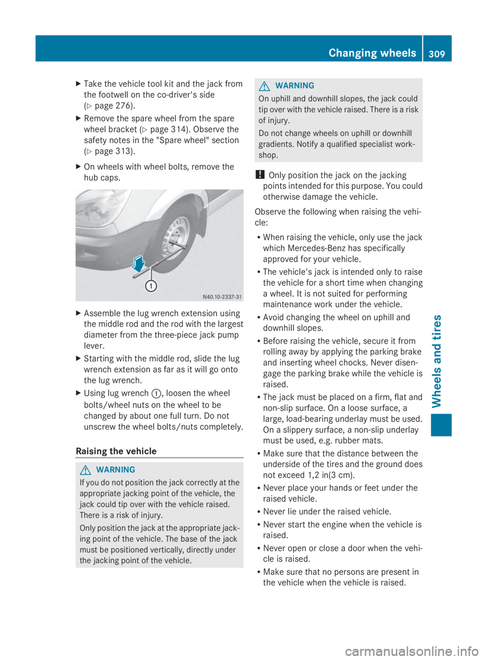
Assemble the lug wrench extension using
the middle rod and the rod with the largest
diameter from the three-piece jack pump
lever.
X Starting with the middle rod, slide the lug
wrench extension as far as it will go onto
the lug wrench.
X Using lug wrench 0043, loosen the wheel
bolts/wheel nuts on the wheel to be
changed by about one full turn. Do not
unscrew the wheel bolts/nuts completely.
Raising the vehicle G
WARNING
If you do not position the jack correctly at the
appropriate jacking point of the vehicle, the
jack could tip over with the vehicle raised.
There is a risk of injury.
Only position the jack at the appropriate jack-
ing point of the vehicle. The base of the jack
must be positioned vertically, directly under
the jacking point of the vehicle. G
WARNING
On uphill and downhill slopes, the jack could
tip over with the vehicle raised. There is a risk
of injury.
Do not change wheels on uphill or downhill
gradients. Notify a qualified specialist work-
shop.
! Only position the jack on the jacking
points intended for this purpose. You could
otherwise damage the vehicle.
Observe the following when raising the vehi-
cle:
R When raising the vehicle, only use the jack
which Mercedes-Benz has specifically
approved for your vehicle.
R The vehicle's jack is intended only to raise
the vehicle for a short time when changing
a wheel. It is not suited for performing
maintenance work under the vehicle.
R Avoid changing the wheel on uphill and
downhill slopes.
R Before raising the vehicle, secure it from
rolling away by applying the parking brake
and inserting wheel chocks. Never disen-
gage the parking brake while the vehicle is
raised.
R The jack must be placed on a firm, flat and
non-slip surface. On a loose surface, a
large, load-bearing underlay must be used.
On a slippery surface, a non-slip underlay
must be used, e.g. rubber mats.
R Make sure that the distance between the
underside of the tires and the ground does
not exceed 1,2 in(3 cm).
R Never place your hands or feet under the
raised vehicle.
R Never lie under the raised vehicle.
R Never start the engine when the vehicle is
raised.
R Never open or close a door when the vehi-
cle is raised.
R Make sure that no persons are present in
the vehicle when the vehicle is raised. Changing wheels
309Wheels and tires Z
Page 312 of 338
!
Only use the jack pump lever middle rod
and the rod with the largest diameter as a
lug wrench extension. Only slide the middle
rod as far as it will go onto the lug wrench.
The rods may otherwise bend and be dis-
torted to such an extent that they can no
longer be used as a pump lever for the jack.
! Do not place the jack on the leaf spring or
the differential case. Hydraulic jack
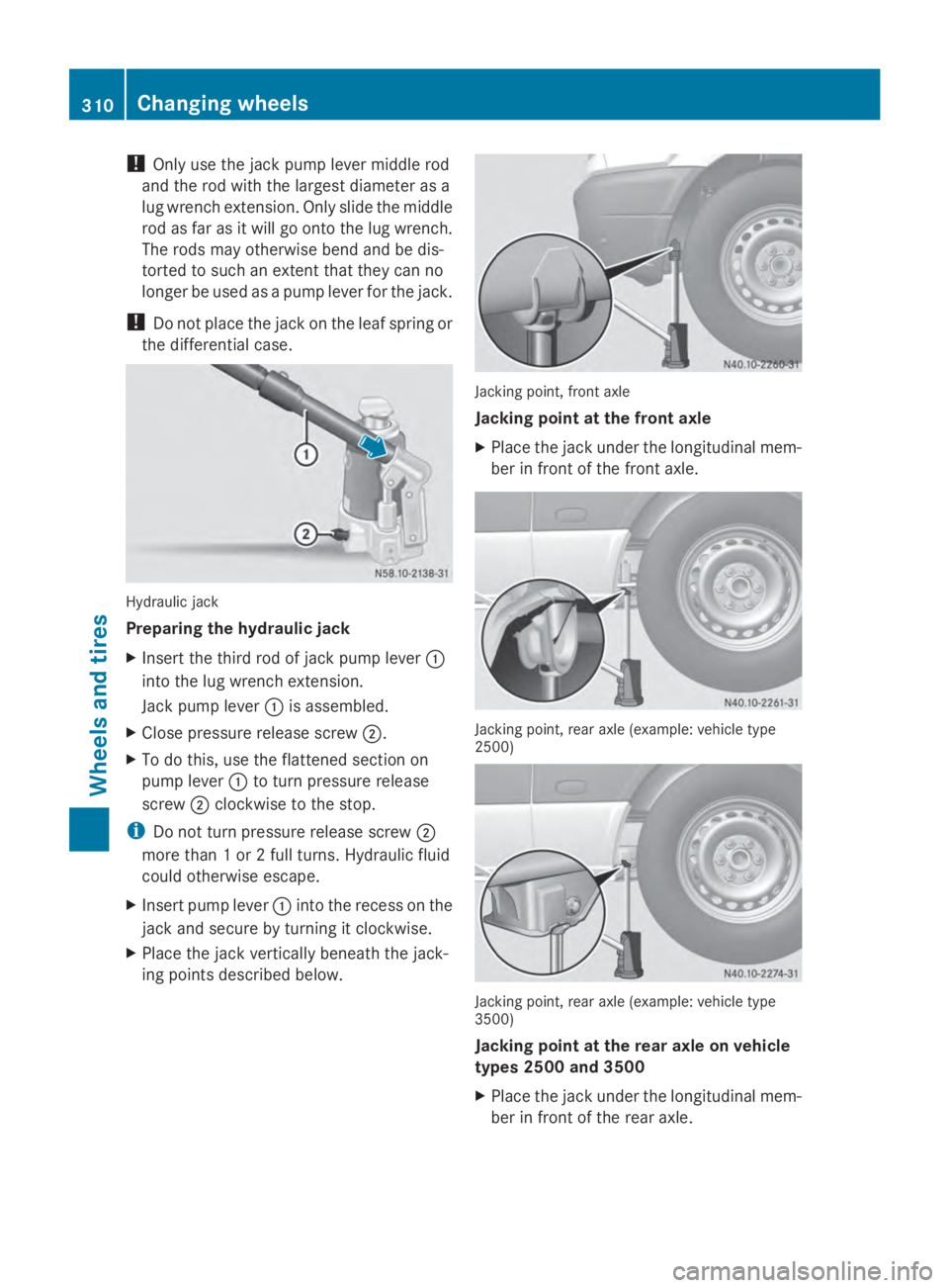
Preparing the hydraulic jack
X
Insert the third rod of jack pump lever 0043
into the lug wrench extension.
Jack pump lever 0043is assembled.
X Close pressure release screw 0044.
X To do this, use the flattened section on
pump lever 0043to turn pressure release
screw 0044clockwise to the stop.
i Do not turn pressure release screw 0044
more than 1 or 2 full turns. Hydraulic fluid
could otherwise escape.
X Insert pump lever 0043into the recess on the
jack and secure by turning it clockwise.
X Place the jack vertically beneath the jack-
ing points described below. Jacking point, front axle
Jacking point at the front axle
X
Place the jack under the longitudinal mem-
ber in front of the front axle. Jacking point, rear axle (example: vehicle type
2500)
Jacking point, rear axle (example: vehicle type
3500)
Jacking point at the rear axle on vehicle
types 2500 and 3500
X Place the jack under the longitudinal mem-
ber in front of the rear axle. 310
Changing wheelsWheels and tires
Page 313 of 338
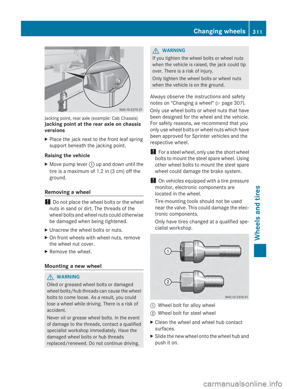
Jacking point, rear axle (example: Cab Chassis)
Jacking point at the rear axle on chassis
versions
X Place the jack next to the front leaf spring
support beneath the jacking point.
Raising the vehicle
X Move pump lever 0043up and down until the
tire is a maximum of 1.2 in (3 cm) off the
ground.
Removing a wheel !
Do not place the wheel bolts or the wheel
nuts in sand or dirt. The threads of the
wheel bolts and wheel nuts could otherwise
be damaged when being tightened.
X Unscrew the wheel bolts or nuts.
X On front wheels with wheel nuts, remove
the wheel nut cover.
X Remove the wheel.
Mounting a new wheel G
WARNING
Oiled or greased wheel bolts or damaged
wheel bolts/hub threads can cause the wheel
bolts to come loose. As a result, you could
lose a wheel while driving. There is a risk of
accident.
Never oil or grease wheel bolts. In the event
of damage to the threads, contact a qualified
specialist workshop immediately. Have the
damaged wheel bolts or hub threads
replaced/renewed. Do not continue driving. G
WARNING
If you tighten the wheel bolts or wheel nuts
when the vehicle is raised, the jack could tip
over. There is a risk of injury.
Only tighten the wheel bolts or wheel nuts
when the vehicle is on the ground.
Always observe the instructions and safety
notes on "Changing a wheel" ( Ypage 307).
Only use wheel bolts or wheel nuts that have
been designed for the wheel and the vehicle.
For safety reasons, we recommend that you
only use wheel bolts or wheel nuts which have
been approved for Sprinter vehicles and the
respective wheel.
! For a steel wheel, only use the short wheel
bolts to mount the steel spare wheel. Using
other wheel bolts to mount the steel spare
wheel could damage the brake system.
! On vehicles equipped with a tire pressure
monitor, electronic components are
located in the wheel.
Tire-mounting tools should not be used
near the valve. This could damage the elec-
tronic components.
Only have tires changed at a qualified spe-
cialist workshop. 0043
Wheel bolt for alloy wheel
0044 Wheel bolt for steel wheel
X Clean the wheel and wheel hub contact
surfaces.
X Slide the new wheel onto the wheel hub and
push it on. Changing wheels
311Wheels and tires Z
Page 314 of 338
Wheels with centering by wheel bolts:
X
Vehicles with alloy wheels: take the short
wheel bolts that fit the steel spare wheel
out of the vehicle tool kit.
X Screw in the wheel bolts and tighten them
lightly.
For wheels with wheel nuts:
X Front wheels with wheel nut covers: press
the wheel nut covers onto the wheel nuts.
X Screw in the three wheel nuts over the fix-
ing discs of the wheel nut cover.
X Turn the wheel so that the wheel bolts are
in the middle of the holes.
X Screw on the rest of the wheel nuts.
X Slightly tighten all the wheel nuts.
Lowering the vehicle G
WARNING
The wheels could work loose if the wheel nuts
and bolts are not tightened to the specified
tightening torque. There is a risk of accident.
Have the tightening torque immediately
checked at a qualified specialist workshop
after a wheel is changed.
! Only use the jack pump lever middle rod
and the rod with the largest diameter as a
lug wrench extension. Only slide the middle
rod as far as it will go onto the lug wrench.
The rods may otherwise bend and be dis-
torted to such an extent that they can no
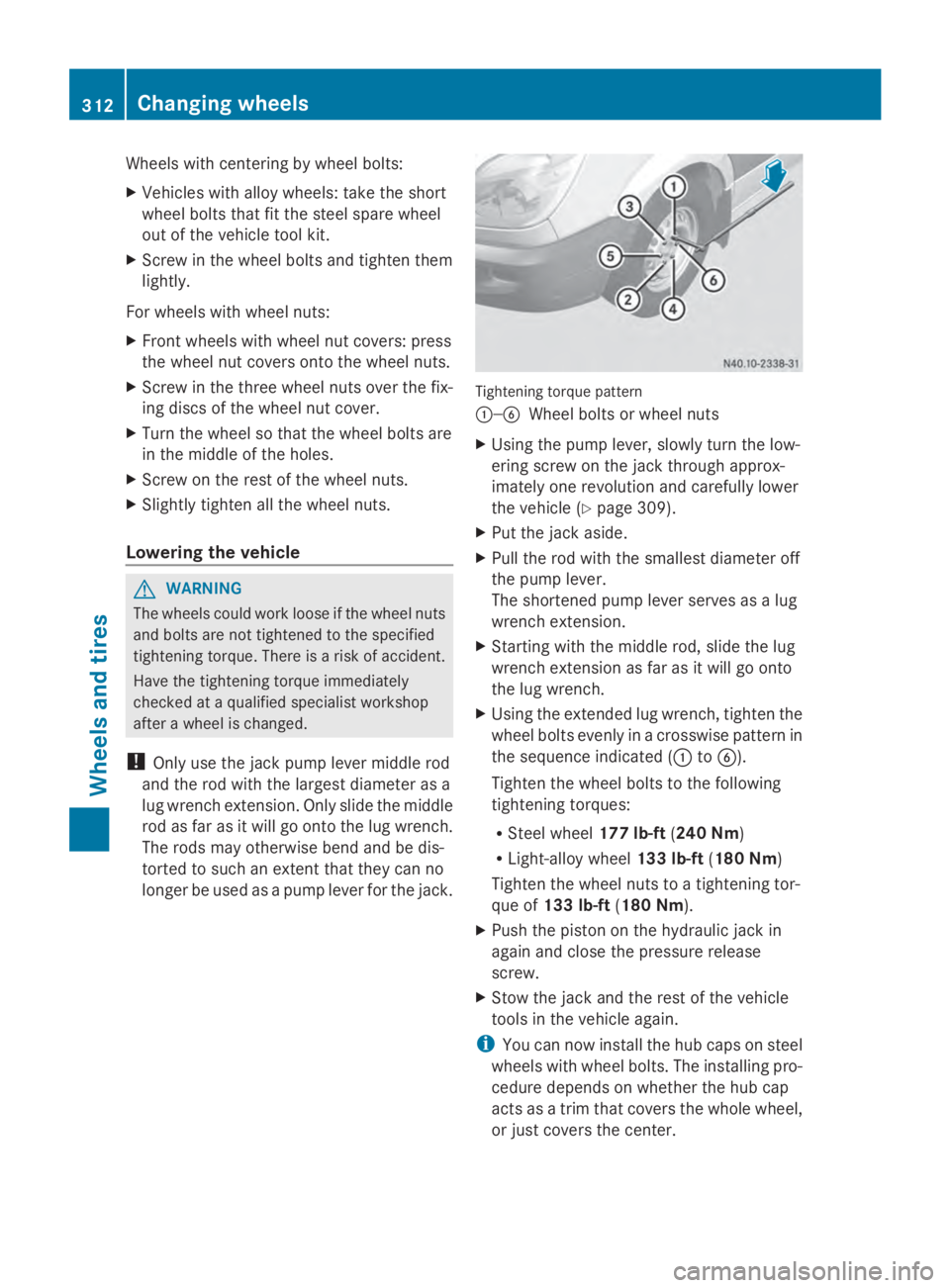
longer be used as a pump lever for the jack. Tightening torque pattern
0043—0084
Wheel bolts or wheel nuts
X Using the pump lever, slowly turn the low-
ering screw on the jack through approx-
imately one revolution and carefully lower
the vehicle (Y page 309).
X Put the jack aside.
X Pull the rod with the smallest diameter off
the pump lever.
The shortened pump lever serves as a lug
wrench extension.
X Starting with the middle rod, slide the lug
wrench extension as far as it will go onto
the lug wrench.
X Using the extended lug wrench, tighten the
wheel bolts evenly in a crosswise pattern in
the sequence indicated (0043 to0084).
Tighten the wheel bolts to the following
tightening torques:
R Steel wheel 177 lb-ft(240 Nm)
R Light-alloy wheel 133 lb-ft(180 Nm)
Tighten the wheel nuts to a tightening tor-
que of 133 lb-ft (180 Nm).
X Push the piston on the hydraulic jack in
again and close the pressure release
screw.
X Stow the jack and the rest of the vehicle
tools in the vehicle again.
i You can now install the hub caps on steel
wheels with wheel bolts. The installing pro-
cedure depends on whether the hub cap
acts as a trim that covers the whole wheel,
or just covers the center. 312
Changing wheelsWheels and tires
Page 315 of 338
X
Wheel with hub cap: position the opening
for the tire valve in the hub cap over the tire
valve.
X Push the edge of the hub cap with both
hands against the wheel until it clicks into
place. Make sure the hub cap retaining
catches engage on the steel wheel.
X Wheel with central hub cap: position the
retaining lugs of the central hub cap over
the wheel bolts.
X Hit the middle of the hub cap to engage it
on the wheel.
X Secure the faulty wheel in the spare wheel
bracket (Y page 314).
X Check the tire pressure of the newly
mounted wheel and adjust it if necessary.
Observe the recommended tire pressure
(Y page 290).
X Retighten the wheel bolts or wheel nuts to
the specified tightening torque after the
vehicle has been driven for 30 miles
(50 km).
When using a wheel/spare wheel with a new
or newly painted wheel rim, have the wheel
bolts/nuts retightened again after approx-
imately 600 to 3,000 miles (1,000 to
5,000 km). Observe the specified tightening
torque.
i Vehicles with the tire pressure monitor
system: all mounted wheels must be equip-
ped with functioning sensors. Wheel and tire combination
General notes
! Retreaded tires are neither tested nor rec-
ommended for Sprinter vehicles, since pre-
vious damage cannot always be detected
on retreaded tires. We can therefore not
guarantee driving safety. Do not mount
used tires if you have no information about
their previous usage. The recommended tire pressures can be
found:
R
on the Tire and Loading Information plac-
ard 8
on the B-pillar on the driver's side
R on the tire pressure table on the B-pillar on
the driver's side
The recommended tire pressure can also be
found in the "Tire pressure table" section in
these Operating Instructions (Y page 297).
The wheel/tire combination for your vehicle
can be found on the tire pressure table. Fur-
ther information on wheel/tire combination
can be obtained at any qualified specialist
workshop.
Check tire pressures regularly and only when
the tires are cold. Observe the notes on the
recommended tire pressures (Y page 290).
Follow the maintenance recommendations in
the tire manufacturer's warranty book in your
vehicle documents.
Notes on the vehicle equipment – always
install the vehicle:
R with tires of the same size across an axle
(left/right)
R with the same type of tires on all wheels at
a given time (summer tires, winter tires) Spare wheel
Important safety notes
G
WARNING
Wheel and tire dimensions as well as the type
of tire can vary between the spare wheel and
the wheel to be replaced. When the spare
wheel is mounted, driving characteristics may
be severely affected. There is a risk of an acci-
dent.
In order to reduce risks:
R you should therefore adapt your driving
style and drive carefully.
R never mount more than one spare wheel
that differs from the wheel to be replaced.
8 Only for vehicles with a gross weight of less than 10,000 lbs(4,536 kg). Spare wheel
313Wheels and tires
Z
Page 316 of 338
R
only use a spare wheel that differs from the
wheel to be replaced for a short time.
R do not deactivate ESP ®
.
R have a spare wheel that differs from the
wheel that has been changed replaced at
the nearest qualified specialist workshop.
You must observe the correct wheel and
tire dimensions as well as the wheel type.
When using a spare wheel of a different size,
do not exceed the maximum speed of
80 km/h. General notes
! Check the spare wheel regularly to see
that it is secure and has the prescribed tire
pressure.
The procedure for mounting the spare wheel
is described in "Mounting a wheel"
(Y page 308).
The following should be checked regularly,
particularly prior to long journeys:
R the tire pressure of the spare wheel, which
should then be corrected if necessary
(Y page 290).
R the fastenings of the spare wheel bracket.
The spare wheel is located in a spare wheel
bracket under the rear of the vehicle.
Replace the tires after 6 years at the latest,
regardless of wear. This also applies to the
spare wheel.
i If you have mounted a spare wheel, the
tire pressure monitor (Y page 293) will not
function for this wheel. The spare wheel is
not equipped with a sensor for monitoring
tire pressure. Removing and installing the spare
wheel
Cargo Van/Passenger Van Bolt covers for the safety catches (example: Cargo
Van)
Removing
X
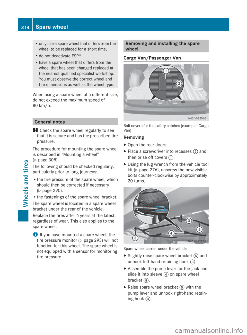
Open the rear doors.
X Place a screwdriver into recesses 0044and
then prise off covers 0043.
X Using the lug wrench from the vehicle tool
kit (Y page 276), unscrew the now visible
bolts counter-clockwise by approximately
20 turns. Spare wheel carrier under the vehicle
X Slightly raise spare wheel bracket 0083and
unhook left-hand retaining hook 0087.
X Assemble the pump lever for the jack and
slide it into sleeve 0085on spare wheel
bracket 0083.
X Raise spare wheel bracket 0083with the
pump lever and unhook right-hand retain-
ing hook 0087. 314
Spare wheelWheels and tires
Page 317 of 338
X
Slowly lower spare wheel bracket 0083down
to the ground.
X Lift spare wheel bracket 0083slightly and pull
the pump lever out of sleeve 0085.Spare wheel in the spare wheel carrier
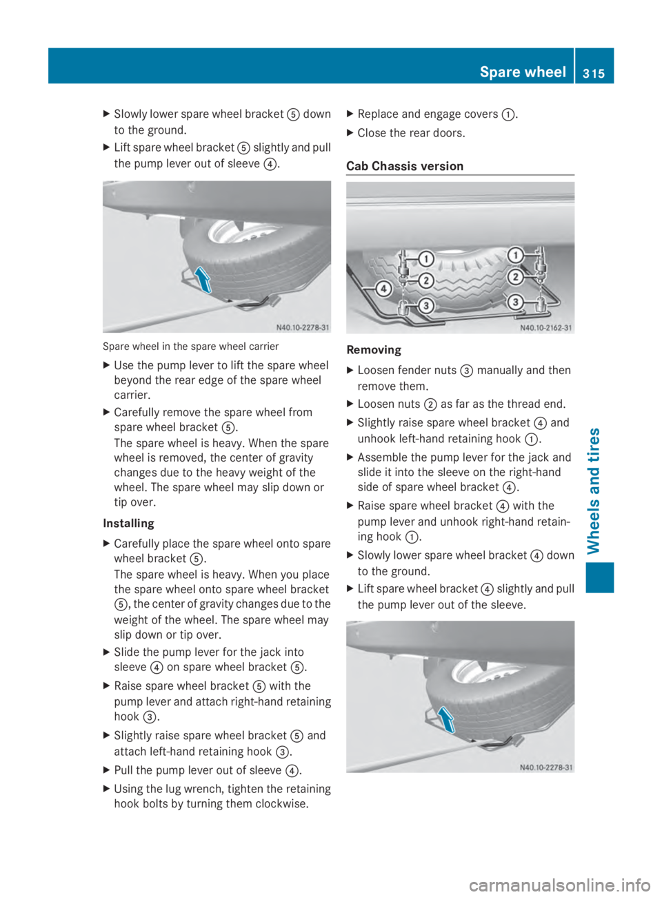
X Use the pump lever to lift the spare wheel
beyond the rear edge of the spare wheel
carrier.
X Carefully remove the spare wheel from
spare wheel bracket 0083.
The spare wheel is heavy. When the spare
wheel is removed, the center of gravity
changes due to the heavy weight of the
wheel. The spare wheel may slip down or
tip over.
Installing
X Carefully place the spare wheel onto spare
wheel bracket 0083.
The spare wheel is heavy. When you place
the spare wheel onto spare wheel bracket
0083, the center of gravity changes due to the
weight of the wheel. The spare wheel may
slip down or tip over.
X Slide the pump lever for the jack into
sleeve 0085on spare wheel bracket 0083.
X Raise spare wheel bracket 0083with the
pump lever and attach right-hand retaining
hook 0087.
X Slightly raise spare wheel bracket 0083and
attach left-hand retaining hook 0087.
X Pull the pump lever out of sleeve 0085.
X Using the lug wrench, tighten the retaining
hook bolts by turning them clockwise. X
Replace and engage covers 0043.
X Close the rear doors.
Cab Chassis version Removing
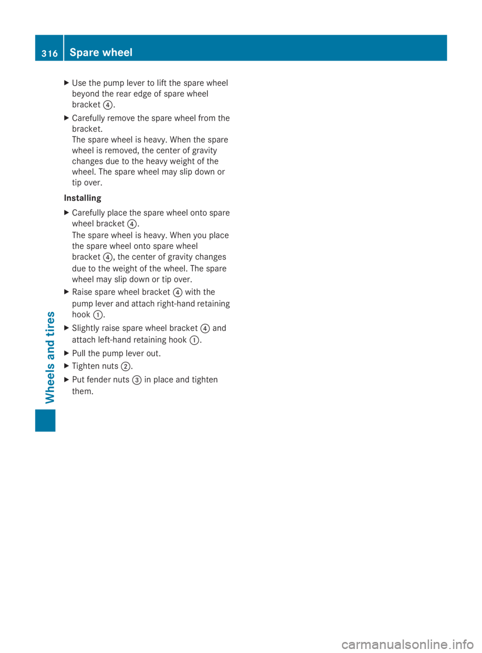
X
Loosen fender nuts 0087manually and then
remove them.
X Loosen nuts 0044as far as the thread end.
X Slightly raise spare wheel bracket 0085and
unhook left-hand retaining hook 0043.
X Assemble the pump lever for the jack and
slide it into the sleeve on the right-hand
side of spare wheel bracket 0085.
X Raise spare wheel bracket 0085with the
pump lever and unhook right-hand retain-
ing hook 0043.
X Slowly lower spare wheel bracket 0085down
to the ground.
X Lift spare wheel bracket 0085slightly and pull
the pump lever out of the sleeve. Spare wheel
315Wheels and tires Z
Page 318 of 338
X
Use the pump lever to lift the spare wheel
beyond the rear edge of spare wheel
bracket 0085.
X Carefully remove the spare wheel from the
bracket.
The spare wheel is heavy. When the spare
wheel is removed, the center of gravity
changes due to the heavy weight of the
wheel. The spare wheel may slip down or
tip over.
Installing
X Carefully place the spare wheel onto spare
wheel bracket 0085.
The spare wheel is heavy. When you place
the spare wheel onto spare wheel
bracket 0085, the center of gravity changes
due to the weight of the wheel. The spare
wheel may slip down or tip over.
X Raise spare wheel bracket 0085with the
pump lever and attach right-hand retaining
hook 0043.
X Slightly raise spare wheel bracket 0085and
attach left-hand retaining hook 0043.
X Pull the pump lever out.
X Tighten nuts 0044.
X Put fender nuts 0087in place and tighten
them. 316
Spare wheelWheels and tires
Page 319 of 338
Genuine Sprinter parts
.....................318
Vehicle electronics ...........................318
Identification plates .........................319
Service products and capacities .....320
Vehicle data ...................................... 331 317Technical data
Page 320 of 338
Genuine Sprinter parts
! Air bags and Emergency Tensioning Devi-
ces, as well as control units and sensors for
these restraint systems, may be installed in
the following areas of your vehicle:
R doors
R door pillars
R door sills
R seats
R cockpit
R instrument cluster
R center console
Do not install accessories such as audio
systems in these areas. Do not carry out
repairs or welding. You could impair the
operating efficiency of the restraint sys-
tems.
Have aftermarket accessories installed at
a qualified specialist workshop. H
Environmental note
We supply reconditioned assemblies and
parts which are of the same quality as new
parts. The same New Vehicle Limited War-
ranty applies as for new parts.
We test genuine Sprinter parts, as well as
conversion parts and accessories that have
been specifically approved for the type of
vehicle, for:
R reliability
R safety
R suitability
Despite ongoing market research, we are
unable to assess other parts. If individual or
official approval is given, we assume no
responsibility for use in Sprinter vehicles.
In some countries, certain parts are only offi-
cially approved for installation or modification
if they comply with legal requirements. All
genuine Sprinter parts satisfy these require-
ments. Make sure that all parts are suitable
for your vehicle. All authorized Sprinter Dealers maintain a
supply of genuine Sprinter parts for required
service and repair work. Also, the strategi-
cally distributed parts delivery centers pro-
vide quick and reliable parts service.
Always specify the vehicle identification num-
ber (VIN) and engine number when ordering
genuine Sprinter parts (Y page 319). Vehicle electronics
Tampering with the engine electron-
ics
G
WARNING
Always have work on the engine electronics
and related components carried out at a quali-
fied specialist workshop. Otherwise, the vehi-
cle's operating safety could be affected.
! Only have engine electronics and the cor-
responding parts, such as control units,
sensors or connector leads, serviced in a
qualified specialist workshop. Otherwise,
the vehicle parts may wear more quickly.
This can lead to loss of the New Vehicle
Limited Warranty. Installing electrical or electronic
equipment
G
WARNING
You and others may damage your health due
to excessive electromagnetic radiation. By
using an external antenna, the possible health
risks of electromagnetic fields, which are
under discussion among the scientific com-
munity, should be largely prevented.
Therefore, only have the exterior antenna
installed at a qualified specialist workshop.
Electrical and electronic devices may have a
detrimental effect on both the comfort and
the operating safety of the vehicle. If equip-
ment of this kind is retrofitted, its electro- 318
Vehicle electronicsTechnical data