air condition MERCEDES-BENZ SPRINTER 2019 MY19 Fuse Allocation Supplement
[x] Cancel search | Manufacturer: MERCEDES-BENZ, Model Year: 2019, Model line: SPRINTER, Model: MERCEDES-BENZ SPRINTER 2019Pages: 20, PDF Size: 0.98 MB
Page 7 of 20

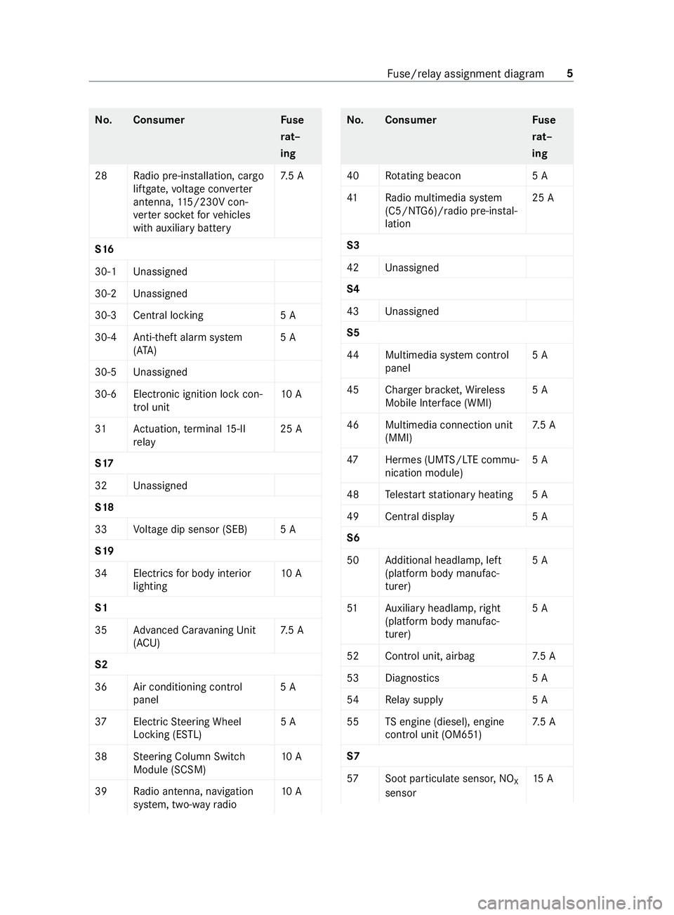
No
.C onsumer Fuse
ra t–
ing
28 Radio pre-ins tallation, cargo
liftgate, voltage con verter
antenna, 115/230V con‐
ve rter soc ketfo rve hicles
with auxiliary battery 7.
5 A
S16
30-1 Unassigned
30-2 Unassigned
30-3 Central locking 5 A
30-4 Anti-theft ala rmsystem
(A TA ) 5 A
30-5 Unassigned
30-6 Electronic ignition lock con‐ trol unit 10 A
31 Actuation, term inal 15-II
re lay 25 A
S17
32 Unassigned
S18
33 Voltage dip sensor (SEB) 5 A
S19
34 Electrics for body interior
lighting 10 A
S1
35 Advanced Ca rava ning Unit
(ACU) 7.
5 A
S2
36 Air conditioning control panel 5 A
37 ElectricSteering Wheel
Locking (ESTL) 5 A
38 Steering Column Switch
Module (SCSM) 10 A
39 Radio antenna, navigation
sy stem, two-w ayradio 10 A No
.C onsumer Fuse
ra t–
ing
40 Rotating beaco n5 A
41 Radio multimedia sy stem
(C5/NTG6)/radio pre-ins tal‐
lation 25 A
S3
42 Unassigned
S4
43 Unassigned
S5
44 Multimedia sy stem cont rol
panel 5 A
45 Charger brac ket,Wi reless
Mobile Inter face (WMI) 5 A
46 Multimedia connection unit (MMI) 7.
5 A
47 Hermes (UMTS/LTE commu‐
nication module) 5 A
48 Teles tart stationary heating 5 A
49 Cent ral displa y5 A
S6
50 Additional headlamp, left
(platform body manufac‐
turer) 5 A
51 Auxilia ryheadlamp ,ri ght
(platform body manufac‐
turer) 5 A
52 Control unit, airbag 7.5 A
53 Diagno stics 5 A
54 Relay suppl y5 A
55 TSengine (diesel), engine
cont rol unit (OM651) 7.
5 A
S7
57 Soot particulate sensor, NO
X
sensor 15 A Fu
se/relay assignment diagram 5
Page 12 of 20

R
from the body manufacturers forre tard ers,
cargo liftgate, hydraulic pump and dumper
ve hicle %
Alw
ays ha vethe fuses/rela ysinthe seat
base replaced at a qualified specialist work‐
shop. Fu
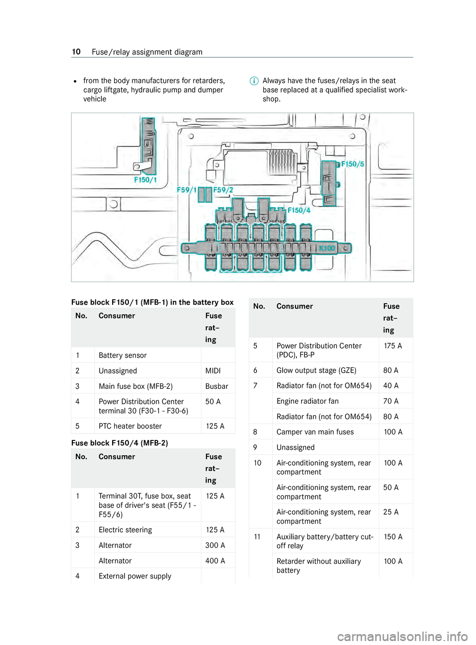
se block F150/1 (MFB-1) in the bat tery box No
.C onsumer Fuse
ra t–
ing
1B attery sensor
2U nassigned MIDI
3M ain fuse box (MFB-2) Busbar
4P ower Distribution Center
te rm inal 30 (F30-1 - F30-6) 50 A
5P TCheater boos ter1 25 A Fu
se block F150/4 (MFB-2) No
.C onsumer Fuse
ra t–
ing
1T erminal 30T, fuse box, seat
base of driver's seat (F55/1 -
F55/6) 12
5 A
2E lectric st eering 125 A
3A lternator 300 A
Alternator 400 A
4E xternal po wer supply No
.C onsumer Fuse
ra t–
ing
5P ower Distribution Center
(PDC), FB-P 17
5 A
6G low output stage (GZE) 80 A
7R adiatorfan (not for OM654) 40 A
Engine radiator fan7 0 A
Ra diator fan (not for OM654) 80 A
8C ampervan main fuses 100 A
9U nassigned
10 Air-conditioning sy stem, rear
compartment 10
0 A
Air-conditioning sy stem, rear
compartment 50 A
Air-conditioning sy stem, rear
compartment 25 A
11 Auxilia rybattery/battery cut‐
off relay 15
0 A
Re tard er without auxiliary
battery 10
0 A 10
Fuse/relay assignment diagram