torque MERCEDES-BENZ SPRINTER 2019 MY19 with 7” screen
[x] Cancel search | Manufacturer: MERCEDES-BENZ, Model Year: 2019, Model line: SPRINTER, Model: MERCEDES-BENZ SPRINTER 2019Pages: 354, PDF Size: 6.15 MB
Page 143 of 354

If it is not possible
toengage all-wheel drive when
th eve hicle is rolling: #
Vehicles with automatic transmission:
brief lymo vethe selector le verto 005C . Engaging/disen
gaging all-wheel drive *
NO
TERisk of damage tothe transfer
case If
yo ustep on the accelerator pedal while the
all-wheel drive is engaged or disen gage d, the
trans fer case may be dama ged. #
Do not step on the accelera tor pedal
when the indicator lamp in the switch
fo rth e all-wheel drive is flashing. #
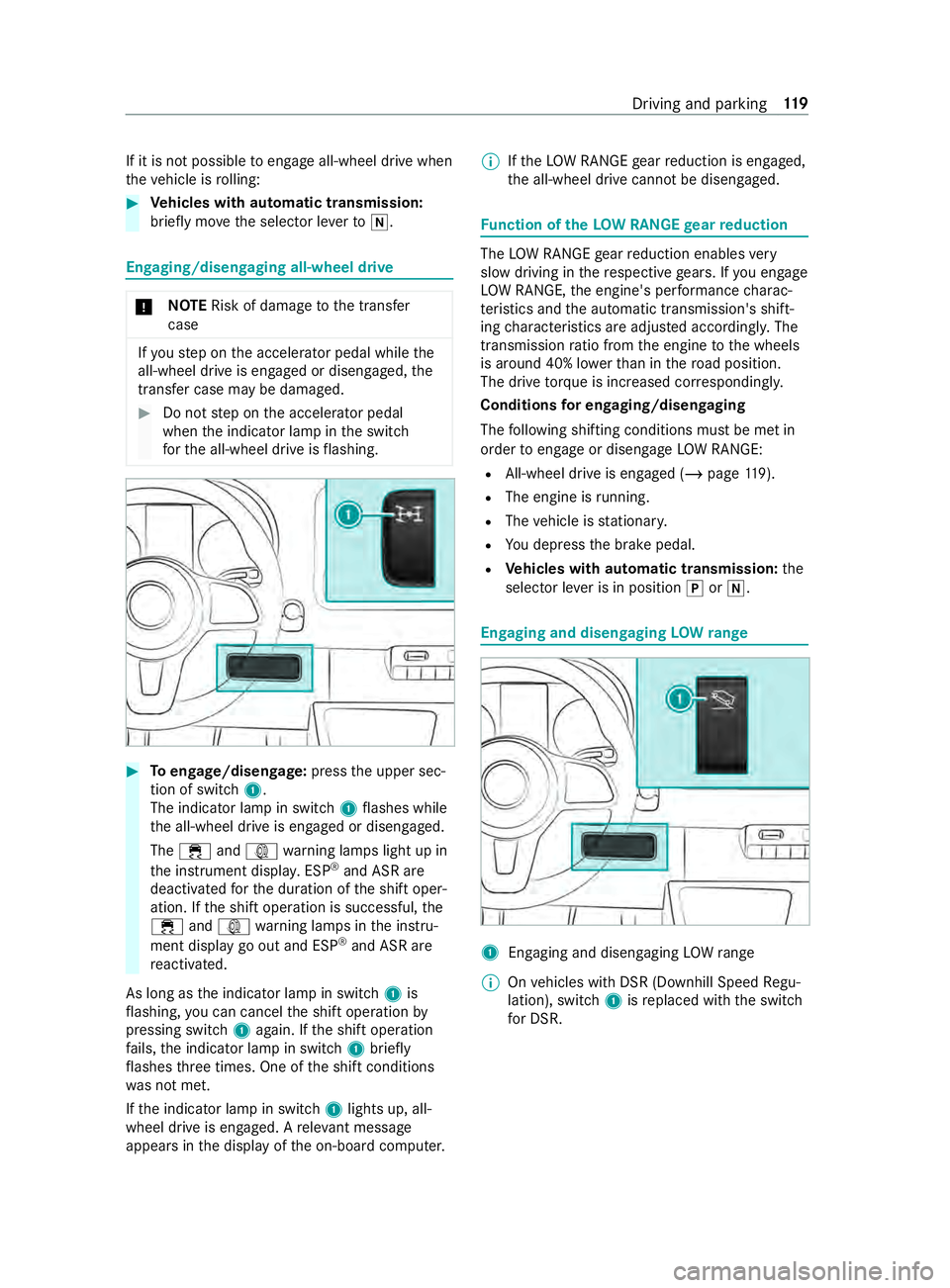
Toengage/disen gage:press the upper sec‐
tion of switch 1.
The indicator lamp in switch 1flashes while
th e all-wheel drive is engaged or disengaged.
The 00E5 and003D warning lamps light up in
th e instrument displa y.ESP ®
and ASR are
deacti vatedfo rth e duration of the shift oper‐
ation. If the shift operation is successful, the
00E5 and003D warning lamps in the instru‐
ment display go out and ESP ®
and ASR are
re activated.
As long as the indicator lamp in switch 1is
fl ashing, you can cancel the shift operation by
pressing switch 1again. If the shift operation
fa ils, the indicator lamp in switch 1brief ly
fl ashes thre e times. One of the shift conditions
wa s not met.
If th e indicator lamp in switch 1lights up, all-
wheel drive is engaged. A releva nt messa ge
appears in the display of the on-board computer. %
If
th eLO W RANGE gear reduction is engaged,
th e all-wheel drive cann otbe disengaged. Fu
nction of theLO W RANGE gear reduction The
LOW RANGE gear reduction enables very
slow driving in there spective gears. If you engage
LO W RANGE, the engine's per form ance charac‐
te rist ics and the automatic transmission's shift‐
ing characteristics are adjus ted according ly. The
transmission ratio from the engine tothe wheels
is around 40% lo werth an in thero ad position.
The drive torque is in creased cor respondingly.
Conditions for en gaging/disengaging
The following shifting conditions must be met in
order toengage or disengage LOW RANGE:
R All-wheel drive is engaged (/ page119).
R The engi ne isrunning.
R The vehicle is stationar y.
R You depress the brake pedal.
R Vehicles with automatic transmission: the
selector le ver is in position 005Dor005C. Engaging and disen
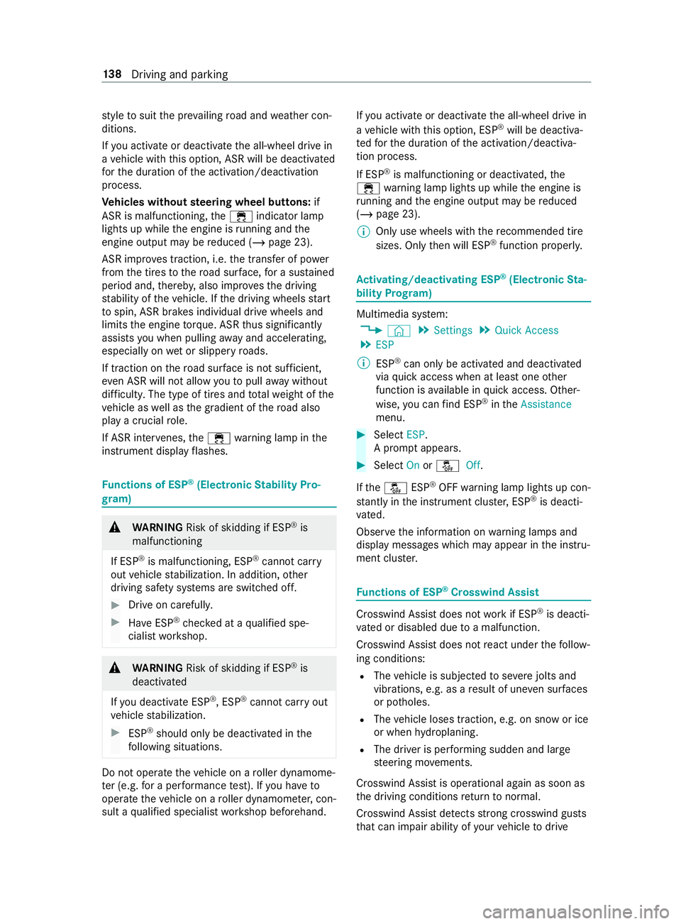
gaging LOW range 1
Enga ging and disengaging LOWrange
% On
vehicles with DSR (Downhill Speed Regu‐
lation), switch 1isreplaced with the switch
fo r DSR. Driving and parking
11 9
Page 162 of 354

st
yle to suit the pr evailing road and weather con‐
ditions.
If yo u activate or deactivate the all-wheel drive in
a ve hicle with this option, ASR will be deactivated
fo rth e duration of the activation/deactivation
process.
Ve hicles without steering wheel but tons: if
ASR is malfunctioning, the00E5 indicator lamp
lights up while the engine is running and the
engine output may be reduced (/ page 23).
ASR impr oves traction, i.e. the transfer of po wer
from the tires tothero ad sur face, for a sus tained
period and, thereb y,also impr ovesth e driving
st ability of theve hicle. If the driving wheels start
to spin, ASR brakes individual drive wheels and
limits the engine torque. ASRthus significantly
assists you when pulling away and accelerating,
especially on wet or slippe ryroads.
If traction on thero ad sur face is not suf ficient,
eve n ASR will not allow youto pull away without
dif ficulty. The type of tires and totalwe ight of the
ve hicle as well as the gradient of thero ad also
play a crucial role.
If ASR inter venes, the00E5 warning lamp in the
instrument display flashes. Fu
nctions of ESP ®
(Electronic Stability Pro‐
gr am) &
WARNING Risk of skidding if ESP ®
is
malfunctioning
If ESP ®
is malfunctioning, ESP ®
cannot car ry
out vehicle stabilization. In addition, other
driving saf ety sy stems are switched off. #
Drive on carefull y. #
Have ESP ®
ch ecked at a qualified spe‐
cialist workshop. &
WARNING Risk of skidding if ESP ®
is
deactivated
If yo u deactivate ESP ®
, ESP ®
cannot car ryout
ve hicle stabilization. #
ESP ®
should only be deactivated in the
fo llowing situations. Do not opera
tetheve hicle on a roller dynamome‐
te r (e.g. for a per form ance test). If you ha veto
operate theve hicle on a roller dynamom eter, con‐
sult a qualified specialist workshop beforehand. If
yo u activate or deactivate the all-wheel drive in
a ve hicle with this option, ESP ®
will be deactiva‐
te dfo rth e duration of the activation/deactiva‐
tion process.
If ESP ®
is malfunctioning or deactivated, the
00E5 warning lamp lights up while the engine is
ru nning and the engine output may be reduced
(/ page 23).
% Only use wheels with
there commended tire
sizes. Only then will ESP ®
function properly. Ac
tivating/deactivating ESP ®
(Electronic Sta‐
bility Prog ram) Multimedia sy
stem:
4 © 5
Settings 5
Quick Access
5 ESP
% ESP®
can only be activated and deactivated
via quick access when at least one other
function is available in quick access. Other‐
wise, you can find ESP ®
in theAssistance
menu. #
Select ESP.
A prom ptappears. #
Select Onor00BB Off.
If th e00BB ESP®
OFF warning lamp lights up con‐
st antly in the instrument clus ter,ESP ®
is deacti‐
va ted.
Obser vethe information on warning lamps and
display messages which may appear in the instru‐
ment clus ter. Fu
nctions of ESP ®
Crosswind Assist Crosswind Assist does not
workif ESP ®
is deacti‐
va ted or disabled due toa malfunction.
Crosswind Assist does not react under thefo llow‐
ing conditions:
R The vehicle is subjected tosevere jolts and
vib rations, e.g. as a result of une ven su rfaces
or po tholes.
R The vehicle loses traction, e.g. on snow or ice
or when hydroplaning.
R The driver is per form ing sudden and lar ge
st eering mo vements.
Crosswind Assist is operational again as soon as
th e driving conditions return tonormal.
Crosswind Assi stdetects stro ng crosswind gu sts
th at can impair ability of your vehicle todrive 13 8
Driving and pa rking
Page 278 of 354

&
WARNING Risk of inju ryfrom tightening
wheel bolts and nuts
If yo u tighten the wheel bolts or wheel nuts
when theve hicle is raised, the jack could tip. #
Only tighten wheel bolts or wheel nuts
when theve hicle is on the ground. #
Obser vethe information on thech oice of
tires (/ page248). #
For saf etyre asons, only use wheel bolts or
wheel nuts which ha vebeen appr ovedby
Mercedes-Benz and forth e wheel in question.
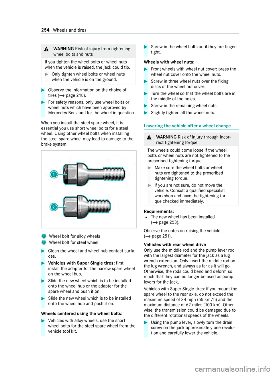
When you ins tallth esteel spare wheel, it is
essential you use short wheel bolts for a steel
wheel. Using other wheel bolts when ins talling
th esteel spare wheel may lead todamage tothe
brake sy stem. 1
Wheel bolt for alloy wheels
2 Wheel bolt forst eel wheel #
Clean the wheel and wheel hub contact sur fa‐
ces. #
Vehicles with Super Single tires: first
ins tallth e adap terfo rth e nar row spare wheel
on the wheel hub. #
Slide the new wheel which is tobe ins talled
onto the wheel hub or the adap terfo rthe
spare wheel and push it on. #
Slide the new wheel which is tobe ins talled
onto the wheel hub and push it on.
Wheels centered using the wheel bolts: #
Vehicles with alloy wheels: use the short
wheel bolts forth esteel spare wheel from the
ve hicle tool kit. #
Screw inthe wheel bolts until they are finger-
tight.
Wheels with wheel nuts: #
Front wheels with wheel nut co ver:press the
wheel nut co ver onto the wheel nuts. #
Screw inthre e wheel nuts overth efixing
discs of the wheel nut co ver. #
Turn the wheel so that the wheel bolts are in
th e middle of the holes. #
Screw inthere maining wheel nuts. #
Slightly tighten all the wheel nuts. Lo
weri ngtheve hicle af ter a wheel change &
WARNING Risk of inju rythro ugh incor‐
re ct tigh tening torque
The wheels could come loose if the wheel
bolts or wheel nuts are not tightened tothe
prescribed tightening torque. #
Makesure the wheel bolts or wheel
nuts are tightened tothe prescribed
tightening torque. #
Ifyo u are not sure, do not mo vethe
ve hicle. Consult a qualified specialist
wo rkshop and ha vethe tightening tor‐
qu ech ecked immediately. Re
quirements:
R The new wheel has been ins talled
(/ page 253).
Obser vethe no tes on raising theve hicle
(/ page 251).
Ve hicles with rear wheel drive
Only use the middle rod and the pump le verrod
with the largest diame terfo rth e jack as a lug
wrench extension. Only inse rtthe middle rod on
th e lug wrench, and alw ays as far as it will go.
Otherwise, thero ds could bend and deform so
much that they can no longer be used as pu mp
le ve rs forth e jac k.
Ve hicles with Super Single tires: if you mount the
spare wheel tothere ar axle, do not exceed the
maximum speed of 34 mph (55 km/h) and the
maximum dis tance of 62 miles (100 km). Other‐
wise, the transmission could be damaged due to
th e dif fere nt rotational speeds of the wheels. #
Using the pump le ver,slowly turn the drain
scr ew onthe jack appr oximately one revo lu‐
tion and carefully lo werth eve hicle. 254
Wheels and tires
Page 279 of 354

#
Place the jack toone side. #
Pull thero d with the smallest diame ter off the
pump le ver.
The shor tened pu mpleve r ser ves as a lug
wrench extension. #
Starting with the middle rod, slide the lug
wrench extension as far as it will go onto the
lug wrench. #
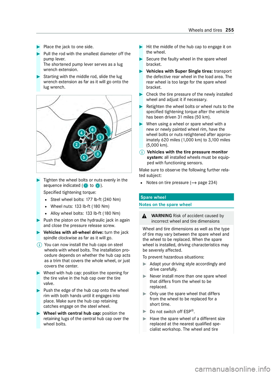
Tighten the wheel bolts or nuts evenly in the
sequence indicated (1 to6 ).
Specified tightening torque:
R Steel wheel bolts: 177 lb-ft (240 Nm)
R Wheel nuts: 133 lb-f t(180 Nm)
R Alloy wheel bolts: 133 lb-f t(180 Nm) #
Push the pis ton on thehy draulic jack in again
and close the pressure release scr ew. #
Vehicles with all-wheel drive: turnthe jack
spindle clockwise as far as it will go.
% Yo
u can now ins tallth e hub caps on steel
wheels with wheel bolts. The ins tallation pro‐
cedure depends on whe ther the hub cap acts
as a trim that co vers the whole wheel, or just
co vers the center. #
Wheel with hub cap: position the opening for
th e tire valve in the hub cap overth e tire
va lve. #
Push the edge of the hub cap onto the wheel
ri m with bo thhands until it engages into
place. Make sure the hub cap retaining
cat ches engage on thesteel wheel. #
Wheel with central hub cap: positionthe
re taining lugs of the cent ral hub cap overthe
wheel bolts. #
Hitthe middle of the hub cap toengage it on
th e wheel. #
Secure thefa ulty wheel in the spare wheel
brac ket. #
Vehicles with Super Single tires: transport
th e defective rear wheel in the load area. The
re ar wheel is too lar geforth e spare wheel
brac ket. #
Check the tire pressure of the newly ins talled
wheel and adjust it if necessar y. #
Retighten the wheel bolts or wheel nuts tothe
specified tightening torque af terth eve hicle
has been driven 31miles (50 km). #
When using a wheel or spare wheel with a
new or newly painted wheel rim, ha vethe
wheel bolts or nuts retightened af ter appro x‐
ima tely 620 miles (1,000 km) to3,10 0 miles
(5,000 km).
% Ve
hicles with the tire pressure monitor
sy stem: all ins talled wheels must be equip‐
ped with functioning sensors.
Make sure toobser vethefo llowing fur ther rela‐
te d subject:
R Notes on tire pressure (/ page 234) Spare wheel
Note
s onthe spa rewheel &
WARNING Risk of accident caused by
incor rect wheel and tire dimensions
Wheel and tire dimensions as well as the type
of tire may vary between the spare wheel and
th e wheel tobe replaced. When the spare
wheel is ins talled, driving characteristics may
be se verely af fected.
To prev ent hazardous situations: #
Adapt your driving style according lyand
drive carefull y. #
Never ins tall more than one spare wheel
th at dif fers from the wheel tobe
re placed. #
Only use the spare wheel that dif fers
from the wheel tobe replaced for a
short time. #
Do not switch off ESP ®
. #
Have the spare wheel of a dif fere nt size
re placed at the nearest qualified spe‐
cialist workshop. The wheel and tire Wheels and tires
255