wheel MERCEDES-BENZ SPRINTER 2020 MY20 Fuse Allocation Supplement
[x] Cancel search | Manufacturer: MERCEDES-BENZ, Model Year: 2020, Model line: SPRINTER, Model: MERCEDES-BENZ SPRINTER 2020Pages: 20, PDF Size: 0.98 MB
Page 6 of 20

Fu
ses/rela ysinthef ront-passenger foot we ll Fu
se assignment No
.C onsumer Fuse
ra t–
ing
MF1
15 -2 Engine control uni t5A
15 -2 Common Powe rtra in Module
(CPC) 5A
15 -2
ESP®
control unit 5A
15 -2 All-wheel driv econtrol uni t5A
15 -2 Onboard Logistic Unit con‐
trol unit 5A
15 -2 Term inal 15,special signal,
cockpit body manufacturer 5A
MF2
15 -1 Feedbac kcable, term inal 15
re lay 5A
15 -1 Headlamp rang ea djustment,
halo genh eadlamps 5A
15 -1 Tach ograph TCO5 A
15 -1 ActiveB rake Assi stradar
sensor 5A No
.C onsumer Fuse
ra t–
ing
15 -1 Deactivation of reve rse
wa rning device ,powe rtake-
off, working speed control 5A
15 -1 DIN slo tconnection 5A
MF3
30- TM ultifunction camera 7.5A
30- TU nassigned
30- TD IN slotconnection, roof 7.5A
30- TT erminal 30T ,special signal,
cockpit body manufacturer 7.
5A
30- TI nstrument clu ster 7.5A
30- TD IN slot, cockpit 7.5A
S9
1U nassigned
2C ommonPowe rtra in Module
(CPC) 10 A
3E ngine control uni tOM642/
OM651/M2 74 10 A 4
Fuse/rela yassignment diagram
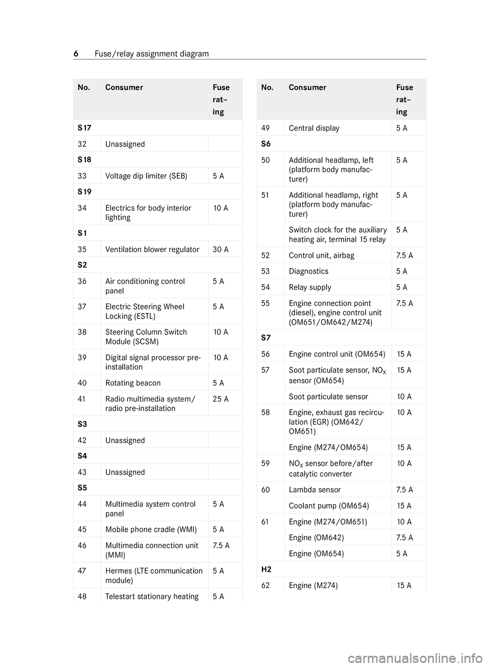
Page 8 of 20

No
.C onsumer Fuse
ra t–
ing
S17
32 Unassigned
S18
33 Voltag edip limiter (SEB) 5A
S19
34 Electrics forb ody interior
lighting 10 A
S1
35 Ventilation bl owerregulator 30 A
S2
36 Air conditioning cont rol
panel 5A
37 ElectricSteering Wheel
Locking (ESTL) 5A
38 Steering Column Switch
Module (SCSM) 10 A
39 Digital signa lprocesso rpre-
ins tallation 10 A
40 Rotating beaco n5 A
41 Radio multimedia sy stem/
ra dio pre-ins tallation 25 A
S3
42 Unassigned
S4
43 Unassigned
S5
44 Multimedia sy stem cont rol
panel 5A
45 Mobile phone cradle (WMI) 5A
46 Multimedia connection unit (MMI) 7.
5A
47 Hermes (LTE communication
module) 5A
48 Teles tart stationar yheating 5A No
.C onsumer Fuse
ra t–
ing
49 Central displ ay5A
S6
50 Additional headlamp, left
(platfor mbody manufac‐
turer) 5A
51 Additional headlamp, right
(platfor mbody manufac‐
turer) 5A
Switc hclockfor thea uxiliary
heating air ,terminal 15relay 5A
52 Cont rolu nit ,airbag 7.5A
53 Diagno stics 5A
54 Relays uppl y5 A
55 Engine connection point (diesel), engine control unit
(OM651/OM642/M2 74 )7.
5A
S7
56 Engine control unit (OM654) 15 A
57 Sootparticulat esensor ,NO
X
sensor (OM654) 15 A
Soo tparticulat esensor 10 A
58 Engine, exhaus tgas recircu‐
lation (EGR) (OM 642/
OM651) 10 A
Engine (M 274/OM654) 15 A
59 NO Xsensor before/af
ter
catalytic con verter 10 A
60 Lambda sensor 7.5A
Coolant pump (OM654) 15 A
61 Engine (M 274/OM651) 10 A
Engine (OM 642) 7.5A
Engine (OM654) 5A
H2
62 Engine (M2 74)1 5A 6
Fuse/rela yassignment diagram
Page 11 of 20

Fu
se bloc kF55/1 No
.C onsumer Fuse
ra t–
ing
1A dditional tur nsignal lam p10A
Ro ofventilator 15 A
2R ear windo wwiper,right 15 A
3A ll-wheeldrive control unit 30 A
4MATIC all-wheel driv econ‐
trol unit 30 A
4P arkingPacka ge 5A
Re ar vie wcamera
5D rive rs eat adjustment con‐
trol unit 25 A
Driver's seat heating control
unit
6D rive rlumbar suppor t10A
Co-driver lumbar support
7C o-driver seat adjustment
contro lunit 25 A
Co-driver seat heatin gcontrol
unit (double jum pseat)
8T irep ressur emonitor control
unit 5A
Motion de tector and tire
pressur emonitor control unit
9T erminal 30, term inal stripf or
body manufacturer's electri‐
cal connection 25 AFu
se bloc kF55/2 No
.C onsumer Fuse
ra t–
ing
10 Trailer coupling control unit,
ri ght 25 A
11 Trailer coupling control unit
(soc ket) 15 A
12 Trailer coupling control unit,
left 25 A No
.C onsumer Fuse
ra t–
ing
13 Trailer coupling control unit
(chargin gcable) 15 A
14 Parame terizable specia lmod‐
ul ec ontrol unit 25 A
15 Parame terizable specia lmod‐
ul ec ontrol unit 25 A
16 Rear blo wer2 5A
17 Hot-water auxiliar yheater2 0A
18 Term inal 30T fort erminal 15
re lay 5A Fu
se bloc kF55/3 No
.C onsumer Fuse
ra t–
ing
19 Rear wind owheater ,lef t1 5A
Ad ditional car avanin gunit
(PWM 1) 30 A
20 Rear wind owheater ,right 15 A
Ad ditional car avanin gunit
(PWM 2) 30 A
21 Rear wind owheater relay3 0A
Ad ditional car avanin gunit
control unit 5A
22 Trailer brak eboos ter3 0A
23 Cargo liftgate/du mpervehi‐
cle (pre-ins tallation) 7.
5A
Ro ofventilator 5A
24 Term inal stripf or elect rical
connection (bod ymanufac‐
turer) 15 A
25 Rear vie wcamer afor inside
re arvie wmirro r/rear view
camer apre-ins tallation 5A
Re ar vie wcamer adispla y,
inside rearvie wmirror
26 Auxilia rywa rm-airh eater1 5A Fu
se/rela yassignment diagram 9