lights MERCEDES-BENZ V-CLASS MPV 2021 Owners Manual
[x] Cancel search | Manufacturer: MERCEDES-BENZ, Model Year: 2021, Model line: V-CLASS MPV, Model: MERCEDES-BENZ V-CLASS MPV 2021Pages: 337, PDF Size: 9.88 MB
Page 10 of 337
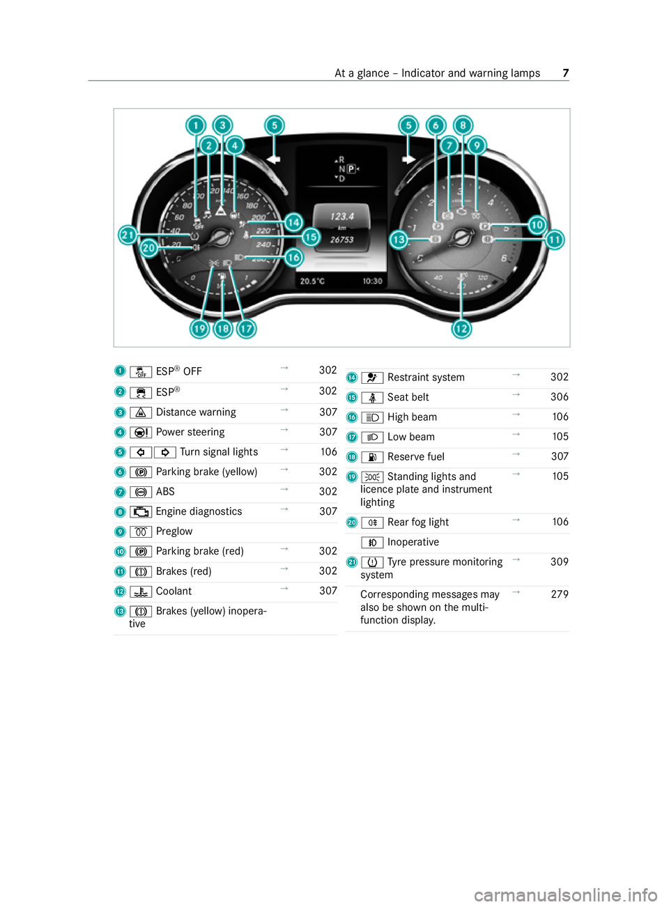
1
00BB ESP®
OFF →
302
2 00E5 ESP®
→
302
3 00BA Distance warning →
307
4 00CC Powe rst eering →
307
5 003E003D Turn signal lights →
106
6 0024 Parking brake (yellow) →
302
7 0025 ABS →
302
8 00B9 Engine diagnostics →
307
9 0028 Preglow
A 0024 Parking brake (red) →
302
B 004D Brakes (red) →
302
C 00AC Coolant →
307
D 004D Brakes (yellow) inopera‐
tive E
0075 Restra int sy stem →
302
F 00E9 Seat belt →
306
G 0057 High beam →
106
H 0058 Low beam →
105
I 00B4 Reser vefuel →
307
J 0060 Standing lights and
licence plate and instrument
lighting →
105
K 005E Rear fog light →
106
005A Inoperative
L 0077 Tyre pressure monitoring
sy stem →
309
Cor responding messages may
also be shown on the multi‐
function displa y. →
279 At
aglance – Indicator and warning lamps 7
Page 28 of 337
Gene
rally, these are volatile data and will not be
st ored be yond the period of operation but will
only be processed within theve hicle itself. Con‐
trol units, vehicle keys forex ample, of ten contain
da ta memories. Their use permits thete mp orary
or permanent documentation of tech nical infor‐
mation about theve hicle's operating state, com‐
ponent loads, main tenance requirements and
te ch nical events or faults.
Depending on thete ch nical equipment, thefo l‐
lowing data are stored:
R operating status of sy stem components, such
as fill le vels, tyre pressure or battery status
R malfunctions or faults in impor tant sy stem
components, such as lights or brakes
R system reactions in special driving situations,
such as airbag deployment or the inter vention
of stability control sy stems
R information on events in which theve hicle is
damaged
In cer tain cases, it may be requ ired tostore data
th at wo uld ha veotherwise been temp orar y.This
may be the case if theve hicle has de tected a
malfunction, forex ample.
If yo u use services, such as repair services and
maintenance work,st ored operational data as
we ll as theve hicle identification number can be
re ad out and used. They can be read out by
service network emplo yees, such as workshops
and manufacturers or third parties, such as
breakdown services. The same is true in the case
of wa rranty claims and quality assurance meas‐
ures.
In general, there adout is per form ed via the
legally prescribed port forth e diagnostics con‐
nection in theve hicle. The operational data that
are read out document tech nical states of the
ve hicle or of individual components and assist in
th e diagnosis of malfunctions, compliance with
wa rranty obligations and quality impr ovement. To
th at end, these data, in particular information
about component loads, tech nical events, mal‐
functions and other faults may be transmitted
along with theve hicle identification number to
th e manufacturer. In addition, the manufacturer is
subject toproduct liability. Forth is reason, the
manufacturer also uses operational data from the
ve hicle, forex ample, forre calls. These data can
also be used toexamine the cus tomer's warranty
and guarantee claims. Fa
ult memories in theve hicle can be reset by a
service outlet or at your requ est as part of repair
or maintenance work.
Con venience and inf otainment functions
Yo u can store con venience settings and individual
settings in theve hicle and change or reset them
at any time.
Depending on theve hicle equipment, this
includes thefo llowing settings, forex ample:
R seat and steering wheel positions
R suspension and climate cont rol settings
R individual settings, such as interior lighting
Depending on the selected equipment, you can
import data into vehicle inf otainment functions
yo urself.
Depending on theve hicle equipment, this
includes thefo llowing data, forex ample:
R multimedia data, such as music, films or pho‐
to sfo r playback in an integrated multimedia
sy stem
R address book data for use in an integrated
hands-free sy stem or an integrated navigation
sy stem
R entered navigation destinations
R data on the use of Internet services
These data for con venience and inf otainment
functions may be sa ved locally in theve hicle or
th ey may be located on a device which you ha ve
connected totheve hicle, such as a smartphone,
USB flash drive or MP3 pla yer.If yo u ha ve
entered these data yourself, you can dele tethem
at any time.
This data is transmit ted from theve hicle tothird
parties only at your requ est. This applies, in par‐
ticular, when you use online services in accord‐
ance with the settings that you ha veselected.
Smartphone integ ration (e.g. Android Autoor
Apple CarPlay ®
)
If yo ur vehicle is equipped appropriatel y,yo u can
connect your smartphone or ano ther mobile end
device totheve hicle. You can then cont rolth em
by means of the cont rol elements integrated in
th eve hicle. The smartphone's picture and sound
can be output via the multimedia sy stem. Simul‐
ta neously, specific items of information are trans‐
fe rred to yo ur smartphone. Depending on the
type of integration, this includes position data,
day/night mode and other general vehicle sta‐
tuses. For more information, please consult the Gene
ral no tes 25
Page 30 of 337

Re
stra int sy stem Pr
otection pr ovided bythere stra int sy stem The
restra int sy stem includes thefo llowing com‐
ponents:
R Seat belt sy stem
R Airbags
R Child restra int sy stem
R Child seat securing sy stems
The restra int sy stem can help pr eventtheve hicle
occupants from coming into contact with parts of
th eve hicle interior in theeve nt of an accident. In
th eeve nt of an accident, there stra int sy stem can
also reduce thefo rc es towhich theve hicle occu‐
pants are subjected.
Only a seat belt which is worncor rectly can pro‐
vide the intended le vel of pr otection. Depending
on the de tected accident situation, seat belt ten‐
sioners and/or airbags supplement the pr otec‐
tion of fere dby a cor rectly wornseat belt. Seat
belt tensioners and/or airbags are not depl oyed
in eve ryaccident.
In order forth ere stra int sy stem toprov ide the
intended le vel of pr otection, each vehicle occu‐
pant must obser vethefo llowing information:
R Fasten seat belts cor rectl y.
R Sit in an almost up right seat position with
th eir back against the seat backrest.
R Sit with their feet resting on thefloor, if possi‐
ble.
R Always secure persons under 1.50 m ta ll in
an additional restra int sy stem suitable for
Mercedes-Benz vehicles.
Ho wever,no sy stem available today can com‐
ple tely eliminate injuries and fata lities in every
accident situation. In particular, the seat belt and
airbag general lydo not pr otect against objects
penetrating theve hicle from the outside. It is also
not possible tocomple tely rule out therisk of
injury caused bythe airbag deploying. Limited pr
otection pr ovided bythere stra int
sy stem &
WARNING Risk of injury or death dueto
modifications tothere stra int sy stem
Ve hicle occupants may no longer be pr otec‐
te d as intended if alterations are made tothe
re stra int sy stem. #
Never alter the parts of there stra int
sy stem. #
Neverta mp er with the wiring or any
electronic component parts or their
software. If it is necessary
toadjust theve hicle toaccom‐
modate a person with disabilities, con tact a quali‐
fi ed specialist workshop.
Mercedes-Benz recommends that you on lyuse
driving aids which ha vebeen appr oved specifi‐
cally foryo ur vehicle byMercedes-Benz. Re
stra int sy stem functionality When
the ignition is switched on, a self-test is
per form ed, during which the0075 restra int sys‐
te m wa rning lamp lights up. It goes out no later
th an a few seconds af terth eve hicle is star ted.
The components of there stra int sy stem are then
functional. Re
stra int sy stem malfunction A malfunction has occur
red in there stra int sys‐
te m in thefo llowing cases:
R The 0075 restra int sy stem warning lamp does
not light up when the ignition is switched on.
R The 0075 restra int sy stem warning lamp
lights up continuously or repeatedly during a
journe y. &
WARNING Risk of injury duetomalfunc‐
tions in there stra int sy stem
Components in there stra int sy stem may be
activated unintentionally or not deploy as
intended in an accident. #
Have there stra int sy stem checked and
re paired immediately at a qualified spe‐
cialist workshop. Fu
nction of there stra int sy stem in an acci‐
dent How
there stra int sy stem works is de term ined by
th e se verity of the impact de tected and the type
of accident anticipated:
R frontal impact
R rear impact
R side impact Occupant saf
ety27
Page 37 of 337

The co-driver airbag may
otherwise be disabled
by mis take ,fo rex ample, in thefo llowing situa‐
tions:
R The co-driver transfers their weight bysup‐
porting themselves on a vehicle armrest.
R The co-driver sits in such a wayth at their
we ight is raised from the sitting sur face. &
WARNING Risk of injury or death dueto
a disabled front passenger airbag
The front passenger airbag is disabled when
th ePA SSENGER AIR BAG OFF indicator lamp
is lit.
A person in the front passenger seat could
th en, forex ample, come into con tact with the
ve hicle interior, especially if the person is sit‐
ting too close tothe cockpit.
If th e front passenger seat is occupied,
alw ays ensure that:
R the classification of the person in the
front passenger seat is cor rect and the
front passenger airbag is enabled or disa‐
bled in accordance with the person in the
front passenger seat.
R the front passenger seat has been mo ved
as far back as possible.
R the person is seated cor rectly. #
Both before and during the journe y,
ensure that thest atus of the front
passenger airbag is cor rect. If
th e co-driver seat is occupied, the classification
of the person or child restra int sy stem on the co-
driver seat take s place af terth e co-driver airbag
shutoff self-test. The PASSENGER AIR BAG OFF
indicator lamp displa ys thest atus of the co-driver
airbag.
Alw ays obser vethe no tes on the function of the
PA SSENGER AIR BAG OFF indicator lamp
(/ page 34). Fu
nction of thePA SSENGER AIR BAG indicator
lamps The
PASSENGER AIR BAG ON indicator lamp is
inoperative. When the ignition is switched on, it
lights up brief lyand then goes out again. Only the
PA SSENGER AIR BAG OFF indicator lamp displa ys
th est atus of the co-driver airbag. The
PA SSENGER AIR BAG OFF indicator lamp may be
lit continuously or be off.
Ve hicles without an automatic co-driver airbag
shutoff ha vea special sticke r af fixe dto the side
of the cockpit on the co-driver side
(/ page 45).
Self-test of automatic co-driver airbag shutoff
The PASSENGER AIR BAG OFF indicator lamp
lights up for appro ximately six seconds du ring the
self-test when the ignition is switched on.
The status of the co-driver airbag is displa yed
af te rth e self-tes t:
R PASSENGER AIR BAG OFF is not lit: the co-
driver airbag may deploy during an accident.
R PASSENGER AIR BAG OFF lights up continu‐
ously: the co-driver airbag is disabled. It will
not be deplo yed in theeve nt of an accident.
If th ePA SSENGER AIR BAG OFF indicator lamp
and the0075 restra int sy stem warning lamp light
up simultaneousl y,the co-driver seat may not be
used. Also in this case, do not fit a child restra int
sy stem tothe co-driver seat. Ha vethe automatic
co-driver airbag shutoff checked and repaired
immediately at a qualified specialist workshop.
St atus indicator
If th e co-driver seat is occupied, ensure, bo th
before and during the journe y,that thest atus of 34
Occupant saf ety
Page 38 of 337

th
e co-driver airbag is cor rect forth e cur rent sit‐
uation.
Af terfitting a rear wa rd-facing child restra int
sy stem tothe co-d rive r seat: PASSENGER AIR
BA G OFF must be lit continuousl y.&
WARNING Risk of injury or death when
using a rear wa rd-facing child restra int
sy stem while the front passenger airbag
is enabled
If yo u secure a child in a rear wa rd-facing child
re stra int sy stem on the front passenger seat
and thePA SSENGER AIR BAG OFF indicator
lamp is off, the front passenger airbag can
deploy in theeve nt of an accident.
The child could be stru ck bythe airbag. #
Always ensure that the front passenger
airbag is disabled. The PASSENGER AIR
BA G OFF indicator lamp must be lit. #
NEVER use a rear wa rd-facing child
re stra int sy stem on a seat with an ENA‐
BLED FRONT AIRB AG. This can result in
th e DEAT H of or SERIOUS INJURY tothe
CH ILD. When
fitting a child restra int sy stem tothe co-
driver seat, obser vetheve hicle-specific informa‐
tion (/ page 46).
Depending on thech ild restra int sy stem and the
st ature of thech ild, thePA SSENGER AIR BAG
OFF indicator lamp may be off. In this case, do
not fit th ere ar wa rd-facing child restra int sy stem
to the co-driver seat.
Ins tead, fit th ere ar wa rd-facing child restra int
sy stem toa suitable rear seat.
Af terfitting a forw ard-facing child restra int
sy stem tothe co-d rive r seat: depending on the
ch ild restra int sy stem and thest ature of the
ch ild, PASSENGER AIR BAG OFF may be lit con‐
tinuously or be off. Alw ays obser vethefo llowing
information. &
WARNING Risk of injury or death dueto
incor rect positioning of thefo rw ard-
fa cing child restra int sy stem
If yo u secure a child in a forw ard-facing child
re stra int sy stem on the front passenger seat
th at is positioned too close tothe cockpit, in
th eev ent of an accident, thech ild could:
R come into con tact with th eve hicle interior
if th ePA SSENGER AIR BAG OFF indicator
lamp is lit, forex ample
R bestru ck bythe airbag if thePA SSENGER
AIR BAG OFF indicator lamp is off. #
Always mo vethe front passenger seat
as far back as possible and fully retract
th e seat cushion length adjustment.
While doing so, alw ays make sure that
th e shoulder belt stra p is cor rectly
ro uted from the seat belt outlet of the
ve hicle tothe shoulder belt guide on the
ch ild restra int sy stem. The shoulder belt
st ra p must be routed forw ards and
down wards fr omthe seat belt outlet. If
necessar y,adjust the seat belt outlet
and the front passenger seat accord‐
ingly. #
Always comply with thech ild restra int
sy stem manufacturer's ins tallation
instructions. When
fitting a child restra int sy stem tothe co-
driver seat, obser vetheve hicle-specific informa‐
tion (/ page 46).
If a person is sitting on the co-d rive r seat:
PA SSENGER AIR BAG OFF may be lit continuously
or be off, depending on the person's stature.
A person on the co-driver seat must alw ays
obser vethefo llowing information:
R Ifth e co-driver seat is occupied byan adult or
a person with a stature cor responding tothat
of an adult, thePA SSENGER AIR BAG OFF
indicator lamp must be off. This indicates that
th e co-driver airbag is enabled.
If th ePA SSENGER AIR BAG OFF indicator
lamp is lit continuousl y,an adult or person
with a build cor responding tothat of an adult
should not use the co-driver seat.
Ins tead, they should use a rear seat.
R Ifth e co-driver seat is occupied bya person
of smaller stature (e.g. a teenager or small
adult), thePA SSENGER AIR BAG OFF indica‐
to r lamp either lights up continuously or Occupant saf
ety35
Page 39 of 337
re
mains off, depending on there sult of the
classi fication.
- Ifth ePA SSENGER AIR BAG OFF indicator
lamp is off: mo vethe co-driver seat as far
back as possible, or the person of smaller
st ature should use a rear seat.
- Ifth ePA SSENGER AIR BAG OFF indicator
lamp is lit continuously: the person of
smaller stature should not use the co-
driver seat. &
WARNING Risk of injury or death when
th ePA SSENGER AIR BAG OFF indicator
lamp is lit
If th ePA SSENGER AIR BAG OFF indicator
lamp remains lit af terth e self-test, the front
passenger airbag is disabled.
If th e front passenger seat is occupied,
alw ays ensure that:
R The classification of the person in the
front passenger seat is cor rect and the
front passenger airbag is enabled or disa‐
bled in accordance with the person in the
front passenger seat.
R The person is seated properly with a cor‐
rectly fastened seat belt.
R The front passenger seat has been mo ved
as far back as possible. Be sure
toalso obse rveth efo llowing fur ther rela‐
te d subjects:
R Child restra int sy stem on the co-driver seat
(/ page 46).
R Suitable positioning of thech ild restra int sys‐
te m (/ page 40). PRE-SAFE
®
Sy stem Fu
nction of PRE-SAFE ®
(anticipatory occupant
pr otection) PRE-
SAFE®
can de tect cer tain hazardous situa‐
tions and take pre-em ptive measures toprotect
th eve hicle occupants.
PRE-SAFE ®
can implement thefo llowing meas‐
ures independently of each other:
R Tightening the seat belts on the driver's seat
and co-driver seat.
R Closing the side windo ws. R
Vehicles with a sliding sunroof: closingthe
sliding sunroof.
R Vehicles with memory function: adjusting
th e co-driver seat toa more favo urable seat
position.
* NO
TEDama gecaused byobjects in the
fo ot we ll or behind the seat The automatic adjustment of
the seat posi‐
tion may result in damage tothe seat and/or
th e object. #
Stow objects in a suitable place. Re
versing the PRE- SAFE®
sy stem measures If an accident did not occur,
the pre-em ptive
measures that we retak en are reve rsed.
Yo u will need tomake cer tain adjustments your‐
self. #
Ifth e seat belt pre-tensioning is not reduced,
mo vethe seat backrest back slightl y.
The locking mechanism releases. Au
tomatic measures af ter an accident
Depending on the type and se verity of the acci‐
dent, and depending on theve hicle's equipment,
th efo llowing measures can be implemente d,for
ex ample:
R activating the hazard warning lights
R triggering an automatic emer gency call
(/ page 233)
R switching off the engine
To restart theve hicle, switch the ignition off
and switch it back on (/ page136). Depend‐
ing on the type and se verity of the accident, it
may possible that theve hicle can no longer
be star ted.
R switching off the fuel supply
R unlocking theve hicle doors
R lowe ring the front side windo ws
R switching on the interior lighting 36
Occupant saf ety
Page 71 of 337
Deactivating
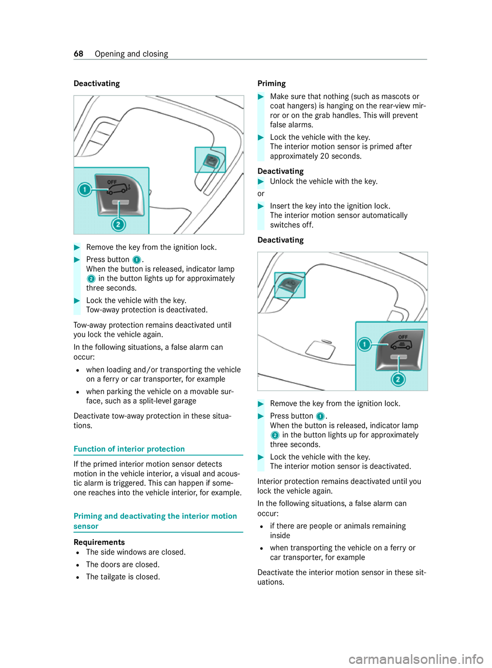
#
Remo vetheke y from the ignition loc k. #
Press button 1.
When the button is released, indicator lamp
2 inthe button lights up for appro ximately
th re e seconds. #
Lock theve hicle with thekey.
To w- aw ay protection is deactivated.
To w- aw ay protection remains deactivated until
yo u lock theve hicle again.
In thefo llowing situations, a false alarm can
occur:
R when loading and/or transporting theve hicle
on a ferry or car transpor ter,fo rex ample
R when parking theve hicle on a mo vable sur‐
fa ce, such as a split-le velga rage
Deactivate tow- aw ay protection in these situa‐
tions. Fu
nction of interior pr otection If
th e primed interior motion sensor de tects
motion in theve hicle interior, a visual and acous‐
tic alarm is triggered. This can happen if some‐
one reaches into theve hicle interior, forex ample. Priming and deactivating
the interior motion
sensor Requ
irements
R The side windo wsare closed.
R The doors are closed.
R The tailgate is closed. Priming #
Make sure that no thing (such as masc ots or
coat hangers) is hanging on there ar-view mir‐
ro r or on the grab handles. This will pr event
fa lse alarms. #
Lock theve hicle with thekey.
The interior motion sensor is primed af ter
appr oximately 20 seconds.
Deactivating #
Unlock theve hicle with thekey.
or #
Insert theke y into the ignition loc k.
The interior motion sensor automatically
switches off.
Deactivating #
Remo vetheke y from the ignition loc k. #
Press button 1.
When the button is released, indicator lamp
2 inthe button lights up for appro ximately
th re e seconds. #
Lock theve hicle with thekey.
The interior motion sensor is deactivated.
Interior pr otection remains deactivated until you
lock theve hicle again.
In thefo llowing situations, a false alarm can
occur:
R ifth ere are people or animals remaining
inside
R when transporting theve hicle on a ferry or
car transpor ter,fo rex ample
Deactivate the interior motion sensor in these sit‐
uations. 68
Opening and closing
Page 104 of 337
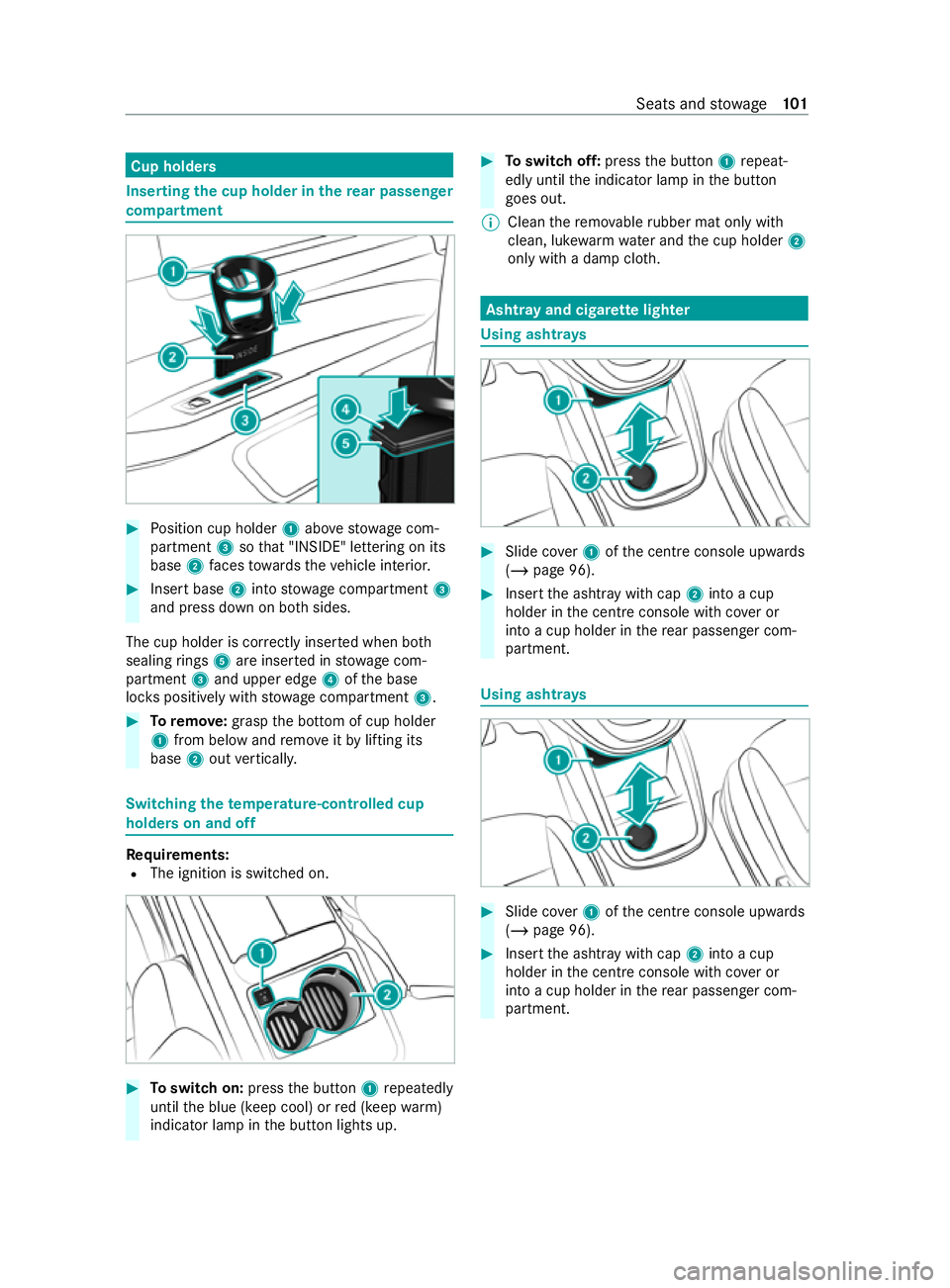
Cup holders
Inserting
the cup holder in there ar passen ger
compa rtment #
Position cup holder 1abo vestow age com‐
partment 3sothat "INSIDE" lettering on its
base 2faces towa rdsth eve hicle interior. #
Insert base 2into stow age compartment 3
and press down on bo thsides.
The cup holder is cor rectly inse rted when bo th
sealing rings 5are inse rted in stowage com‐
partment 3and upper edge 4ofthe base
loc kspositively with stowage compartment 3. #
Toremo ve: grasp the bottom of cup holder
1 from below and remo veitby lifting its
base 2out verticall y. Switching
thetemp erature-cont rolled cup
holders on and off Re
quirements:
R The ignition is switched on. #
Toswitch on: pressthe button 1repeatedly
until the blue (keep cool) or red (keep warm)
indicator lamp in the button lights up. #
Toswitch off: pressthe button 1repeat‐
edly until the indicator lamp in the button
goes out.
% Clean
there mo vable rubber mat only with
clean, luk ewarmwate r and the cup holder 2
only with a damp clo th. Asht
ray and cigar ette lighter Using asht
rays #
Slide co ver1 ofthe cent reconsole up wards
( / page 96). #
Insert the ashtr aywith cap 2into a cup
holder in the cent reconsole wi thcover or
into a cup holder in there ar passenger com‐
partment. Using ashtr
ays #
Slide co ver1 ofthe cent reconsole up wards
( / page 96). #
Insert the ashtr aywith cap 2into a cup
holder in the cent reconsole wi thcover or
into a cup holder in there ar passenger com‐
partment. Seats and
stowage 101
Page 107 of 337

#
Insert the plug of the device into 230 V
soc ket3.
When the on-board electrical sy stem voltage
is suf ficient, indicator la mp1lights up.
When you are not using the 230 V po wer soc ket,
ke ep theflap closed. Swit
ching there frigerator box in the centre
console on and off &
WARNING Risk offire due toa co vered
ve ntilation grille on the coolbox
If yo u co verth eve ntilation grille forth e cool‐
box, it may overheat. #
Always make sure that theve ntilation
grille is not co vered. The coolbox
ventilation grille is between the front
seat base and the cent reconsole sid ewall.
Re quirements
R The ignition is switched on.
R The stow age compartment under the armrest
is open (/ page 96). The
refrigerator box can bear a maximum load of
3.5 kg. #
Toopen: fold co ver1 upwards. #
Toswitch the cooling le velto low: press
button 2for appro ximately two seconds. #
Toswitch the cooling le velto high: press
button 2again. #
Toswitch off: press button 2for appro x‐
ima tely two seconds until all indica tor lamps
go out. %
If
yo u do not need touse there frigerator box
fo r an extended pe riod, you should swit chit
off, defrost it and clean it. Af ter doing so,
lea vethe cap open for a time. Note
s on attaching the iPad ® Yo
ur vehicle is equipped with iPad ®
attachment
1 onthe driver's and co-driver's seat backrests.
A mount, which has been tested and appr oved
especially for Mercedes-Benz vehicles, is availa‐
ble as an accesso ry. Only this mount can unlock
th e attachment opening and allow the iPad ®
to
be charge d whilst it is ins talled.
iPad ®
attachment 1may only be used for
accesso ries up to42 W (3.5 A).
Contact a Mercedes-Benz Service Centre for
information and availabilit y.Before using the
mount, please read the operating instructions for
th e mount.
% Only use accessories which ha
vebeen tested
and recommended byMercedes-Benz. 104
Seats and stowage
Page 108 of 337

Exterior lighting
Note
s onchanging the lights when driving
abroad Low beam
In countries in which traf
fic drives on the oppo‐
site side of thero ad from the count ryin which
th eve hicle is regis tere d, you will ha vetoswitch
th e headlamps tosymmetrical dipped beam. This
will pr event oncoming traf fic from being dazzled.
Symm etrical dipped beam will no longer illumi‐
nate the edge of the car riag ew ay as far or as
high.
Ve hicles with halogen headlamps:
It is not necessa ryto change the headlamps over
to symmetrical dipped beam. The statutory
re qu irements of the count ries in which traf fic
drives on the opposite side of thero ad from the
country in whi chtheve hicle is regis tere d will also
be met without changing over.
Ve hicles with LED headlamps:
Yo u can set the low beam for driving on theright
or left via the on-board computer (/ page189). Infor
mation about lighting sy stems and your
re sponsibility The
vehicle's various lighting sy stems are only
aids. The vehicle driver is responsible for adjust‐
ing theve hicle's lighting tothe pr evailing light,
visibilit y,statutory conditions and traf fic condi‐
tions. Light switch
Operating the light switch
0047
0063 Left pa rking lights
0048 0064 Right parking lights
0049 0060 Standing lights and licence plate and
instrument lighting
004A 0058 Automatic driving lights (prefer red light
switch position)
004B 0058 Low beam or high beam
6 005E Rear fog light
7 005A Front fog lamp
If yo u hear a warning tone when exiting theve hi‐
cle, the lights may still be on. #
Turn the light switch to0058 .
The exterior lighting (e xcept standing and parking
lights) will automatically swit choff in thefo llow‐
ing cases:
R ifyo ure mo vetheke y from the ignition loc k.
R ifyo u open the driver's door while theke y is
in position 005Ainthe ignition loc k.
Switching on the daytime running lights #
Turn the light switch to0058 .
Au tomatic driving lights function
The standing lights, low beam and daytime run‐
ning lights will be switched on auto matically
depending on the ignition status and the light
conditions. Light and vision
105