warning Mercury Marauder 2003 s Owner's Guide
[x] Cancel search | Manufacturer: MERCURY, Model Year: 2003, Model line: Marauder, Model: Mercury Marauder 2003Pages: 232, PDF Size: 2.29 MB
Page 122 of 232
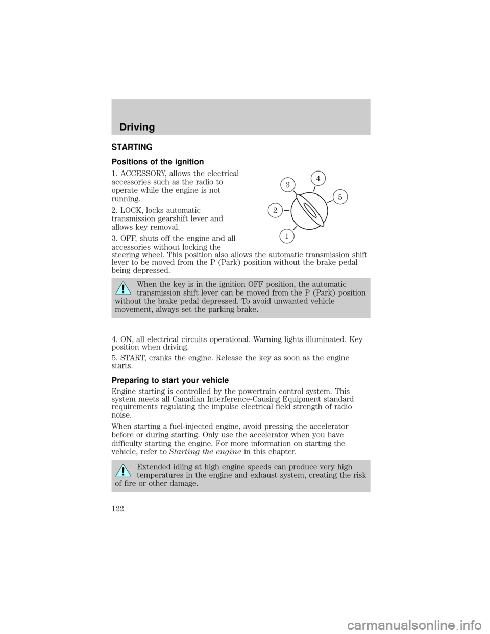
STARTING
Positions of the ignition
1. ACCESSORY, allows the electrical
accessories such as the radio to
operate while the engine is not
running.
2. LOCK, locks automatic
transmission gearshift lever and
allows key removal.
3. OFF, shuts off the engine and all
accessories without locking the
steering wheel. This position also allows the automatic transmission shift
lever to be moved from the P (Park) position without the brake pedal
being depressed.
When the key is in the ignition OFF position, the automatic
transmission shift lever can be moved from the P (Park) position
without the brake pedal depressed. To avoid unwanted vehicle
movement, always set the parking brake.
4. ON, all electrical circuits operational. Warning lights illuminated. Key
position when driving.
5. START, cranks the engine. Release the key as soon as the engine
starts.
Preparing to start your vehicle
Engine starting is controlled by the powertrain control system. This
system meets all Canadian Interference-Causing Equipment standard
requirements regulating the impulse electrical field strength of radio
noise.
When starting a fuel-injected engine, avoid pressing the accelerator
before or during starting. Only use the accelerator when you have
difficulty starting the engine. For more information on starting the
vehicle, refer toStarting the enginein this chapter.
Extended idling at high engine speeds can produce very high
temperatures in the engine and exhaust system, creating the risk
of fire or other damage.
3
1
2
5
4
Driving
122
Page 127 of 232
Using ABS
²In an emergency or when maximum efficiency from the four-wheel
ABS is required, apply continuous force on the brake. The four wheel
ABS will be activated immediately, thus allowing you to retain full
steering control of your vehicle and, providing there is sufficient
space, will enable you to avoid obstacles and bring the vehicle to a
controlled stop.
²The anti-lock system does not reduce stopping distance. Always leave
enough room between your vehicle and the vehicle in front of you to
stop.
²We recommend that you familiarize yourself with this braking
technique. However, avoid taking any unnecessary risks.
ABS warning lampABS
TheABSwarning lamp in the instrument cluster momentarily illuminates
when the ignition is turned to the ON position. If the light does not
illuminate momentarily at start up, remains on or continues to flash, the
ABS needs to be serviced.
With the ABS light on, the anti-lock
brake system is disabled and normal
braking is still effective unless the
brake warning light also remains
illuminated with parking brake
released. (If your brake warning lamp illuminates, have your vehicle
serviced immediately.)
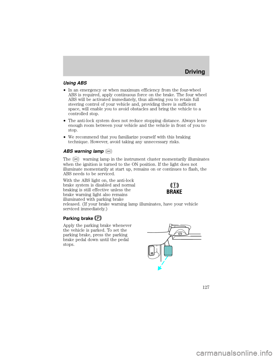
Parking brake
Apply the parking brake whenever
the vehicle is parked. To set the
parking brake, press the parking
brake pedal down until the pedal
stops.
!
BRAKE
HOOD
Driving
127
Page 128 of 232
The BRAKE warning lamp in the
instrument cluster illuminates and
remains illuminated (when the
ignition is turned ON) until the
parking brake is released.
Always set the parking brake fully and make sure that the
gearshift is securely latched in P (Park).
The parking brake is not recommended to stop a moving vehicle.
However, if the normal brakes fail, the parking brake can be used to stop
your vehicle in an emergency. Since the parking brake applies only the
rear brakes, the vehicle's stopping distance will increase greatly and the
handling of your vehicle will be adversely affected.
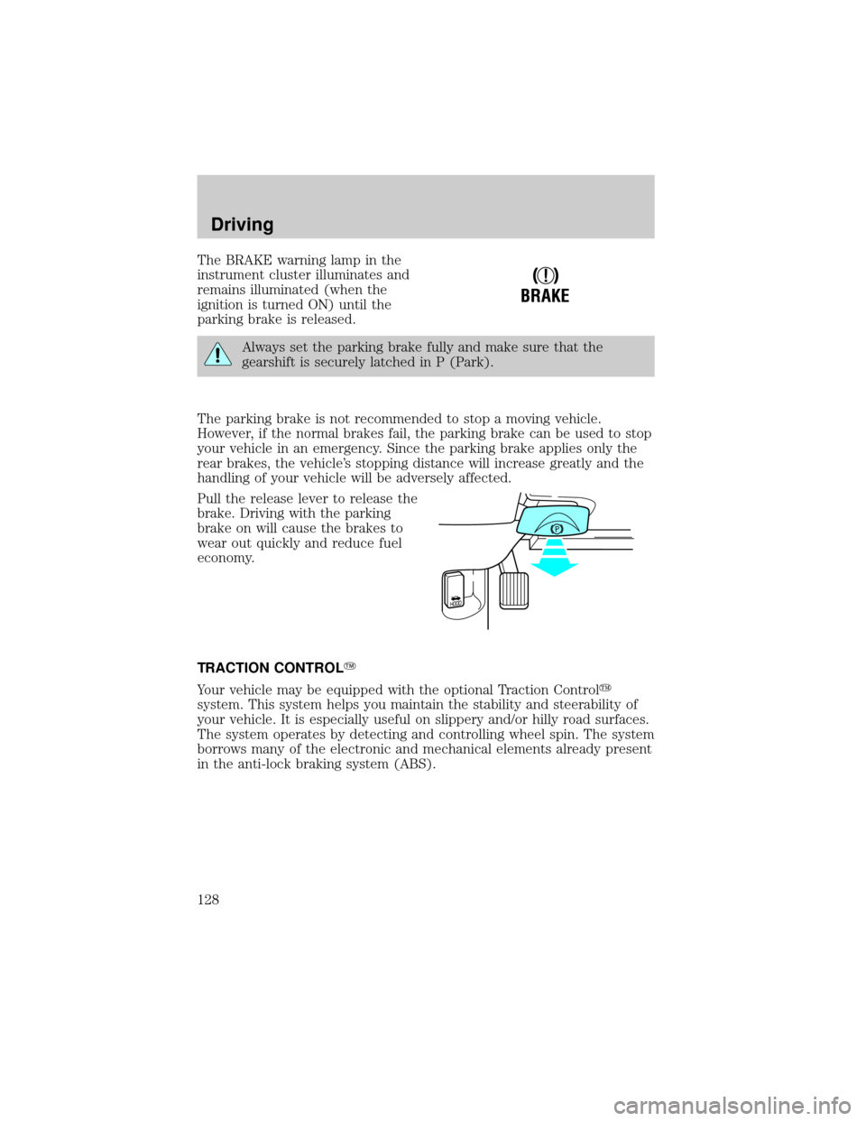
Pull the release lever to release the
brake. Driving with the parking
brake on will cause the brakes to
wear out quickly and reduce fuel
economy.
TRACTION CONTROLY
Your vehicle may be equipped with the optional Traction Controly
system. This system helps you maintain the stability and steerability of
your vehicle. It is especially useful on slippery and/or hilly road surfaces.
The system operates by detecting and controlling wheel spin. The system
borrows many of the electronic and mechanical elements already present
in the anti-lock braking system (ABS).
!
BRAKE
Driving
128
Page 131 of 232
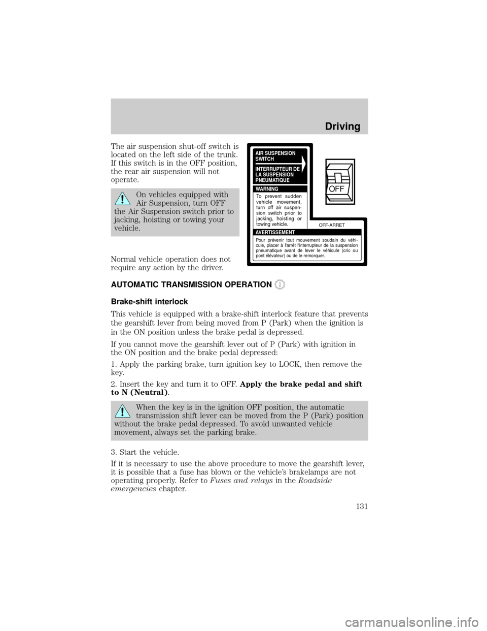
The air suspension shut-off switch is
located on the left side of the trunk.
If this switch is in the OFF position,
the rear air suspension will not
operate.
On vehicles equipped with
Air Suspension, turn OFF
the Air Suspension switch prior to
jacking, hoisting or towing your
vehicle.
Normal vehicle operation does not
require any action by the driver.
AUTOMATIC TRANSMISSION OPERATION
Brake-shift interlock
This vehicle is equipped with a brake-shift interlock feature that prevents
the gearshift lever from being moved from P (Park) when the ignition is
in the ON position unless the brake pedal is depressed.
If you cannot move the gearshift lever out of P (Park) with ignition in
the ON position and the brake pedal depressed:
1. Apply the parking brake, turn ignition key to LOCK, then remove the
key.
2. Insert the key and turn it to OFF.Apply the brake pedal and shift
to N (Neutral).
When the key is in the ignition OFF position, the automatic
transmission shift lever can be moved from the P (Park) position
without the brake pedal depressed. To avoid unwanted vehicle
movement, always set the parking brake.
3. Start the vehicle.
If it is necessary to use the above procedure to move the gearshift lever,
it is possible that a fuse has blown or the vehicle's brakelamps are not
operating properly. Refer toFuses and relaysin theRoadside
emergencieschapter.
AIR SUSPENSION
SWITCH
INTERRUPTEUR DE
LA SUSPENSION
PNEUMATIQUE
WARNING
AVERTISSEMENTOFF-ARRET
To prevent sudden
vehicle movement,
turn off air suspen-
sion switch prior to
jacking, hoisting or
towing vehicle.
Pour prévenir tout mouvement soudain du véhi-
cule, placer à l'arrêt l'interrupteur de la suspension
pneumatique avant de lever le véhicule (cric ou
pont élévateur) ou de le remorquer.
OFF
Driving
131
Page 132 of 232
Do not drive your vehicle until you verify that the brakelamps
are working.
Always set the parking brake fully and make sure the gearshift is
latched in P (Park). Turn the ignition to the LOCK position and
remove the key whenever you leave your vehicle.
If the parking brake is fully released, but the brake warning lamp
remains illuminated, the brakes may not be working properly.
See your dealer or a qualified service technician.
Driving with a 4±speed automatic transmission
Understanding gearshift positions
To put your vehicle in gear, start the engine, depress the brake pedal,
then move gearshift lever out of P (Park).
Hold the brake pedal down while you move the gearshift lever
from P (Park) to another position. If you do not hold the brake
pedal down, your vehicle may move unexpectedly and injure someone.
P (Park)
Always come to a complete stop
before shifting into P (Park). Make
sure the gearshift lever is securely
latched in P (Park). This position
locks the transmission and prevents
the rear wheels from turning.
Always set the parking
brake fully and make sure
the gearshift is latched in P
(Park). Turn the ignition to the
LOCK position and remove the
key whenever you leave your
vehicle.
P
R
N
D
2
1
Driving
132
Page 146 of 232
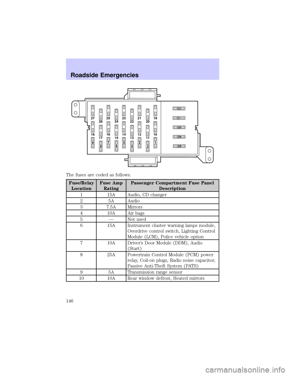
The fuses are coded as follows.
Fuse/Relay
LocationFuse Amp
RatingPassenger Compartment Fuse Panel
Description
1 15A Audio, CD changer
2 5A Audio
3 7.5A Mirrors
4 10A Air bags
5 Ð Not used
6 15A Instrument cluster warning lamps module,
Overdrive control switch, Lighting Control
Module (LCM), Police vehicle option
7 10A Driver's Door Module (DDM), Audio
(Start)
8 25A Powertrain Control Module (PCM) power
relay, Coil-on plugs, Radio noise capacitor,
Passive Anti-Theft System (PATS)
9 5A Transmission range sensor
10 10A Rear window defrost, Heated mirrors
27 25
26 2423 21
2219
20
18 16
17 1514 12
131030
32
31
28
29
11
97
8653
41
2
Roadside Emergencies
146
Page 196 of 232
Fuel Filler Cap
Your fuel tank filler cap has an indexed design with a 1/8 turn on/off
feature.
When fueling your vehicle:
1. Turn the engine off.
2. Carefully turn the filler cap counterclockwise 1/8 of a turn until it
stops.
3. Pull to remove the cap from the fuel filler pipe.
4. To install the cap, align the tabs on the cap with the notches on the
filler pipe.
5. Turn the filler cap clockwise 1/8 of a turn until it stops.
ªCheck Fuel Capº illuminates when the ignition is turned to the ON
position to ensure your bulb is working. When this light turns on, check
the fuel filler cap. Continuing to operate the vehicle with the Check Fuel
Cap light on, can activate the Service Engine Soon warning. When the
fuel filler cap is properly re-installed, the light(s) will turn off after a
period of normal driving.It may take a long period of time for the
system to detect an improperly installed fuel filler cap.
If you must replace the fuel filler cap, replace it with a fuel filler
cap that is designed for your vehicle. The customer warranty may
be void for any damage to the fuel tank or fuel system if the
correct genuine Ford or Motorcraft fuel filler cap is not used.
The fuel system may be under pressure. If the fuel filler cap is
venting vapor or if you hear a hissing sound, wait until it stops
before completely removing the fuel filler cap. Otherwise, fuel may
spray out and injure you or others.
If you do not use the proper fuel filler cap, excessive pressure or
vacuum in the fuel tank may damage the fuel system or cause
the fuel cap to disengage in a collision, which may result in possible
personal injury.
Choosing the right fuel
Use only UNLEADED FUEL. The use of leaded fuel is prohibited by law
and could damage your vehicle.
Do not use fuel containing methanol. It can damage critical fuel system
components.
Maintenance and Specifications
196
Page 202 of 232
²Do not turn off the ignition while your vehicle is moving, especially at
high speeds.
²Have the items listed in your scheduled maintenance guide performed
according to the specified schedule.
The scheduled maintenance items listed in the scheduled maintenance
guide are essential to the life and performance of your vehicle and to its
emissions system.
If other than Ford, Motorcraft or Ford-authorized parts are used for
maintenance replacements or for service of components affecting
emission control, such non-Ford parts should be equivalent to genuine
Ford Motor Company parts in performance and durability.
Do not park, idle, or drive your vehicle in dry grass or other dry
ground cover. The emission system heats up the engine
compartment and exhaust system, which can start a fire.
Illumination of the ªCheck Engineº light, charging system warning light
or the temperature warning light, fluid leaks, strange odors, smoke or
loss of engine power, could indicate that the emission control system is
not working properly.
Exhaust leaks may result in entry of harmful and potentially
lethal fumes into the passenger compartment.
Do not make any unauthorized changes to your vehicle or engine. By
law, vehicle owners and anyone who manufactures, repairs, services,
sells, leases, trades vehicles, or supervises a fleet of vehicles are not
permitted to intentionally remove an emission control device or prevent
it from working. Information about your vehicle's emission system is on
the Vehicle Emission Control Information Decal located on or near the
engine. This decal identifies engine displacement and gives some tune up
specifications.
Please consult yourWarranty Guidefor complete emission warranty
information.
Readiness for Inspection/Maintenance (I/M) testing
In some localities, it may be a legal requirement to pass an I/M test of
the on-board diagnostics system. If your ªCheck Engine/Service Engine
Soonº light is on, refer to the description in theWarning lights and
chimessection of theInstrument clusterchapter. Your vehicle may not
pass the I/M test with the ªCheck Engine/Service Engine Soonº light on.
Maintenance and Specifications
202
Page 204 of 232
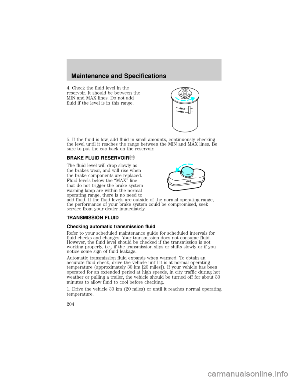
4. Check the fluid level in the
reservoir. It should be between the
MIN and MAX lines. Do not add
fluid if the level is in this range.
5. If the fluid is low, add fluid in small amounts, continuously checking
the level until it reaches the range between the MIN and MAX lines. Be
sure to put the cap back on the reservoir.
BRAKE FLUID RESERVOIR
The fluid level will drop slowly as
the brakes wear, and will rise when
the brake components are replaced.
Fluid levels below the ªMAXº line
that do not trigger the brake system
warning lamp are within the normal
operating range, there is no need to
add fluid. If the fluid levels are outside of the normal operating range,
the performance of your brake system could be compromised, seek
service from your dealer immediately.
TRANSMISSION FLUID
Checking automatic transmission fluid
Refer to your scheduled maintenance guide for scheduled intervals for
fluid checks and changes. Your transmission does not consume fluid.
However, the fluid level should be checked if the transmission is not
working properly, i.e., if the transmission slips or shifts slowly or if you
notice some sign of fluid leakage.
Automatic transmission fluid expands when warmed. To obtain an
accurate fluid check, drive the vehicle until it is at normal operating
temperature (approximately 30 km [20 miles]). If your vehicle has been
operated for an extended period at high speeds, in city traffic during hot
weather or pulling a trailer, the vehicle should be turned off for about 30
minutes to allow fluid to cool before checking.
1. Drive the vehicle 30 km (20 miles) or until it reaches normal operating
temperature.
DONOTOVERFILLPOWERSTEERINGFLUID
MAX
MIN
MAX
Maintenance and Specifications
204
Page 221 of 232

A
ABS (see Brakes) .....................126
Air bag supplemental
restraint system ................104, 108
and child safety seats ............106
description ......................104, 108
disposal ....................................111
driver air bag ..................106, 109
indicator light ...........12, 108, 110
operation .........................106, 109
passenger air bag ...........106, 109
side air bag ..............................108
Air cleaner filter ...............206, 211
Air conditioning ..........................33
Air suspension ...........................130
description ..............................130
warning light .............................13
Antifreeze
(see Engine coolant) ................188
Anti-lock brake system
(see Brakes) ......................126±127
Audio system
(see Radio) ..................................19
Automatic transmission
driving an automatic
overdrive .................................132
fluid, adding ............................204
fluid, checking ........................204
fluid, refill capacities ..............211
fluid, specification ..................214
Auxiliary power point .................59
Axle
lubricant
specifications ..................212, 214
refill capacities ........................211B
Battery .......................................186
acid, treating emergencies .....186
charging system warning
light ............................................12
jumping a disabled battery ....156
maintenance-free ....................186
replacement, specifications ...211
servicing ..................................186
voltage gauge ............................16
BeltMinder ...................................99
Brakes ........................................126
anti-lock ...........................126±127
anti-lock brake system (ABS)
warning light .....................12, 127
brake warning light ..................11
fluid, checking and adding ....204
fluid, refill capacities ..............211
fluid, specifications .........212, 214
lubricant
specifications ..................212, 214
shift interlock ..........................131
Bulbs ............................................43
C
Capacities for refilling fluids ....211
CD changer .................................28
CD-single premium .....................19
Cell phone use ............................73
Certification Label ....................216
Changing a tire .........................151
Child safety restraints ..............111
child safety belts ....................111
Index
221