battery Mercury Mercury Cougar 2002 Owner's Manual
[x] Cancel search | Manufacturer: MERCURY, Model Year: 2002, Model line: Mercury Cougar, Model: Mercury Mercury Cougar 2002Pages: 216, PDF Size: 4.04 MB
Page 3 of 216

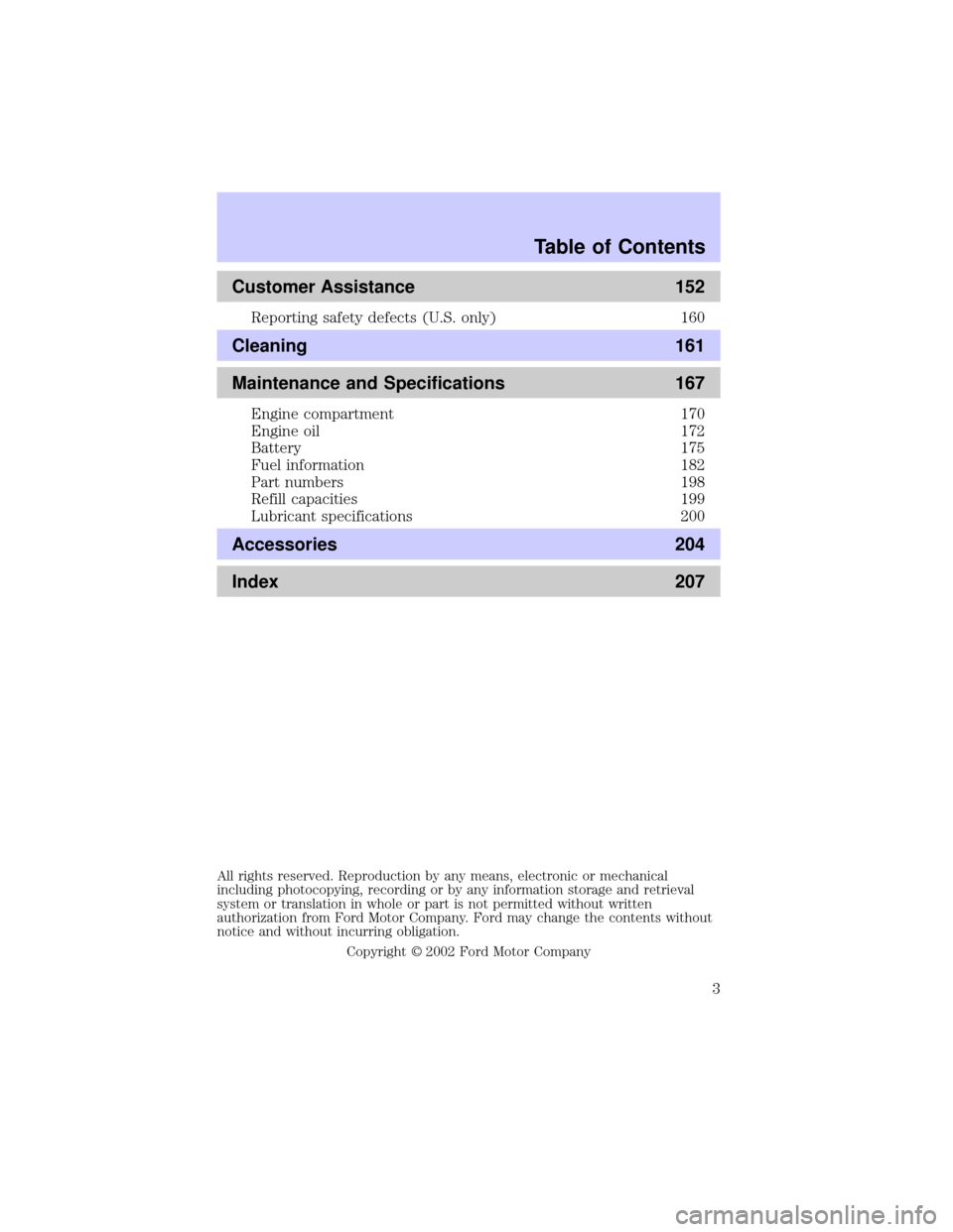
Customer Assistance 152
Reporting safety defects (U.S. only) 160
Cleaning 161
Maintenance and Specifications 167
Engine compartment 170
Engine oil 172
Battery 175
Fuel information 182
Part numbers 198
Refill capacities 199
Lubricant specifications 200
Accessories 204
Index 207
All rights reserved. Reproduction by any means, electronic or mechanical
including photocopying, recording or by any information storage and retrieval
system or translation in whole or part is not permitted without written
authorization from Ford Motor Company. Ford may change the contents without
notice and without incurring obligation.
Copyright 2002 Ford Motor Company
Table of Contents
3
Page 9 of 216

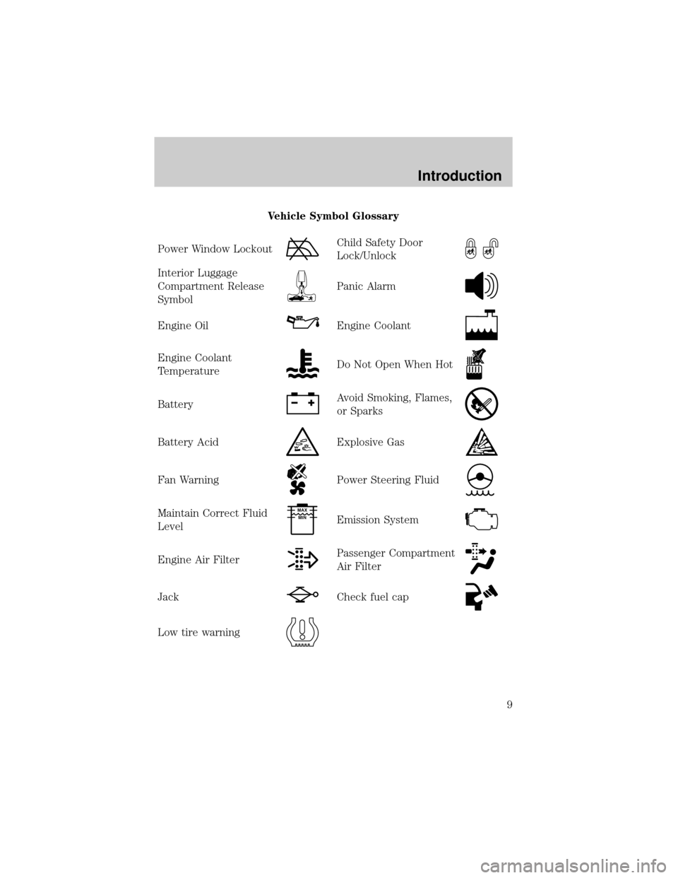
Vehicle Symbol Glossary
Power Window Lockout
Child Safety Door
Lock/Unlock
Interior Luggage
Compartment Release
Symbol
Panic Alarm
Engine OilEngine Coolant
Engine Coolant
TemperatureDo Not Open When Hot
BatteryAvoid Smoking, Flames,
or Sparks
Battery AcidExplosive Gas
Fan WarningPower Steering Fluid
Maintain Correct Fluid
LevelMAX
MIN
Emission System
Engine Air FilterPassenger Compartment
Air Filter
JackCheck fuel cap
Low tire warning
Introduction
9
Page 12 of 216

Safety belt
Illuminates to remind you to fasten
your safety belts. For more
information, refer to theSeating
and safety restraintschapter.
Air bag readiness
Illuminates to confirm that the air
bags (front and side) are
operational. If the light fails to
illuminate, continues to flash or
remains on, have the system
serviced immediately.
Charging system
Illuminates when the battery is not
charging properly.
Engine oil pressure
Illuminates when the oil pressure
falls below the normal range. Check
the oil level and add oil if needed.
Refer toEngine oilin the
Maintenance and specificationschapter.
Check coolant (if equipped)
Illuminates when the coolant level in
the coolant reservoir is low and
more needs to be added. For more
information on adding engine
coolant, refer toEngine coolantin
theMaintenance and specificationschapter.
Check transaxle
Illuminates when a transaxle
problem has been detected and
shifting may be restricted. If this
lamp remains on, have your vehicle
serviced immediately.
Instrument Cluster
12
Page 139 of 216

Fuse/Relay
LocationFuse Amp
RatingPassenger Compartment Fuse
Panel Description
30 7.5A Engine management, Locking
system, Instrument cluster
31 7.5A Panel dimmer, License plate
lamps, Glove box lamp, Belt
minder module
32 Ð Not used
33 7.5A Left-side lamps
34 7.5A Power mirrors, Clock, Interior
lamps
35 7.5A Right-side lamps
36 15A Radio
37 30A Heater blower
38 7.5A Air bags
R12 Ð Courtesy lamps
R13 Ð Rear window defrost
R14 Ð Blower motor
R15 Ð Front wiper
R16 Ð Ignition
D2 Ð Reverse voltage protection
*Have these fuses replaced by your dealer or qualified technician.
Power distribution box
The power distribution box is located in the engine compartment. The
power distribution box contains high-current fuses that protect your
vehicle's main electrical systems from overloads.
Always disconnect the battery before servicing high current
fuses.
Always replace the cover to the power distribution box before
reconnecting the battery or refilling fluid reservoirs
If the battery has been disconnected and reconnected, refer to the
Batterysection of theMaintenance and specificationschapter.
Roadside Emergencies
139
Page 145 of 216

4. Insert the tapered end of the jack
handle beneath the hub cover (if
equipped) and push in. Twist off to
remove the cover. Loosen each
wheel lug nut one-half turn
counterclockwise but do not remove
them until the wheel is raised off
the ground.
5. Place the jack under vehicle in
location indicated by arrows (closest
to the tire requiring changing), then
jack up the vehicle until the tire is
clear of the ground.
6. Remove the lug nuts with the lug wrench.
7. Replace the flat tire with the spare tire, making sure the valve stem is
facing outward. Reinstall the lug nuts until the wheel is snug against the
hub. Do not fully tighten the lug nuts until the wheel has been lowered.
8. Lower the wheel by turning the jack handle counterclockwise.
9. Remove the jack and fully tighten the lug nuts in the order shown.
10. Put flat tire, jack and lug wrench away. Make sure the jack is
fastened so it does not rattle when you drive. Unblock the wheels.
JUMP STARTING YOUR VEHICLE
The gases around the battery can explode if exposed to flames,
sparks, or lit cigarettes. An explosion could result in injury or
vehicle damage.
Batteries contain sulfuric acid which can burn skin, eyes and
clothing, if contacted.
Do not attempt to push-start your vehicle. Automatic
transmissions do not have push-start capability; also, the
catalytic converter may become damaged.
Roadside Emergencies
145
Page 146 of 216

Preparing your vehicle
When the battery is disconnected or a new battery is installed, the
transmission must relearn its shift strategy. As a result, the transmission
may have firm and/or soft shifts. This operation is considered normal and
will not affect function or durability of the transmission. Over time, the
adaptive learning process will fully update transmission operation.
1.Use only a 12±volt supply to start your vehicle.
2. Do not disconnect the battery of the disabled vehicle as this could
damage the vehicle's electrical system.
3. Park the booster vehicle close to the hood of the disabled vehicle
making sure the two vehiclesdo nottouch. Set the parking brake on
both vehicles and stay clear of the engine cooling fan and other moving
parts.
4. Check all battery terminals and remove any excessive corrosion before
you attach the battery cables. Ensure that vent caps are tight and level.
5. Turn the heater fan on in both vehicles to protect any electrical
surges. Turn all other accessories off.
Connecting the jumper cables
1. Connect the positive (+) booster cable to the positive (+) terminal of
the discharged battery.
Note:In the illustrations,lightning boltsare used to designate the
assisting (boosting) battery.
+–+–
Roadside Emergencies
146
Page 147 of 216

2. Connect the other end of the positive (+) cable to the positive (+)
terminal of the assisting battery.
3. Connect the negative (-) cable to the negative (-) terminal of the
assisting battery.
+–+–
+–+–
Roadside Emergencies
147
Page 148 of 216

4. Make the final connection of the negative (-) cable to an exposed
metal part of the stalled vehicle's engine, away from the battery and the
carburetor/fuel injection system.Do notuse fuel lines, engine rocker
covers or the intake manifold asgroundingpoints.
Do not connect the end of the second cable to the negative (-)
terminal of the battery to be jumped. A spark may cause an
explosion of the gases that surround the battery.
5. Ensure that the cables are clear of fan blades, belts, moving parts of
both engines, or any fuel delivery system parts.
Jump starting
1. Start the engine of the booster vehicle and run the engine at
moderately increased speed.
2. Start the engine of the disabled vehicle.
3. Once the disabled vehicle has been started, run both engines for an
additional three minutes before disconnecting the jumper cables.
+–+–
Roadside Emergencies
148
Page 149 of 216

Removing the jumper cables
Remove the jumper cables in the reverse order that they were
connected.
1. Remove the jumper cable from thegroundmetal surface.
Note:In the illustrations,lightning boltsare used to designate the
assisting (boosting) battery.
2. Remove the jumper cable on the negative (-) connection of the
booster vehicle's battery.
+–+–
+–+–
Roadside Emergencies
149
Page 150 of 216

3. Remove the jumper cable from the positive (+) terminal of the booster
vehicle's battery.
4. Remove the jumper cable from the positive (+) terminal of the
disabled vehicle's battery.
After the disabled vehicle has been started and the jumper cables
removed, allow it to idle for several minutes so the engine computer can
relearnits idle conditions.
+–+–
+–+–
Roadside Emergencies
150