instrument cluster Mercury Mountaineer 2002 Owner's Manuals
[x] Cancel search | Manufacturer: MERCURY, Model Year: 2002, Model line: Mountaineer, Model: Mercury Mountaineer 2002Pages: 312, PDF Size: 3.02 MB
Page 6 of 312

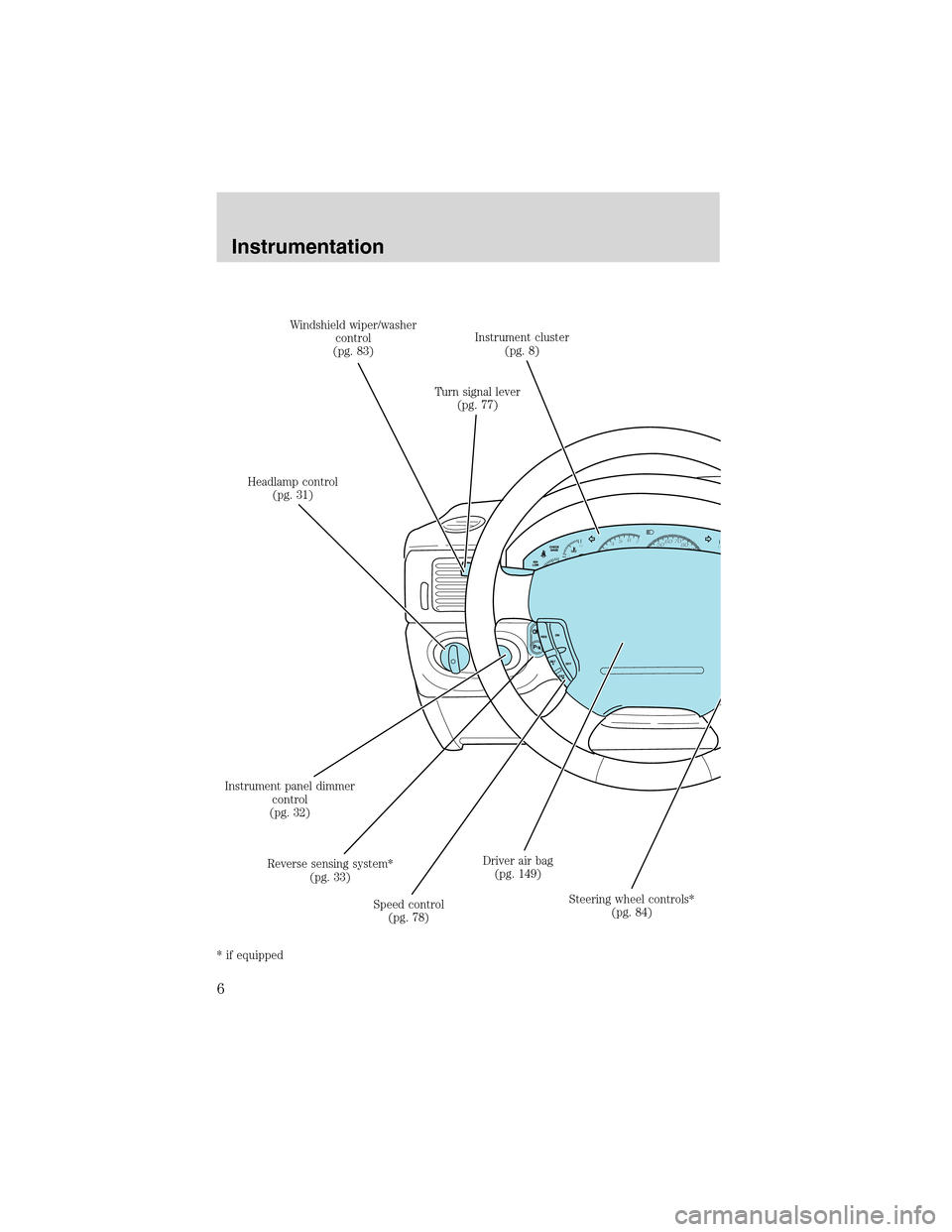
Headlamp control
(pg. 31)Windshield wiper/washer
control
(pg. 83)
Turn signal lever
(pg. 77)Instrument cluster
(pg. 8)
Steering wheel controls*
(pg. 84) Driver air bag
(pg. 149)
Speed control
(pg. 78) Reverse sensing system*
(pg. 33) Instrument panel dimmer
control
(pg. 32)
* if equipped
Instrumentation
6
Page 8 of 312

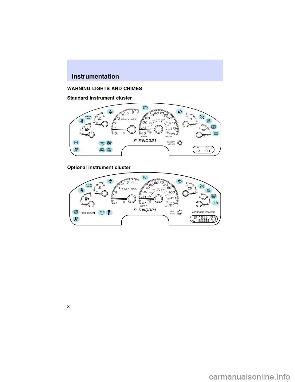
WARNING LIGHTS AND CHIMES
Standard instrument cluster
Optional instrument cluster
O/D
OFF
DOOR
AJARCHECK
GAGE
CHECK
FUEL
CAPLOW
WASH
BRAKE
SERVICE
ENGINE
SOON
TRIP
O/D
OFF
BRAKE
SERVICE
ENGINE
SOON
HI TEMP
LOW OIL
Instrumentation
8
Page 14 of 312

GAUGES
Standard instrument cluster gauges
Optional instrument cluster gauges
Speedometer
Indicates the current vehicle speed.
O/D
OFF
DOOR
AJARCHECK
GAGE
CHECK
FUEL
CAPLOW
WASH
BRAKE
SERVICE
ENGINE
SOON
TRIP
O/D
OFF
BRAKE
SERVICE
ENGINE
SOON
HI TEMP
LOW OIL
Instrumentation
14
Page 15 of 312

Engine coolant temperature gauge
Indicates the temperature of the
engine coolant. At normal operating
temperature, the needle remains
within the normal area (the
indicated area between the“H”and
“C”). If it enters the red section, the
engine is overheating. Stop the
vehicle as soon as safely possible,
switch off the engine immediately
and let the engine cool. Refer to
Engine coolantin theMaintenance and carechapter.
Never remove the coolant reservoir cap while the engine is
running or hot. Steam and scalding liquid from a hot cooling
system can burn you badly.
This gauge indicates the temperature of the engine coolant, not the
coolant level. If the coolant is not at its proper level the gauge indication
will not be accurate.
Odometer
Registers the total kilometers (miles) of the vehicle.
•Standard instrument cluster
•Optional instrument cluster
Refer toMessage Centerin this section for information on how to switch
the display from metric to English measurements.
TRIP
Instrumentation
15
Page 16 of 312

Tripodometer
Registers the kilometers (miles) of individual journeys.
•Standard instrument cluster
Press and release the
SELECT/RESET button to toggle
between the odometer and trip
odometer display. Press and hold
the button to reset.
•Optional instrument cluster
Press and release the TRIP/RESET
button to toggle between the
odometer and trip odometer display.
Press and hold the button to reset.
Tachometer
Indicates the engine speed in
revolutions per minute.
Driving with your tachometer
pointer in the red zone may damage
the engine.
Battery voltage gauge
Indicates battery voltage. If the
pointer moves and stays outside the
normal operating range, have the
vehicle’s electrical system checked
as soon as possible.
TRIP
Instrumentation
16
Page 17 of 312

Engineoil pressure gauge
Indicates engine oil pressure. At
normal operating temperature, the
needle will be in the normal range
(the area between the“L”and“H”);
if the needle goes below the normal
range, stop the vehicle as soon as
safely possible and switch off the
engine immediately. Check the oil
level. Add oil if needed (refer to
Engine oilin theMaintenance
and carechapter). If the oil level is correct, have your vehicle checked
at your dealership or by a qualified technician.
Fuel gauge
Displays approximately how much
fuel is in the fuel tank. The fuel
gauge may vary slightly when the
vehicle is in motion or on a grade.
When refueling the vehicle from
empty indication, the amount of fuel
that can be added will be less than
the advertised capacity due to the
reserve fuel.
The FUEL DOOR icon and arrow indicates which side of the vehicle the
fuel filler door is located.
ELECTRONIC COMPASS/TEMPERATURE DISPLAY (IF EQUIPPED)
OUTSIDE AIR TEMPERATURE
The outside temperature display is
contained in the instrument cluster
and displays all the time. If
equipped with the DEATC climate
control system, the outside
temperature will be displayed there.
To turn the display off or change the display from English to metric see
your dealer.
Compass
The compass reading may be affected when you drive near large
buildings, bridges, power lines and powerful broadcast antennas.
Magnetic or metallic objects placed in, on or near the vehicle may also
affect compass accuracy.
Instrumentation
17
Page 18 of 312

Usually, when something affects the compass readings, the compass will
correct itself after a few days of operating your vehicle in normal
conditions. If the compass still appears to be inaccurate, a manual
calibration may be necessary. Refer toCompass calibration
adjustment.
Most geographic areas (zones) have a magnetic north compass point that
varies slightly from the northerly direction on maps. This variation is four
degrees between adjacent zones and will become noticeable as the
vehicle crosses multiple zones. A correct zone setting will eliminate this
error. Refer toCompass zone adjustment.
Compass zone adjustment
1. Determine which magnetic zone
you are in for your geographic
location by referring to the zone
map.
2. Turn ignition to the ON position.
3. Locate compass sensor mounted
at base of mirror.
4. Insert a paperclip into the small
hole on the bottom of the compass
sensor or press the button on the
top of the compass module until
ZONE appears in the instrument cluster display.
5. Release pressure on the paperclip or button and then slowly press it
down again.
6. Continue to press until ZONE
appears in the instrument cluster
display, then release. The display
should show the current zone
number.
7. Press until the desired zone
number appears. The display will flash and then return to normal
operation. The zone is now updated.
1 2 3
4
5
6 7 8 9 101112 13 14 15
Instrumentation
18
Page 19 of 312

Compasscalibrationadjustment
Perform this adjustment in an open area free from steel structures and
high voltage lines:
For optimum calibration, turn off all electrical accessories (heater/air
conditioning, wipers, etc.) and make sure all vehicle doors are shut.
1. Start the vehicle.
2. Locate compass sensor mounted at base of mirror.
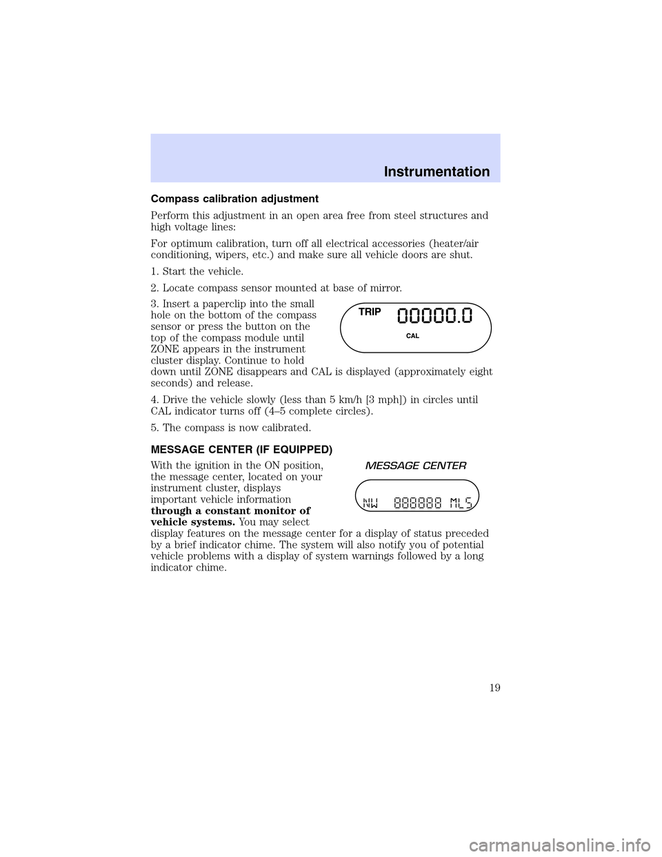
3. Insert a paperclip into the small
hole on the bottom of the compass
sensor or press the button on the
top of the compass module until
ZONE appears in the instrument
cluster display. Continue to hold
down until ZONE disappears and CAL is displayed (approximately eight
seconds) and release.
4. Drive the vehicle slowly (less than 5 km/h [3 mph]) in circles until
CAL indicator turns off (4–5 complete circles).
5. The compass is now calibrated.
MESSAGE CENTER (IF EQUIPPED)
With the ignition in the ON position,
the message center, located on your
instrument cluster, displays
important vehicle information
through a constant monitor of
vehicle systems.You may select
display features on the message center for a display of status preceded
by a brief indicator chime. The system will also notify you of potential
vehicle problems with a display of system warnings followed by a long
indicator chime.
Instrumentation
19
Page 134 of 312

common, moderate-severity impacts. A higher energy level is used for
the most severe impacts. Refer toAir bag Supplemental Restraints
section in this chapter.
Front crash severity sensor
The front crash severity sensor enhances the ability to detect the
severity of an impact. Positioned up front, it provides valuable
information early in the crash event on the severity of the impact. This
allows your Personal Safety System to distinguish between different
levels of crash severity and modify the deployment strategy of the
dual-stage air bags and safety belt pretensioners.
Driver’s seat position sensor
The driver’s seat position sensor allows your Personal Safety System to
tailor the deployment level of the driver dual-stage air bag based on seat
position. The system is designed to help protect smaller drivers sitting
close to the driver air bag by providing a lower air bag output level.
Front safety belt usage sensors
The front safety belt usage sensors detect whether or not the driver and
front outboard passenger safety belts are fastened. This information
allows your Personal Safety System to tailor the air bag deployment and
safety belt pretensioner activation depending upon safety belt usage.
Refer toSafety Beltsection in this chapter.
Front safety belt pretensioners
The safety belt pretensioners are designed to tighten the safety belts
firmly against the occupant’s body during a collision. This maximizes the
effectiveness of the safety belts and helps properly position the occupant
relative to the air bag to improve protection. The safety belt
pretensioners can be either activated alone or, if the collision is of
sufficient severity, together with the air bags.
Front safety belt energy management retractors
The front safety belt energy management retractors allow webbing to be
pulled out of the retractor in a gradual and controlled manner in
response to the occupant’s forward momentum. This helps reduce the
risk of force-related injuries to the occupant’s chest by limiting the load
on the occupant. Refer toSafety Beltsection in this chapter.
Determining if the Personal Safety System is operational
The Personal Safety System uses a warning light in the instrument
cluster or a back-up tone to indicate the condition of the system. Refer
Seating and safety restraints
134
Page 135 of 312

to theWarning Lightsection in theInstrument Clusterchapter.
Routine maintenance of the Personal Safety System is not required.
The Restraints Control Module (RCM) monitors its own internal circuits
and the circuits for the air bag supplemental restraints, crash sensor(s),
safety belt pretensioners, front safety belt buckle sensors, and the driver
seat position sensor. In addition, the RCM also monitors the restraints
warning light in the instrument cluster. A difficulty with the system is
indicated by one or more of the following:
•The warning light will either flash or stay lit.
•The warning light will not illuminate immediately after the ignition is
turned on.
•A series of five beeps will be heard. The tone pattern will repeat
periodically until the problem and warning light are repaired.
If any of these things happen, even intermittently, have the Personal
Safety System serviced at your dealership or by a qualified technician
immediately. Unless serviced, the system may not function properly in
the event of a collision.
Safety restraints precautions
Always drive and ride with your seatback upright and the lap
belt snug and low across the hips.
To reduce the risk of injury, make sure children sit where they
can be properly restrained.
Never let a passenger hold a child on his or her lap while the
vehicle is moving. The passenger cannot protect the child from
injury in a collision.
All occupants of the vehicle, including the driver, should always
properly wear their safety belts, even when an air bag (SRS) is
provided.
It is extremely dangerous to ride in a cargo area, inside or
outside of a vehicle. In a collision, people riding in these areas
are more likely to be seriously injured or killed. Do not allow people to
ride in any area of your vehicle that is not equipped with seats and
safety belts. Be sure everyone in your vehicle is in a seat and using a
safety belt properly.
Seating and safety restraints
135