battery location Mercury Mountaineer 2003 Owner's Manuals
[x] Cancel search | Manufacturer: MERCURY, Model Year: 2003, Model line: Mountaineer, Model: Mercury Mountaineer 2003Pages: 264, PDF Size: 2.5 MB
Page 168 of 264

The fuses are coded as follows:
Fuse/Relay
LocationFuse Amp
RatingPassenger Compartment Fuse
Panel Description
1 30A Memory seat module, Driver
power seat
2 20A Moonroof
3 20A Radio, Amplifier, DVD
4 5A Front wiper module
5 15A Flasher relay (Turn, hazards)
6 10A Right horn
7 15A Heated mirrors
8—Not used
9—Not used
10 10A Heated backlight relay coil, A/C
clutch contact
11 20A Heated seats
12—Not used
13 5A Overdrive cancel switch, Flex fuel
sender
14 5A PATS module
15 5A Rear wiper module, Cluster, TPMS
16 5A Power mirror, Manual climate
control, TPMS
17 15A Delayed acc. coil, Battery saver,
Glove compartment lamp, 2nd
row courtesy lamps, Interior
lamps (front)
18 10A Left horn
19 10A RCM
20 5A Driver seat switch, Driver seat
module, BSM, Sunload sensor
21 5A Instrument cluster, Compass,
Flasher coil
22 10A ABS
Roadside Emergencies
168
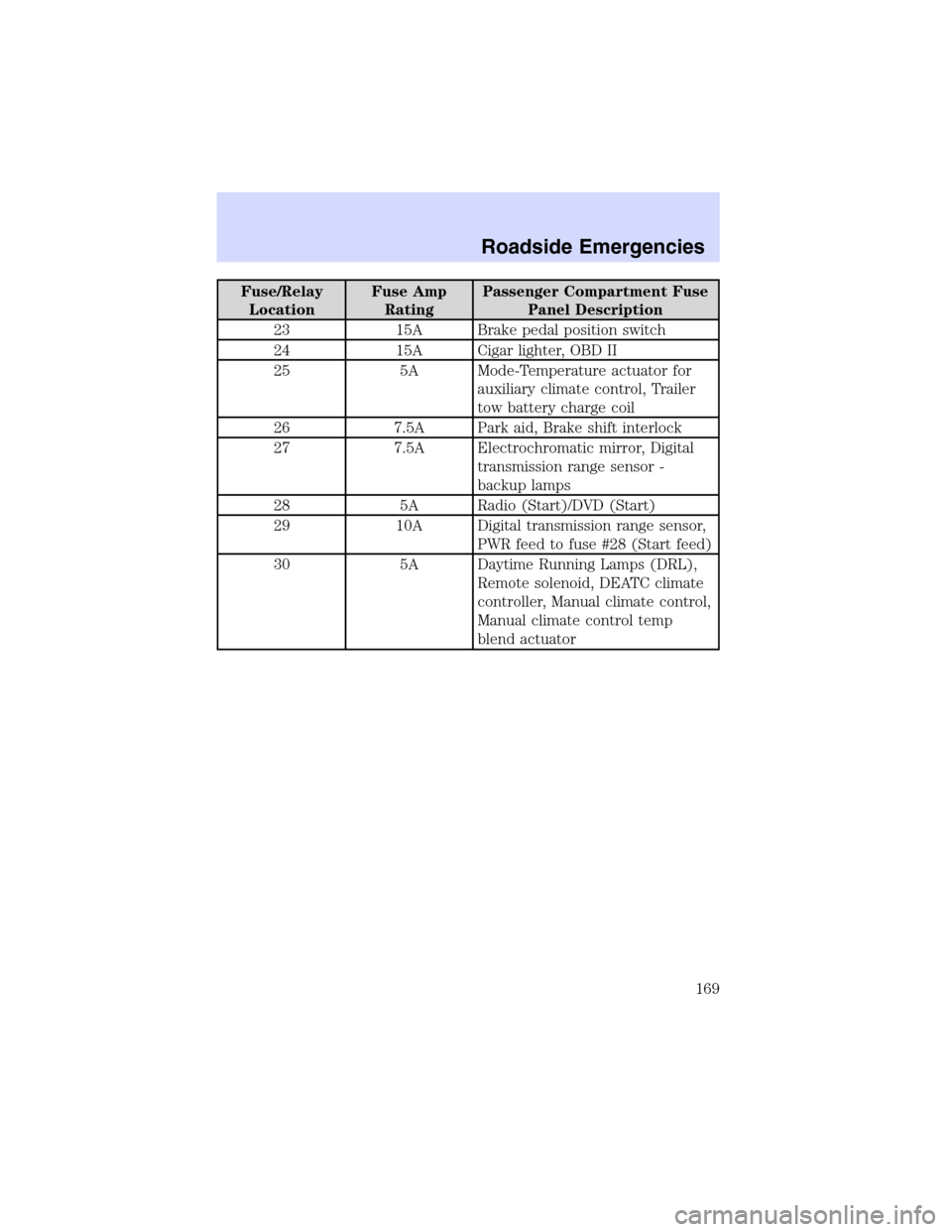
Page 169 of 264

Fuse/Relay
LocationFuse Amp
RatingPassenger Compartment Fuse
Panel Description
23 15A Brake pedal position switch
24 15A Cigar lighter, OBD II
25 5A Mode-Temperature actuator for
auxiliary climate control, Trailer
tow battery charge coil
26 7.5A Park aid, Brake shift interlock
27 7.5A Electrochromatic mirror, Digital
transmission range sensor -
backup lamps
28 5A Radio (Start)/DVD (Start)
29 10A Digital transmission range sensor,
PWR feed to fuse #28 (Start feed)
30 5A Daytime Running Lamps (DRL),
Remote solenoid, DEATC climate
controller, Manual climate control,
Manual climate control temp
blend actuator
Roadside Emergencies
169
Page 170 of 264

Passenger compartment fuse panel (top side)
These relays are located on the reverse side of the passenger
compartment fuse panel. See your dealer or a certified technician for
service of this relay box.
Fuse/Relay Location Description
Relay 1 Flasher relay
Relay 2 Rear defrost
Relay 3 Delayed accessory relay
Relay 4 Open
Relay 5 Battery saver
Relay 6 Open
Relay 7 Open
Roadside Emergencies
170
Page 172 of 264

The high-current fuses are coded as follows:
Fuse/Relay
LocationFuse Amp
RatingPower Distribution Box
Description
1 60A** PJB
2 30A** BSM
3—Not used
4 30A** Rear defrost
5 40A** Anti-lock Brake System (ABS)
pump
6 60A** Delayed accessory
7 20A** Power point #2
8—Not used
9 20A** Power point #1
10 30A** ABS module (valves)
11 40A** PTEC
12 50A** Ignition relay, Starter relay
13 40A** Trailer tow battery, Trailer tow
turn signals
14 10A* Daytime Running Lamps (DRL)
(Canada)
15 15A* Memory (PCM/DEATC/Cluster),
Interior lights
16 15A* Headlamp switch, Foglamp switch
17—Not used
18—Not used
19 20A** High beam relay
20 30A** Electric brake
21 30A** Front wiper motor
22 20A** Low beam
23 30A** Ignition switch
24—Not used
25—Not used
26 15A* Fuel pump
Roadside Emergencies
172
Page 175 of 264

Fuse/Relay Location Description
Relay 20 Trailer tow battery charge
Relay 21 Not used
Relay 22 Not used
Relay 23 Not used
Diode 3 Not used
Diode 4 Not used
Auxiliary relay box
The relay box is located on the front
right fender well underneath the
speed control module.
The relays are coded as follows:
Fuse/Relay Location Description
Relay 64 Open
Relay 65 Open
Relay 66 Open
Roadside Emergencies
175
Page 183 of 264

ability, to the point where the ratchet/slip occurs, if possible. The spare
tire carrier will not allow you to overtighten. If the spare tire carrier
ratchets or slips with little effort, take the vehicle to your dealer for
assistance at your earliest convenience.
4. Check that the tire lies flat against the frame and is properly
tightened. Try to push or pull, then turn the tire to be sure it will not
move. Loosen and retighten, if necessary. Failure to properly stow the
spare tire may result in failure of the winch cable and loss of the tire.
5. If your vehicle is equipped with a spare tire lock and key, be sure to
install the spare tire lock into the bumper drive tube with the spare tire
lock key and jack handle.
6. Repeat this tightness check procedure when servicing the spare tire
pressure (every six months, per scheduled maintenance guide), or at any
time that the spare tire is disturbed through service of other
components.
Re-stowing the jack and tools
1. Unblock the wheels.
2. Replace beauty cap, stow the jack and tools in their respective
locations, making sure they are fully secured so they do not rattle when
you drive.
JUMP STARTING YOUR VEHICLE
The gases around the battery can explode if exposed to flames,
sparks, or lit cigarettes. An explosion could result in injury or
vehicle damage.
Batteries contain sulfuric acid which can burn skin, eyes and
clothing, if contacted.
Do not attempt to push-start your vehicle. Automatic
transmissions do not have push-start capability; also, the
catalytic converter may become damaged.
Roadside Emergencies
183