glove box Mercury Mountaineer 2004 Owner's Manuals
[x] Cancel search | Manufacturer: MERCURY, Model Year: 2004, Model line: Mountaineer, Model: Mercury Mountaineer 2004Pages: 280, PDF Size: 5.38 MB
Page 85 of 280

Illuminated entry
The interior lamps illuminate when the remote entry system is used to
unlock the door(s) or sound the personal alarm.
The illuminated entry system will turn off the interior lights if:
•the ignition is turned to the 3 (ON) position, or
•the remote transmitter lock control is pressed, or
•after 25 seconds of illumination.
The dome lamp control (if equipped) mustnotbe set to theoffposition
for the illuminated entry system to operate.
The inside lights will not turn off if:
•they have been turned on with the dimmer control, or
•any door is open.
The battery saver will shut off the interior lamps 10 minutes after the
ignition has been turned to the 1 (OFF/LOCK) position.
KEYLESS ENTRY SYSTEM (IF EQUIPPED)
You can use the keyless entry
keypad to:
•lock or unlock the doors without
using a key.
•open the liftgate window.
•activate or deactivate the
autolock feature.
The keypad can be operated with
the factory set 5–digit entry code;
this code is located on the owner’s
wallet card in the glove box, is
marked on the computer module,
and is available from your
authorized dealer. You can also
create your own 5–digit personal
entry code.
When pressing the controls on the keypad, press the middle of the
controls to ensure a good activation.
Programming a personal entry code
To create your own personal entry code:
1. Enter the factory set code.
2004 Mountaineer(mnt)
Owners Guide (post-2002-fmt)
USA English(fus)
Locks and Security
85
Page 178 of 280

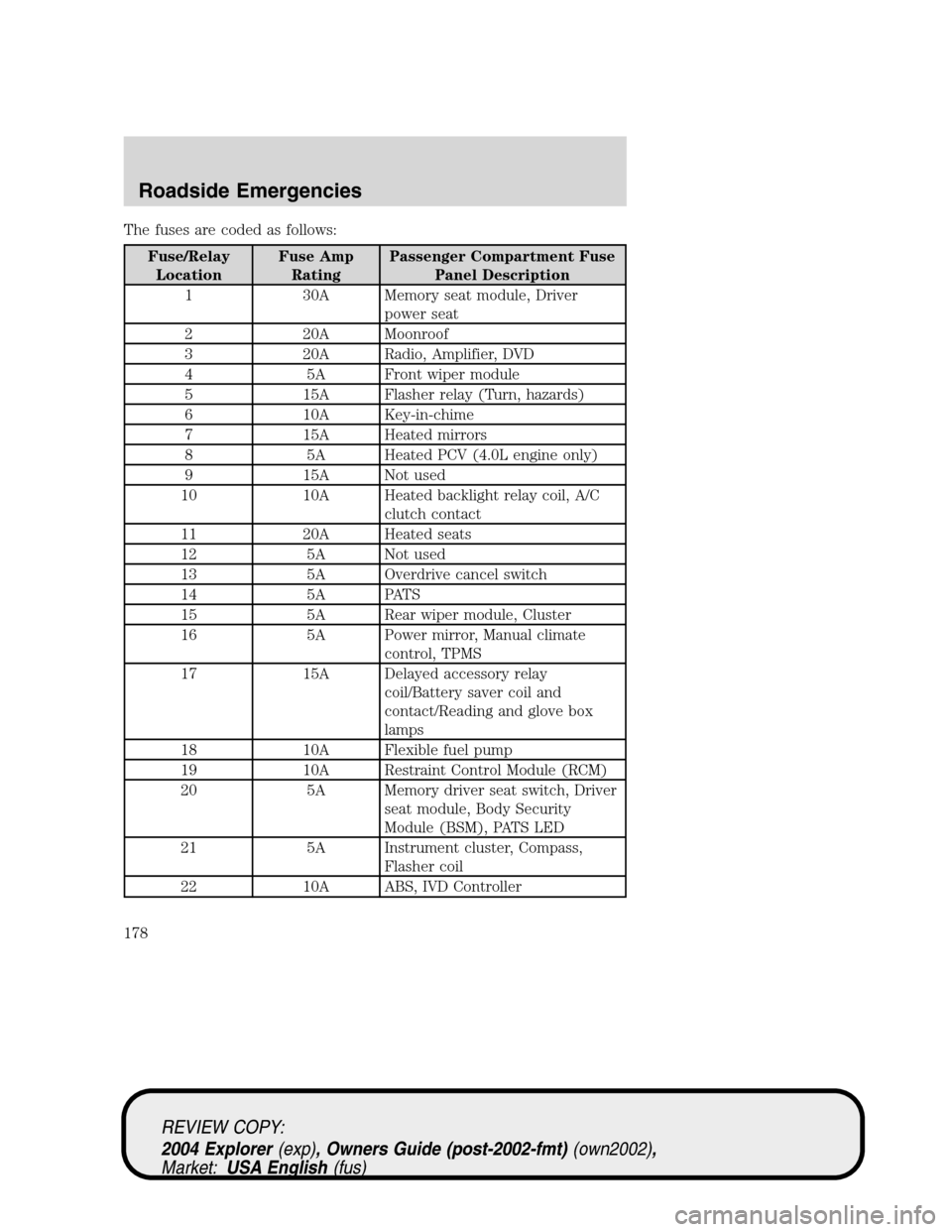
The fuses are coded as follows:
Fuse/Relay
LocationFuse Amp
RatingPassenger Compartment Fuse
Panel Description
1 30A Memory seat module, Driver
power seat
2 20A Moonroof
3 20A Radio, Amplifier, DVD
4 5A Front wiper module
5 15A Flasher relay (Turn, hazards)
6 10A Key-in-chime
7 15A Heated mirrors
8 5A Heated PCV (4.0L engine only)
9 15A Not used
10 10A Heated backlight relay coil, A/C
clutch contact
11 20A Heated seats
12 5A Not used
13 5A Overdrive cancel switch
14 5A PATS
15 5A Rear wiper module, Cluster
16 5A Power mirror, Manual climate
control, TPMS
17 15A Delayed accessory relay
coil/Battery saver coil and
contact/Reading and glove box
lamps
18 10A Flexible fuel pump
19 10A Restraint Control Module (RCM)
20 5A Memory driver seat switch, Driver
seat module, Body Security
Module (BSM), PATS LED
21 5A Instrument cluster, Compass,
Flasher coil
22 10A ABS, IVD Controller
REVIEW COPY:
2004 Explorer(exp), Owners Guide (post-2002-fmt)(own2002),
Market:USA English(fus)
Roadside Emergencies
178
Page 194 of 280

ability, to the point where the ratchet/slip occurs, if possible. The spare
tire carrier will not allow you to overtighten. If the spare tire carrier
ratchets or slips with little effort, take the vehicle to your dealer for
assistance at your earliest convenience.
4. Check that the tire lies flat against the frame and is properly
tightened. Try to push or pull, then turn the tire to be sure it will not
move. Loosen and retighten, if necessary. Failure to properly stow the
spare tire may result in failure of the winch cable and loss of the tire.
5. If your vehicle is equipped with a spare tire lock and key, be sure to
install the spare tire lock into the bumper drive tube with the spare tire
lock key and jack handle.
6. Repeat this tightness check procedure when servicing the spare tire
pressure (every six months, perScheduled Maintenance Guide), or at any
time that the spare tire is disturbed through service of other components.
Re-stowing the jack and tools
1. Unblock the wheels.
2. Stow the wheel ornament (if removed) in a safe location in the vehicle
(such as the glove box or jack stowage compartment) so it will not
become damaged. Re-install the wheel ornament onto the wheel once the
tire is repaired or replaced.
3. Stow the jack and tools in their respective locations, making sure they
are fully secured so they do not rattle when you drive.
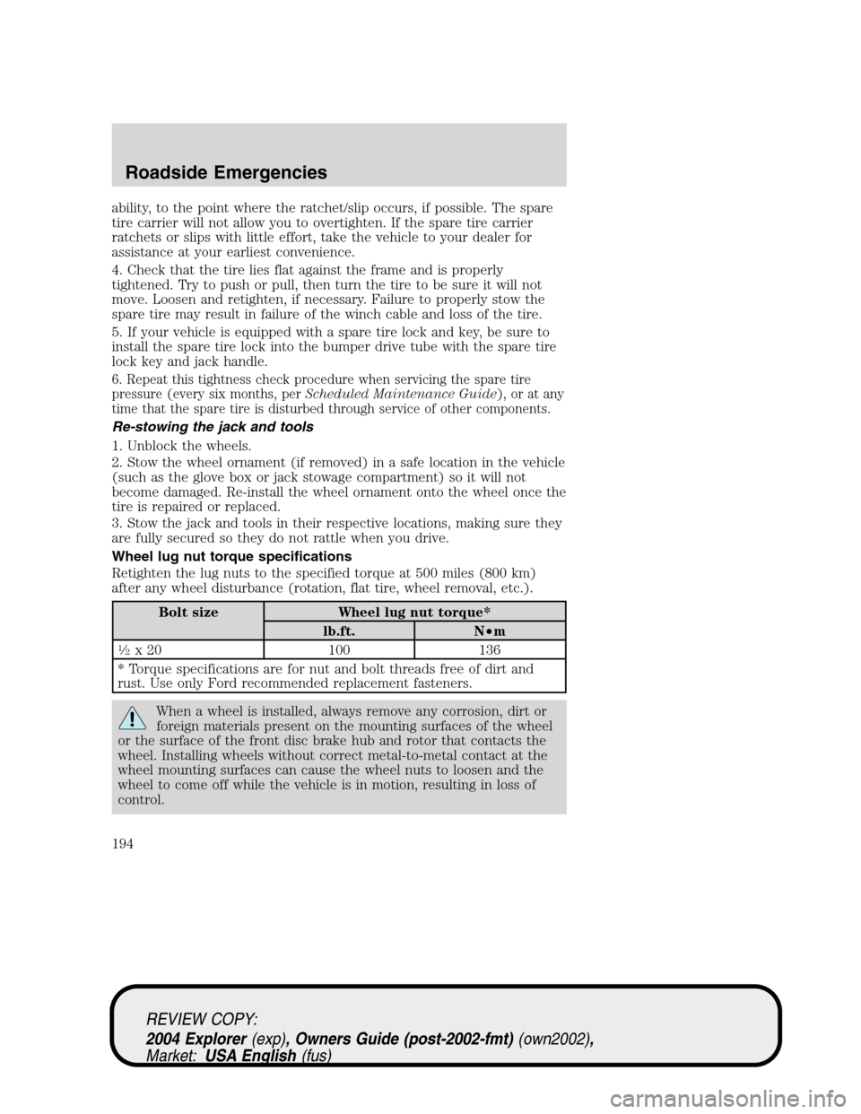
Wheel lug nut torque specifications
Retighten the lug nuts to the specified torque at 500 miles (800 km)
after any wheel disturbance (rotation, flat tire, wheel removal, etc.).
Bolt size Wheel lug nut torque*
lb.ft. N•m
1�2x 20 100 136
* Torque specifications are for nut and bolt threads free of dirt and
rust. Use only Ford recommended replacement fasteners.
When a wheel is installed, always remove any corrosion, dirt or
foreign materials present on the mounting surfaces of the wheel
or the surface of the front disc brake hub and rotor that contacts the
wheel. Installing wheels without correct metal-to-metal contact at the
wheel mounting surfaces can cause the wheel nuts to loosen and the
wheel to come off while the vehicle is in motion, resulting in loss of
control.
REVIEW COPY:
2004 Explorer(exp), Owners Guide (post-2002-fmt)(own2002),
Market:USA English(fus)
Roadside Emergencies
194