Mercury Sable 1998 Owner's Manuals
Manufacturer: MERCURY, Model Year: 1998, Model line: Sable, Model: Mercury Sable 1998Pages: 190, PDF Size: 1.29 MB
Page 111 of 190

The fuses are coded as follows.
Fuse/
Relay
LocationFuse
Amp
RatingDescription
1 Ð Not Used
2 5A Instrument Illumination
3 10A Left Low Beam Headlamp
4 10A Right Low Beam Headlamp
5 5A Brake Shift Interlock, Rear
Defrost
6 15A MLPS Switch, Backup Lamps,
Speed Control
7 10A MLPS Switch, Starter Relay
8 5A Power Antenna, RCU, GEM
9 10A ABS
10 20A PCM Relay, Ignition Coil,
PATS, Radio
11 5A Instrument Cluster
12 5A Instrument Cluster, Autolamps,
Transmission Control Switch,
ICP, GEM
13 5A Air Bag, Blower Motor, EATC
14 5A Air Suspension
15 10A Multi-Function Switch (Turn
Signal)
16 Ð Not Used
17 30A Front Wiper/Washer
18 5A Headlamp Switch
19 15A Rear Wiper/Washer
20 5A ICP, RAP, Phone
21 20A Cigar Lighter
22 5A Power Mirrors, Power
Antenna, Decklid Lamps,
Autolamp
Roadside emergencies
111
Page 112 of 190
Fuse/
Relay
LocationFuse
Amp
RatingDescription
23 5A GEM, RAP, PATS
24 5A ICP, RCC, Speedometer
25 10A Data Link Connector (DLC)
26 15A Trunklid
27 10A Battery Saver Relay
28 15A Speed Control, Stop Lamp
29 15A Multi-Function Switch, Hazard
30 15A High Beams, Daytime Running
Lamps, Instrument Cluster
31 Ð Not Used
32 10A ICP, Heated Mirrors
33 5A Power Windows, Lock
Illumination
34 Ð Battery Saver Relay
35 Ð Driver Door Unlock Relay
36 Ð Rear Defroster Relay
37 Ð Interior Lamp Relay
38 Ð One Touch Window Down
Relay
39 Ð Accessory Delay Relay
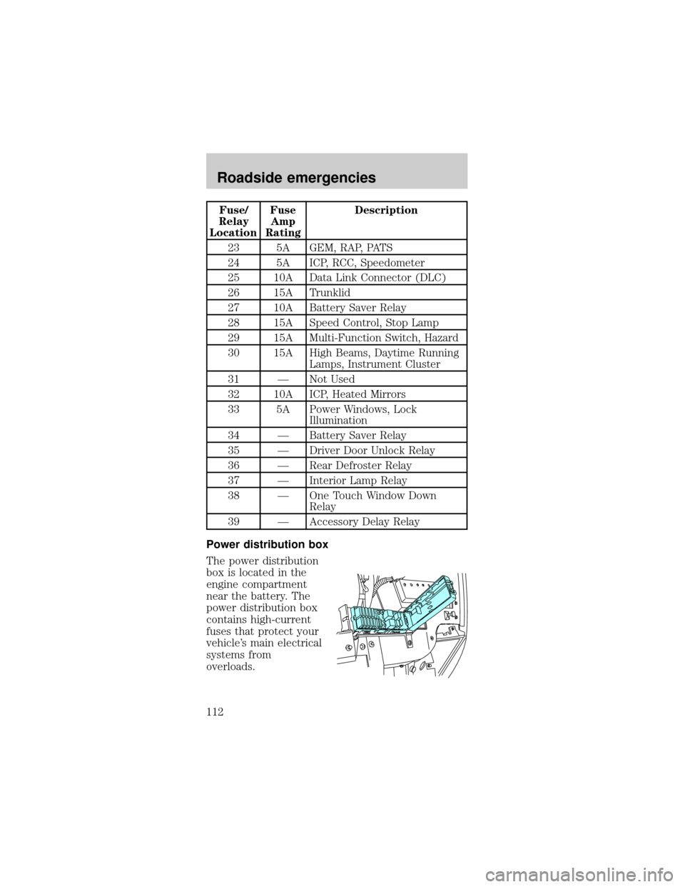
Power distribution box
The power distribution
box is located in the
engine compartment
near the battery. The
power distribution box
contains high-current
fuses that protect your
vehicle's main electrical
systems from
overloads.
Roadside emergencies
112
Page 113 of 190
Always disconnect the battery before
servicing high current fuses.
Always replace the cover to the Power
Distribution Box before reconnecting the
battery or refilling fluid reservoirs.
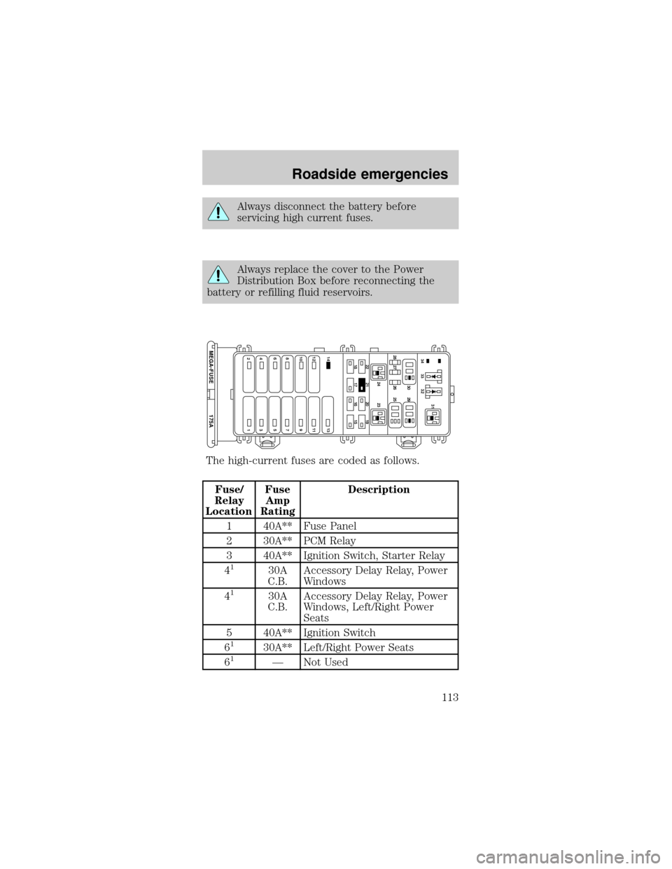
The high-current fuses are coded as follows.
Fuse/
Relay
LocationFuse
Amp
RatingDescription
1 40A** Fuse Panel
2 30A** PCM Relay
3 40A** Ignition Switch, Starter Relay
4
130A
C.B.Accessory Delay Relay, Power
Windows
4
130A
C.B.Accessory Delay Relay, Power
Windows, Left/Right Power
Seats
5 40A** Ignition Switch
6
130A** Left/Right Power Seats
61Ð Not Used
22
14 13
12 11
10 9
87
175A MEGA-FUSE
65
43
2121 24 23 28 27 26 2530 2931
33 3432
20 19
18 17 16 15
Roadside emergencies
113
Page 114 of 190

Fuse/
Relay
LocationFuse
Amp
RatingDescription
7 40A** Rear Window Defrost Relay
8 30A** Thermactor Air ByPass
Solenoid, EAM Solid State
Relay
9 40A** High Speed Cooling Fan Relay,
Low Speed Cooling Fan Relay
10 20A** Fuel Pump Relay
11 40A** Blower Motor Relay
12 Ð Not Used
13 40A** Anti-Lock Brake Module
14 Ð Not Used
15 15A* Daytime Running Lamps
(DRL) Module
16 10A* Air Bag Diagnostic Monitor
17 20A* Rear Control Unit, CD Changer
18 30A* Anti-Lock Brake Module
19 15A* Horn Relay, Powertrain Control
Module (PCM)
20 15A* Headlamp Switch, Autolamp
Park Relay
21 Ð Not Used
22 30A* Autolamps Relay,
Multi-Function Switch,
Headlamp Switch
23 Ð Blower Motor Relay
24 Ð Starter Relay
25 Ð A/C Clutch Relay
26 30A* Generator/Voltage Regulator
27 10A* A/C Clutch Relay
28 15A* Heated Oxygen Sensors,
Canister Vent
29 Ð Fuel Pump Relay
Roadside emergencies
114
Page 115 of 190
Fuse/
Relay
LocationFuse
Amp
RatingDescription
30 Ð PCM Relay
31 Ð Low Speed Cooling Fan Relay
32 Ð PCM Diode
33 Ð A/C Clutch Diode
34 Ð Not Used
* Mini Fuses ** Maxi Fuses
1Fuses 4 and 6 will vary depending on date of
vehicle build.
Relays
Relays are located in the power distribution box and
should be replaced by qualified technicians.
CHANGING THE TIRES
If you get a flat tire while driving, do not apply the
brake heavily. Instead, gradually decrease your
speed. Hold the steering wheel firmly and slowly
move to a safe place on the side of the road.
Temporary spare tire information
The temporary spare tire for your vehicle is labeled
as such. It is smaller than a regular tire and is
designed for emergency use only.
If you use the temporary spare tire
continuously or do not follow these
precautions, the tire could fail, causing you to lose
control of the vehicle, possibly injuring yourself or
others.
Roadside emergencies
115
Page 116 of 190
When driving with the temporary spare tiredo not:
²exceed 80 km/h (50 mph) under any
circumstances
²load the vehicle beyond maximum vehicle load
rating listed on the Safety Compliance Label
²tow a trailer
²use tire chains
²drive through an automatic car wash, because of
the vehicle's reduced ground clearance
²try to repair the temporary spare tire or remove it
from its wheel
²use the wheel for any other type of vehicle
Removing and replacing wheel covers
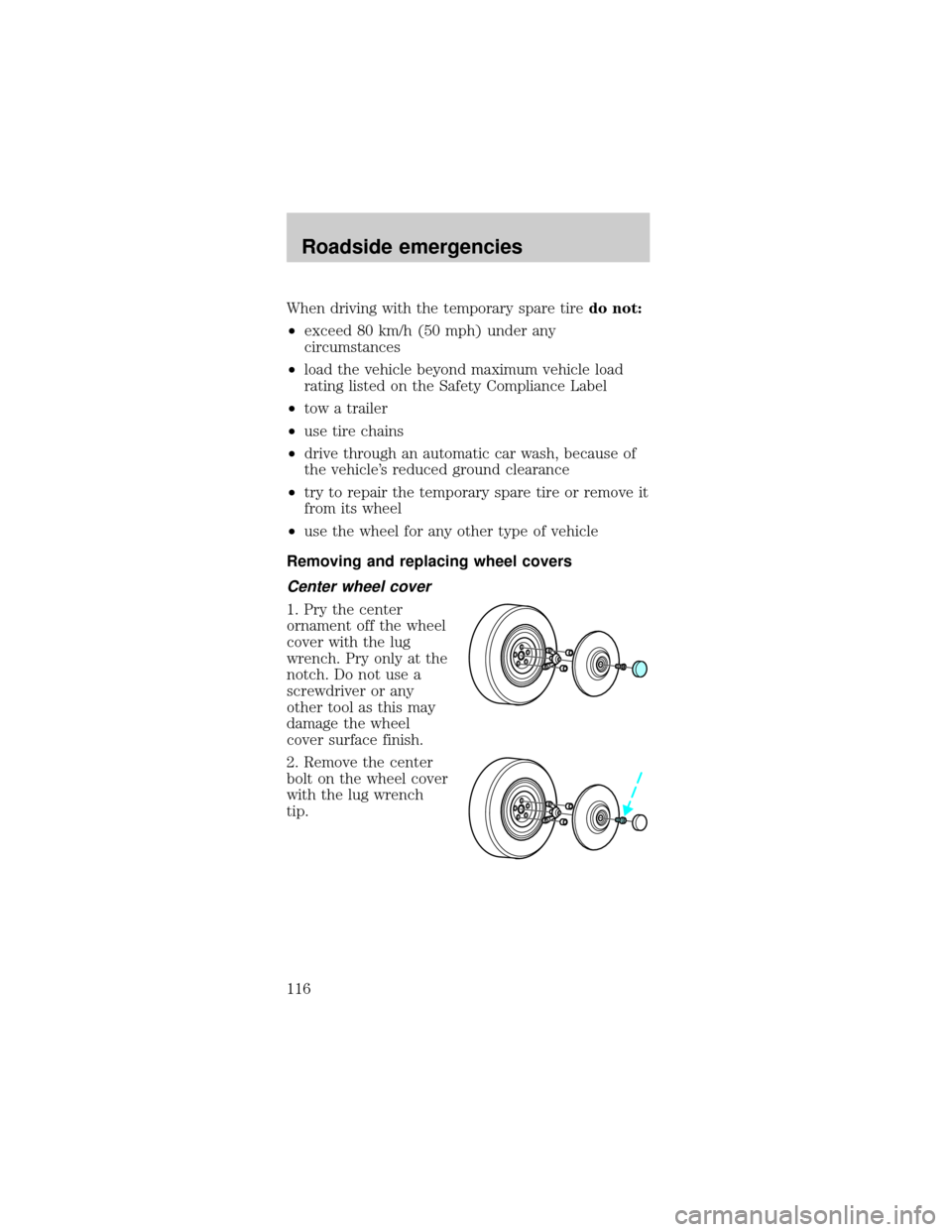
Center wheel cover
1. Pry the center
ornament off the wheel
cover with the lug
wrench. Pry only at the
notch. Do not use a
screwdriver or any
other tool as this may
damage the wheel
cover surface finish.
2. Remove the center
bolt on the wheel cover
with the lug wrench
tip.
Roadside emergencies
116
Page 117 of 190

3. To remove the wheel
cover, pry it loose by
inserting the tapered
end of the lug wrench
between the wheel
cover and wheel.
To replace the wheel cover:
1. One of the windows on the wheel cover is
identified with a valve stem logo on the back side of
the wheel cover. Install the wheel cover over the
wheel with the window at the valve stem.
2. Hold the wheel cover in this position and press
the cover onto the wheel with the palm of your
hand. Do not force or hammer the cover.
3. Attach the bolt to the pedestal through the center
hole on the cover with the lug wrench.
4. Align the legs of the center ornament with the
slots of the wheel cover. Reinstall the ornament by
pressing with the palm of your hand. Do not
hammer or force the cover.
Anti-theft lug nuts (if equipped)
If your vehicle is
equipped with this
feature, one of the lug
nuts on each wheel
must be removed and replaced with a special key.
The key and registration card are attached to the lug
wrench and stored with the spare tire. If you lose
the key, send the registration card to the
manufacturer (not the dealer) to get a replacement
key. If the lug wrench/lug nut key assembly is lost,
see your nearest Ford or Lincoln/Mercury dealer
who has access to the master set of keys.Do not
use an impact wrench with the anti-theft key.
Roadside emergencies
117
Page 118 of 190

Removing the anti-theft lug nut
1. Insert the key over the locking lug nut. Make sure
you hold the key square to the lug nut. If you hold
the key at an angle, you could damage the key and
the lug nut.
2. Place the lug nut wrench over the lug nut key and
apply pressure on the key with the wrench.
3. Turn the wrench in a counterclockwise direction
to remove the lug nut.
Reinstalling the anti-theft lug nut
1. Insert the key over the locking lug nut.
2. Place the lug nut wrench over the lug nut key and
apply pressure on the key with the wrench.
3. Install the lug nut.
Tire change procedure
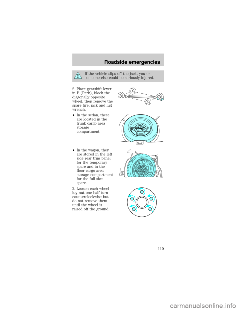
1. Park on a level surface, activate hazard flashers
and set parking brake.
When one of the front wheels is off the
ground, the transaxle alone will not prevent
the vehicle from moving or slipping off the jack,
even if the vehicle is in P (Park).
To prevent the vehicle from moving when
you change a tire, be sure the parking brake
is set, then block (in both directions) the wheel
that is diagonally opposite (other side and end of
the vehicle) to the tire being changed.
Roadside emergencies
118
Page 119 of 190
If the vehicle slips off the jack, you or
someone else could be seriously injured.
2. Place gearshift lever
in P (Park), block the
diagonally opposite
wheel, then remove the
spare tire, jack and lug
wrench.
²In the sedan, these
are located in the
trunk cargo area
storage
compartment.
²In the wagon, they
are stored in the left
side rear trim panel
for the temporary
spare and in the
floor cargo area
storage compartment
for the full size
spare.
3. Loosen each wheel
lug nut one-half turn
counterclockwise but
do not remove them
until the wheel is
raised off the ground.
Roadside emergencies
119
Page 120 of 190
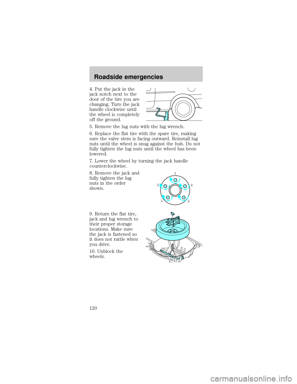
4. Put the jack in the
jack notch next to the
door of the tire you are
changing. Turn the jack
handle clockwise until
the wheel is completely
off the ground.
5. Remove the lug nuts with the lug wrench.
6. Replace the flat tire with the spare tire, making
sure the valve stem is facing outward. Reinstall lug
nuts until the wheel is snug against the hub. Do not
fully tighten the lug nuts until the wheel has been
lowered.
7. Lower the wheel by turning the jack handle
counterclockwise.
8. Remove the jack and
fully tighten the lug
nuts in the order
shown.
9. Return the flat tire,
jack and lug wrench to
their proper storage
locations. Make sure
the jack is fastened so
it does not rattle when
you drive.
10. Unblock the
wheels.
1
4 3
52
Roadside emergencies
120