ESP MINI 3 door 2013 Owner's Guide
[x] Cancel search | Manufacturer: MINI, Model Year: 2013, Model line: 3 door, Model: MINI 3 door 2013Pages: 233, PDF Size: 17.19 MB
Page 81 of 233
▷TPM was unable to complete the reset. Re‐
set the system again.▷Disturbance by systems or devices with the
same radio frequency: after leaving the
area of the disturbance, the system auto‐
matically becomes active again.
Declaration according to NHTSA/FMVSS
138 Tire Pressure Monitoring System
Each tire, including the spare (if provided)
should be checked monthly when cold and in‐
flated to the inflation pressure recommended
by the vehicle manufacturer on the vehicle
placard or tire inflation pressure label. (If your
vehicle has tires of a different size than the size
indicated on the vehicle placard or tire inflation
pressure label, you should determine the
proper tire inflation pressure for those tires.) As
an added safety feature, your vehicle has been
equipped with a tire pressure monitoring sys‐
tem (TPMS) that illuminates a low tire pressure
telltale when one or more of your tires is signifi‐
cantly under-inflated. Accordingly, when the
low tire pressure telltale illuminates, you should
stop and check your tires as soon as possible,
and inflate them to the proper pressure. Driving
on a significantly under-inflated tire causes the
tire to overheat and can lead to tire failure. Un‐
der-inflation also reduces fuel efficiency and
tire tread life, and may affect the vehicle's han‐
dling and stopping ability. Please note that the
TPMS is not a substitute for proper tire mainte‐
nance, and it is the driver's responsibility to
maintain correct tire pressure, even if under-in‐
flation has not reached the level to trigger illu‐
mination of the TPMS low tire pressure telltale.
Your vehicle has also been equipped with a
TPMS malfunction indicator to indicate when
the system is not operating properly. The TPMS
malfunction indicator is combined with the low
tire pressure telltale. When the system detects
a malfunction, the telltale will flash for approxi‐
mately one minute and then remain continu‐
ously illuminated. This sequence will continue
upon subsequent vehicle start-ups as long as
the malfunction exists. When the malfunction
indicator is illuminated, the system may not be
able to detect or signal low tire pressure as in‐
tended. TPMS malfunctions may occur for a va‐
riety of reasons, including the installation of re‐
placement or alternate tires or wheels on the
vehicle that prevent the TPMS from functioning
properly. Always check the TPMS malfunction
telltale after replacing one or more tires or
wheels on your vehicle to ensure that the re‐
placement or alternate tires and wheels allow
the TPMS to continue to function properly.
FTM Flat Tire Monitor
The concept The system does not measure the actual infla‐
tion pressure in the tires.
It detects a pressure loss in a tire by comparing
the rotational speeds of the individual wheels
while moving.
In the event of a pressure loss, the diameter
and therefore the rotational speed of the corre‐
sponding wheel change. This is detected and
reported as a flat tire.
Functional requirements The system must have been initialized when
the tire inflation pressure was correct; other‐
wise, reliable signaling of a flat tire is not en‐
sured. Initialize the system after each correc‐
tion of the tire inflation pressure and after
every tire or wheel change.
Status display The current status of the flat tire monitor can
be displayed, e.g., whether the RPA is active.1. Press the button.2. "Vehicle Info"3."Vehicle status"4."Flat Tire Monitor (FTM)"
The status is displayed.
Seite 77SafetyControls77
Online Edition for Part no. 01 40 2 925 116 - X/13
Page 83 of 233
Run-flat tiresMaximum speed
You can continue driving with a damaged tire
at speeds up to 50 mph/80 km/h.
Continued driving with a flat tire
If continuing to drive with a damaged tire:1.Avoid sudden braking and steering maneu‐
vers.2.Do not exceed a speed of 50 mph/80 km/h.3.Check the air pressure in all four tires at the
next opportunity.
If the tire inflation pressure in all four tires is
correct, the Flat Tire Monitor may not have
been initialized. In this case, initialize the
system.
Possible driving distance with complete loss of
tire inflation pressure:
The possible driving distance after a loss of tire
inflation pressure depends on the cargo load
and the driving style and conditions.
For a vehicle containing an average load, the
possible driving distance is approx.
50 miles/80 km.
When the vehicle is driven with a damaged tire,
its handling characteristics change, e.g., re‐
duced lane stability during braking, a longer
braking distance, and altered self-steering
properties. Adjust your driving style accord‐
ingly. Avoid abrupt steering maneuvers or driv‐
ing over obstacles, e.g., curbs, potholes, etc.
Because the possible driving distance depends
on how the vehicle is used during the trip, the
actual distance may be smaller or greater de‐
pending on the driving speed, road conditions,
external temperature, cargo load, etc.
Continued driving with a flat tire
Drive moderately and do not exceed a
speed of 50 mph/80 km/h.
A loss of tire inflation pressure results in a
change in the handling characteristics, e.g., re‐
duced lane stability during braking, a longer
braking distance and altered self-steering prop‐
erties. ◀
Final tire failure
Vibrations or loud noises while driving
can indicate the final failure of the tire. Reduce
speed and stop; otherwise, pieces of the tire
could come loose and cause an accident. Do
not continue driving, and contact your service
center. ◀
Intelligent Safety
The concept
The intelligent safety systems can help to pre‐
vent an imminent collision.▷Collision warning with City Braking function,
refer to page 80.▷Pedestrian warning with city braking func‐
tion, refer to page 83
Note
Personal responsibility
The system does not serve as a substitute
for the driver's personal judgment of the traffic
situation.
Be aware of the traffic situation and the vehi‐
cle's surroundings at all times, otherwise an ac‐ cident is still possible despite all warnings. ◀
Seite 79SafetyControls79
Online Edition for Part no. 01 40 2 925 116 - X/13
Page 85 of 233
located within the detection range of the sys‐
tem.
At a glance
Button in the vehicle
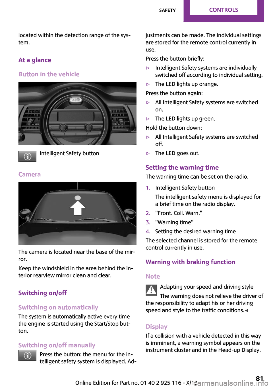
Intelligent Safety button
Camera
The camera is located near the base of the mir‐
ror.
Keep the windshield in the area behind the in‐
terior rearview mirror clean and clear.
Switching on/off
Switching on automatically
The system is automatically active every time
the engine is started using the Start/Stop but‐
ton.
Switching on/off manually Press the button: the menu for the in‐
telligent safety system is displayed. Ad‐
justments can be made. The individual settings
are stored for the remote control currently in
use.
Press the button briefly:▷Intelligent Safety systems are individually
switched off according to individual setting.▷The LED lights up orange.
Press the button again:
▷All Intelligent Safety systems are switched
on.▷The LED lights up green.
Hold the button down:
▷All Intelligent Safety systems are switched
off.▷The LED goes out.
Setting the warning time
The warning time can be set on the radio.
1.Intelligent Safety button
The intelligent safety menu is displayed for
a brief time on the radio display.2."Front. Coll. Warn."3."Warning time"4.Setting the desired warning time
The selected channel is stored for the remote
control currently in use.
Warning with braking function Note Adapting your speed and driving style
The warning does not relieve the driver of
the responsibility to adapt his or her driving
speed and style to the traffic conditions. ◀
Display If a collision with a vehicle detected in this way
is imminent, a warning symbol appears on the
instrument cluster and in the Head-up Display.
Seite 81SafetyControls81
Online Edition for Part no. 01 40 2 925 116 - X/13
Page 87 of 233
Pedestrian warning with
city braking function
The concept
The system can help to prevent accidents with
pedestrians.
The system issues a warning in the city driving
speed area if there is imminent danger of a col‐
lision with pedestrians and includes a braking
function.
The system is controlled via the camera in the
base of the interior mirror.
General information
The system issues a warning with brightness
staring at approx. 6 mph/10 km/h to approx.
35 mph/60 km/h regarding a possible risk of
collision with pedestrians and assists with a
brake intervention shortly before a collision.
It responds to persons that are within the de‐
tection range of the system.
Detection range
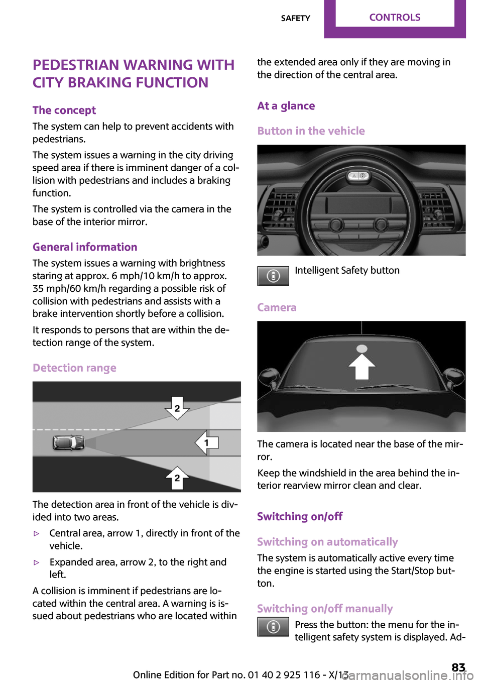
The detection area in front of the vehicle is div‐
ided into two areas.
▷Central area, arrow 1, directly in front of the
vehicle.▷Expanded area, arrow 2, to the right and
left.
A collision is imminent if pedestrians are lo‐
cated within the central area. A warning is is‐
sued about pedestrians who are located within
the extended area only if they are moving in
the direction of the central area.
At a glance
Button in the vehicle
Intelligent Safety button
Camera
The camera is located near the base of the mir‐
ror.
Keep the windshield in the area behind the in‐
terior rearview mirror clean and clear.
Switching on/off
Switching on automatically
The system is automatically active every time
the engine is started using the Start/Stop but‐
ton.
Switching on/off manually Press the button: the menu for the in‐
telligent safety system is displayed. Ad‐
Seite 83SafetyControls83
Online Edition for Part no. 01 40 2 925 116 - X/13
Page 88 of 233
justments can be made. The individual settings
are stored for the remote control currently in
use.
Press the button briefly:▷Intelligent Safety systems are individually
switched off according to individual setting.▷The LED lights up orange.
Press the button again:
▷All Intelligent Safety systems are switched
on.▷The LED lights up green.
Hold the button down:
▷All Intelligent Safety systems are switched
off.▷The LED goes out.
Warning with braking function
Note Adapting your speed and driving style
The warning does not relieve the driver of
the responsibility to adapt his or her driving
speed and style to the traffic conditions. ◀
Display
If a collision with a person detected in this way
is imminent, a warning symbol appears on the
instrument cluster and in the Head-up Display.
The red symbol is displayed and a signalsounds.
Intervene immediately by braking or
making an evasive maneuver.
Braking intervention
The warning prompts the driver himself to in‐
tervene. During a warning, the maximum brak‐ ing force is used. A prerequisite for the brake
booster is a sufficiently fast and sufficiently
strong actuation of the brake pedal. In addi‐
tion, if there is a risk of collision, the system can
assist with a slight braking intervention. The in‐
tervention can bring a vehicle traveling at slow
speed to a complete stop.
Manual transmission: During a braking inter‐
vention up until reaching a complete stop, the
engine may be shut down.
The braking intervention is executed only if DSC
Dynamic Stability Control is switched on and
Dynamic Traction Control DTC is activated.
The braking intervention can be interrupted by
pressing on the accelerator pedal or by actively
moving the steering wheel.
Tow-starting and towing
When tow-starting and towing the vehi‐
cle, switch off the Intelligent Safety systems;
otherwise, improper behavior of the braking
function of individual systems could result in an
accident. ◀
System limits Be alert
Due to system limitations, warnings may
be not be issued at all, or may be issued late or
improperly. Therefore, always be alert and
ready to intervene; otherwise, there is the dan‐
ger of an accident occurring. ◀
Detection range The detection capability of the camera is lim‐
ited.
This may result in the warning not being issued
or being issued late.
For example, the following situations may not
be detected:▷Partially covered pedestrians.▷Pedestrians that are not detected as such
because of the viewing angle or contour.▷Pedestrians outside of the detection range.▷Pedestrians having a body size less than
32 in/80 cm.Seite 84ControlsSafety84
Online Edition for Part no. 01 40 2 925 116 - X/13
Page 90 of 233
Driving stability control systemsVehicle equipment
All standard, country-specific and optional
equipment that is offered in the model series is
described in this chapter. Therefore, equipment
is also described that is not available in a vehi‐
cle, e. g., because of the selected optional
equipment or country variant. This also applies
for safety-related functions and systems.
Antilock Brake System
ABS
ABS prevents locking of the wheels during
braking.
The vehicle remains steerable even during full
brake applications, thus increasing active
safety.
ABS is operational every time you start the en‐
gine.
Brake assistant When you apply the brakes rapidly, this systemautomatically produces the maximum braking
force boost. This then reduces braking distance
to a minimum during full braking. This system
utilizes all of the benefits provided by ABS.
Do not reduce the pressure on the brake pedal
for the duration of the full braking.
DSC Dynamic Stability
Control
The concept
DSC prevents traction loss in the driving wheels
when driving away and accelerating.DSC also recognizes unstable vehicle condi‐
tions, such as fishtailing or nose-diving. Subject
to physical limits, DSC helps to keep the vehicle
on a steady course by reducing engine speed
and by applying brakes to the individual
wheels.
Adjust your driving style to the situation
An appropriate driving style is always the
responsibility of the driver.
The laws of physics cannot be repealed, even
with DSC.
Therefore, do not reduce the additional safety
margin by driving in a risky manner. ◀
Indicator/warning lamps The indicator lamp flashes: DSC controls
the drive forces and brake forces.
The indicator lamp lights up: DSC has
failed.
Deactivating DSC: DSC OFF
When DSC is deactivated, driving stability is re‐
duced during acceleration and when driving in
bends.
To increase vehicle stability, activate DSC again
as soon as possible.
Deactivating DSC Press and hold the button, but not lon‐
ger than approx. 10 seconds, until the
indicator lamp for DSC OFF lights up in the in‐
strument cluster and DSC OFF is displayed.
The DSC system is switched off.
Activating DSC Press the button.Seite 86ControlsDriving stability control systems86
Online Edition for Part no. 01 40 2 925 116 - X/13
Page 94 of 233
Driving comfortVehicle equipment
All standard, country-specific and optional
equipment that is offered in the model series is
described in this chapter. Therefore, equipment
is also described that is not available in a vehi‐
cle, e. g., because of the selected optional
equipment or country variant. This also applies
for safety-related functions and systems.
Camera-based cruise con‐
trol, ACC
The concept
This system can be used to select a desired
speed that the vehicle will maintain automati‐
cally on clear roads.
To the extent possible, the system automati‐
cally adjusts the speed to a slower vehicle
ahead of you.
A camera on the interior rear view mirror is
used to detect vehicles driving ahead.
The distance that the vehicle maintains to the
vehicle ahead of you can be varied.
For safety reasons, it depends on the speed.
To maintain a certain distance, the system au‐
tomatically decelerates, applies the brakes
lightly, or accelerates again if the vehicle ahead
begins moving faster.
As soon as the road is clear, it accelerates to the
desired speed.
The speed is also maintained on downhill gradi‐
ents, but may not be maintained on uphill
slopes if engine power is insufficient.
General information
Depending on the set drive mode, refer to
page 88, the characteristics of the cruise con‐
trol can change in certain areas.Hints
Personal responsibility
Even an active system does not release
the driver from personal responsibility for the
driving process, especially for lane tracking, adaptation of speed, distance and driving style
to the traffic conditions.
Because of technical system limits, the system
cannot independently react appropriately in all
traffic situations.
Monitor the driving process, the surrounding
area and what is occurring in traffic continu‐
ously and attentively and actively intervene as
required, e.g., by braking, steering or making
an evasive maneuver. ◀
Unfavorable weather conditions
Unfavorable weather conditions, e.g.,
rain, snowfall or slush, may result in worsened
detection of vehicles as well as short-term in‐
terruptions with already detected vehicles.
Drive attentively, and react to the current traffic
events. Intervene actively when necessary, e.g.,
by braking, steering or making an evasive ma‐
neuver, otherwise, there is danger of an acci‐
dent. ◀
At a glance
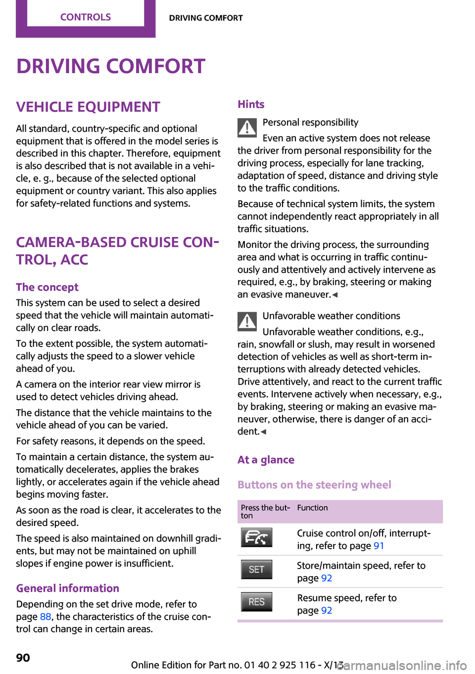
Buttons on the steering wheelPress the but‐
tonFunctionCruise control on/off, interrupt‐
ing, refer to page 91Store/maintain speed, refer to
page 92Resume speed, refer to
page 92Seite 90ControlsDriving comfort90
Online Edition for Part no. 01 40 2 925 116 - X/13
Page 96 of 233
Maintaining/storing the speedPress the button.
Or:
or Press button in the interrupted state.
When the system is switched on, the current
speed is maintained and stored as the desired
speed.
The speed is displayed on the symbol.
When cruise control is maintained or
stored, DSC Dynamic Stability Control is
switched on, if necessary.
Changing, maintaining, and storing the
speed
or button: by pressing one of the but‐
tons while the system is interrupted, the cur‐
rent speed can be maintained and stored. DSC
Dynamic Stability Control is switched on, if nec‐
essary.
Adapting the desired speed
Adapt the desired speed to the road con‐
ditions and be ready to brake at all times; oth‐
erwise, there is the danger of an accident oc‐
curring. ◀
Speed differences
Large differences in speed relative to
other vehicles cannot be compensated by the
system for example in the following situations:
▷When catching up rapidly with slow-moving
vehicles.▷When another vehicle suddenly swerves
into the wrong lane.▷When stationary objects are approached at
speed. ◀
or button: press until the desired speed
is set.
If active, the displayed speed is stored and the
vehicle reaches the stored speed if the road is
clear.
▷ or button: each time it is pressed to
the point of resistance, the desired speed
increases or decreases by approx.
1 mph/1 km/h.▷ or button: each time it is pressed
past the point of resistance, the desired
speed increases or decreases by a maxi‐
mum of 5 mph/10 km/h.
or button: hold down to repeat the cor‐
responding action.
Distance Selecting a distance
Adjust the distance according to the traf‐
fic and weather conditions; otherwise, there is
the danger of an accident occurring. Maintain
the prescribed safety distance. ◀
Reduce distance Press the button repeatedly until the
desired distance is set.
The set distance increment is briefly dis‐
played in the left part of the instrument
cluster.
Increase distance Press the button repeatedly until the
desired distance is set.
The set distance increment is briefly dis‐
played in the left part of the instrument
cluster.
Calling up the desired speed and
distance
While driving Press the button with the system inter‐
rupted. The regulation of the desired
speed and distance is continued with the
Seite 92ControlsDriving comfort92
Online Edition for Part no. 01 40 2 925 116 - X/13
Page 97 of 233
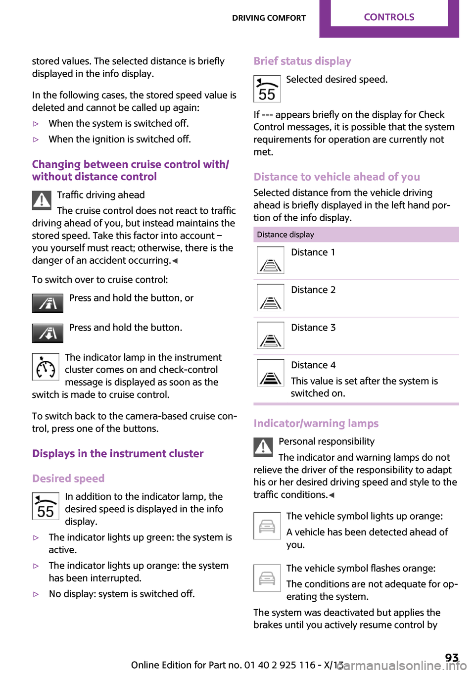
stored values. The selected distance is briefly
displayed in the info display.
In the following cases, the stored speed value is
deleted and cannot be called up again:▷When the system is switched off.▷When the ignition is switched off.
Changing between cruise control with/
without distance control
Traffic driving ahead
The cruise control does not react to traffic
driving ahead of you, but instead maintains the
stored speed. Take this factor into account – you yourself must react; otherwise, there is the
danger of an accident occurring. ◀
To switch over to cruise control: Press and hold the button, or
Press and hold the button.
The indicator lamp in the instrument
cluster comes on and check-control
message is displayed as soon as the
switch is made to cruise control.
To switch back to the camera-based cruise con‐
trol, press one of the buttons.
Displays in the instrument cluster
Desired speed In addition to the indicator lamp, the
desired speed is displayed in the info
display.
▷The indicator lights up green: the system is
active.▷The indicator lights up orange: the system
has been interrupted.▷No display: system is switched off.Brief status display
Selected desired speed.
If --- appears briefly on the display for Check
Control messages, it is possible that the system
requirements for operation are currently not met.
Distance to vehicle ahead of you
Selected distance from the vehicle driving
ahead is briefly displayed in the left hand por‐
tion of the info display.Distance displayDistance 1Distance 2Distance 3Distance 4
This value is set after the system is
switched on.
Indicator/warning lamps
Personal responsibility
The indicator and warning lamps do not
relieve the driver of the responsibility to adapt
his or her desired driving speed and style to the
traffic conditions. ◀
The vehicle symbol lights up orange:
A vehicle has been detected ahead of
you.
The vehicle symbol flashes orange:
The conditions are not adequate for op‐
erating the system.
The system was deactivated but applies the
brakes until you actively resume control by
Seite 93Driving comfortControls93
Online Edition for Part no. 01 40 2 925 116 - X/13
Page 104 of 233
▷When using high-pressure washers, do not
spray the sensors for long periods and
maintain a distance of at least 12 in/30 cm.
Parking assistant
The concept
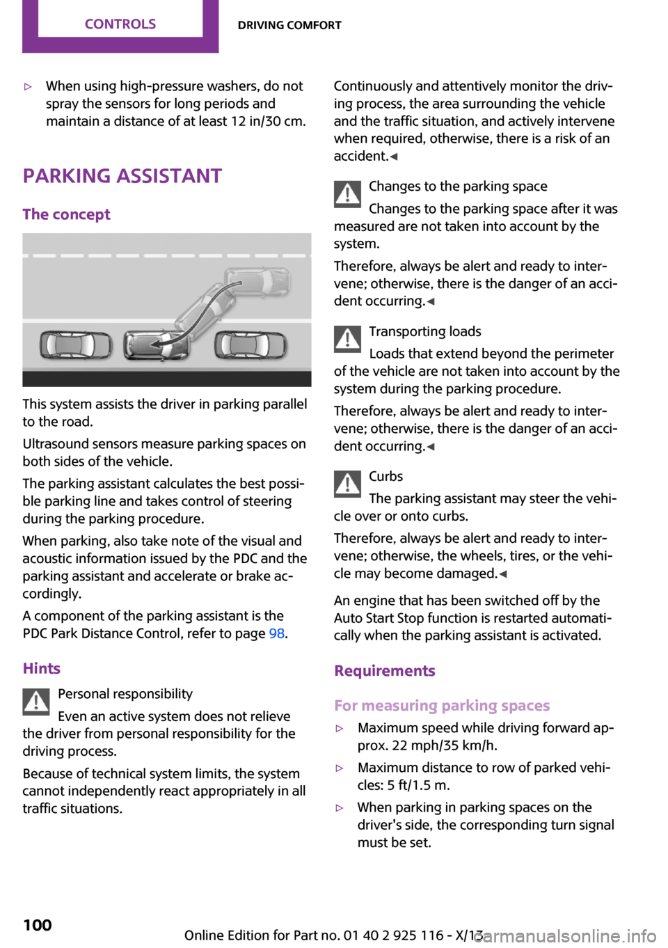
This system assists the driver in parking parallel
to the road.
Ultrasound sensors measure parking spaces on
both sides of the vehicle.
The parking assistant calculates the best possi‐
ble parking line and takes control of steering
during the parking procedure.
When parking, also take note of the visual and
acoustic information issued by the PDC and the
parking assistant and accelerate or brake ac‐
cordingly.
A component of the parking assistant is the
PDC Park Distance Control, refer to page 98.
Hints Personal responsibility
Even an active system does not relieve
the driver from personal responsibility for the
driving process.
Because of technical system limits, the system
cannot independently react appropriately in all
traffic situations.
Continuously and attentively monitor the driv‐
ing process, the area surrounding the vehicle
and the traffic situation, and actively intervene
when required, otherwise, there is a risk of an
accident. ◀
Changes to the parking space
Changes to the parking space after it was
measured are not taken into account by the
system.
Therefore, always be alert and ready to inter‐
vene; otherwise, there is the danger of an acci‐
dent occurring. ◀
Transporting loads
Loads that extend beyond the perimeter
of the vehicle are not taken into account by the
system during the parking procedure.
Therefore, always be alert and ready to inter‐
vene; otherwise, there is the danger of an acci‐
dent occurring. ◀
Curbs
The parking assistant may steer the vehi‐
cle over or onto curbs.
Therefore, always be alert and ready to inter‐
vene; otherwise, the wheels, tires, or the vehi‐
cle may become damaged. ◀
An engine that has been switched off by the
Auto Start Stop function is restarted automati‐
cally when the parking assistant is activated.
Requirements
For measuring parking spaces▷Maximum speed while driving forward ap‐
prox. 22 mph/35 km/h.▷Maximum distance to row of parked vehi‐
cles: 5 ft/1.5 m.▷When parking in parking spaces on the
driver's side, the corresponding turn signal
must be set.Seite 100ControlsDriving comfort100
Online Edition for Part no. 01 40 2 925 116 - X/13