ECU MINI Clubman 2010 Owner's Manual (Mini Connected)
[x] Cancel search | Manufacturer: MINI, Model Year: 2010, Model line: Clubman, Model: MINI Clubman 2010Pages: 218, PDF Size: 3.97 MB
Page 21 of 218
MOBILITYAT A GLANCE CONTROLS DRIVING TIPS ENTERTAINMENT
19
NAVIGATION REFERENCE
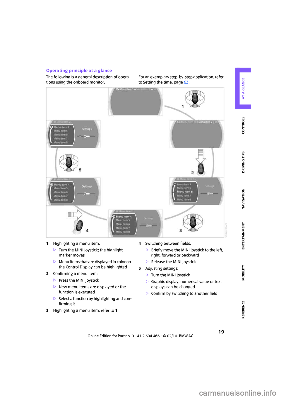
Operating principle at a glance
The following is a general description of opera-
tions using the onboard monitor.For an exemplary step-by-step application, refer
to Setting the time, page63.
1Highlighting a menu item:
>Turn the MINI joystick; the highlight
marker moves
>Menu items that are displayed in color on
the Control Display can be highlighted
2Confirming a menu item:
>Press the MINI joystick
>New menu items are displayed or the
function is executed
>Select a function by highlighting and con-
firming it
3Highlighting a menu item: refer to14Switching between fields:
>Briefly move the MINI joystick to the left,
right, forward or backward
>Release the MINI joystick
5Adjusting settings:
>Turn the MINI joystick
>Graphic display, numerical value or text
displays can be changed
>Confirm by switching to another field
Page 45 of 218
MOBILITYAT A GLANCE CONTROLS DRIVING TIPS ENTERTAINMENT
43
NAVIGATION REFERENCE
Transporting children safely
The right place for
children
Do not leave children unattended in the
vehicle; otherwise, they could endanger
themselves and/or other persons by opening the
doors, for example.<
Children should always sit in the rear
Accident research has shown that the safest
place for children is on the rear seat.
Only transport children under the age of
13 or smaller than 5 ft/150 cm in the rear
in a child restraint system suitable for their age,
weight and size. Otherwise, there is an
increased risk of injury in the event of an acci-
dent.<
Children 13 years of age or older must be buck-
led in with a safety belt as soon as there no
longer is any child restraint system that is appro-
priate for their age, size and weight.
Only install child seats in the rear when the
rear seat backrest is folded all the way
back and engaged. Otherwise, there is an
increased risk of injury in the event of an acci-
dent.<
Exception for front passenger seat
Front passenger airbags
Should it be necessary to use a child
restraint system on the front passenger
seat, the front and side airbags must be deacti-
vated. Otherwise, there is an increased risk of
injury to the child if the airbags deploy, even if
the child is seated in a child restraint system.<
For more information on automatic deactivation
of the front passenger airbags, refer to page79.
Child restraint systems,
installation
Observe the child restraint system manu-
facturer's instructions when selecting,
installing and using child restraint systems. Oth-
erwise, the protective effect may be dimin-
ished.<
On the front passenger seat
After installing a child restraint system on
the front passenger seat, make sure that
the front and side airbags for the front passen-
ger are deactivated; otherwise, there is an
increased risk of injury if the airbags deploy.<
Seat position
Before installing a child restraint system, move
the front passenger seat as far back and up
* as
possible to obtain the best possible position for
the belt. Do not change the seat position after
this.
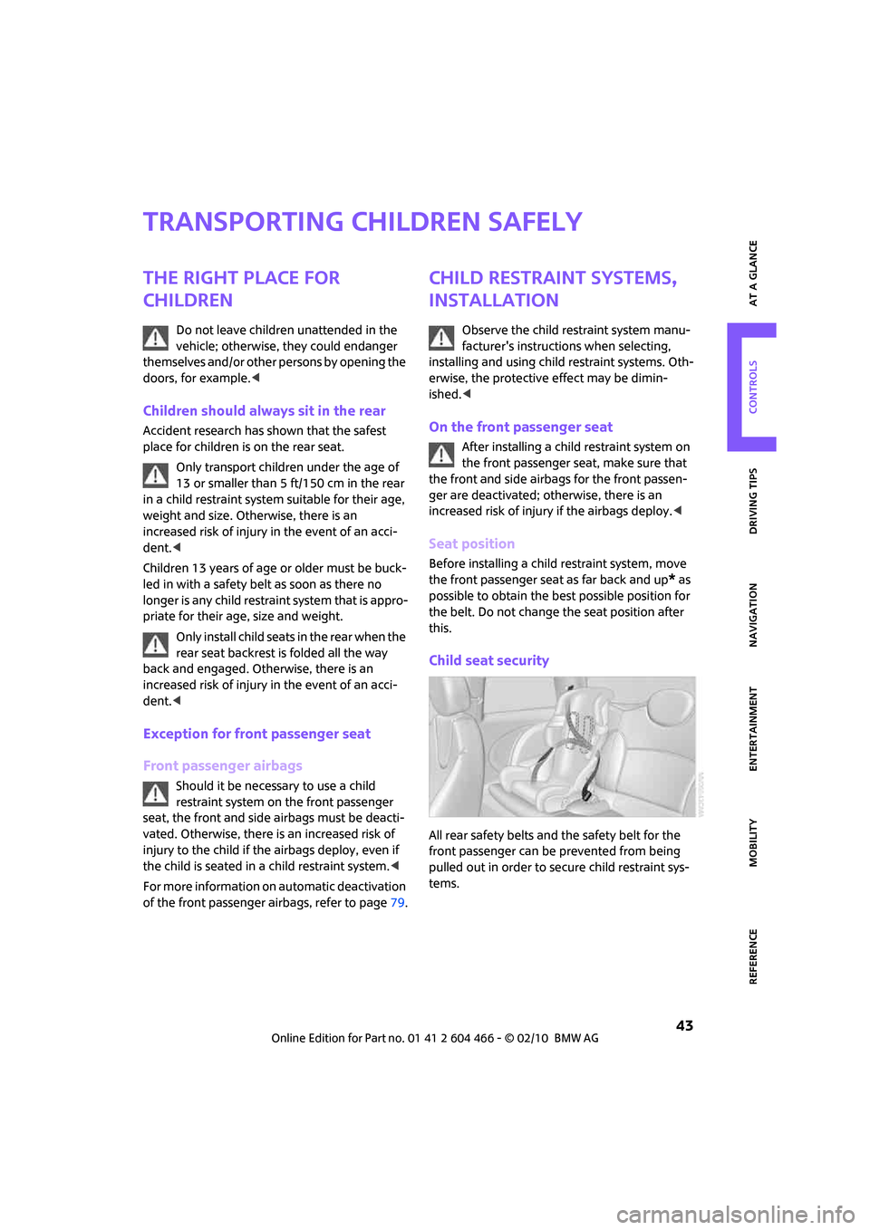
Child seat security
All rear safety belts and the safety belt for the
front passenger can be prevented from being
pulled out in order to secure child restraint sys-
tems.
Page 46 of 218
Transporting children safely
44
To lock the safety belt
1.Secure the child restraint system with the
belt.
2.Pull the belt strap all the way out.
3.Allow the belt strap to retract and pull it taut
against the child restraint system.
The safety belt is locked.
To unlock the safety belt
1.Open the belt buckle.
2.Remove the child restraint system.
3.Allow the safety belt strap to retract all the
way.
LATCH child-restraint
fixing system
LATCH: lower Anchors and Tethers for CHildren.
To install and use the LATCH child restraint
system, follow the operating and safety
instructions provided by the manufacturer of the
system; otherwise, the protective function of the
seat may be compromised.<
Anchor points for LATCH anchors
Before installing the child seat, pull the belt out
of the area for the child-restraint fixing system.
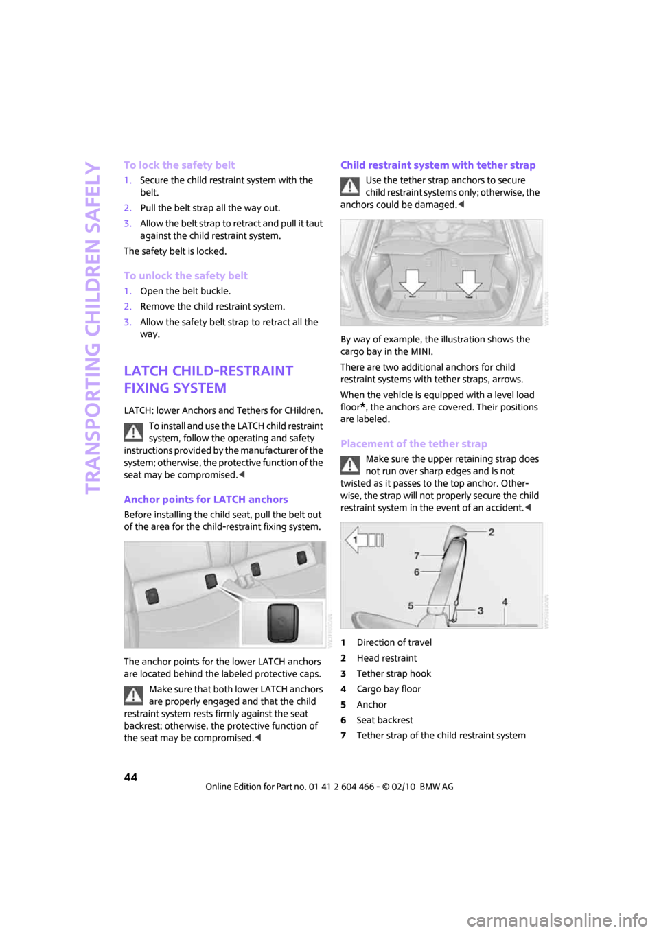
The anchor points for the lower LATCH anchors
are located behind the labeled protective caps.
Make sure that both lower LATCH anchors
are properly engaged and that the child
restraint system rests firmly against the seat
backrest; otherwise, the protective function of
the seat may be compromised.<
Child restraint system with tether strap
Use the tether strap anchors to secure
child restraint systems only; otherwise, the
anchors could be damaged.<
By way of example, the illustration shows the
cargo bay in the MINI.
There are two additional anchors for child
restraint systems with tether straps, arrows.
When the vehicle is equipped with a level load
floor
*, the anchors are covered. Their positions
are labeled.
Placement of the tether strap
Make sure the upper retaining strap does
not run over sharp edges and is not
twisted as it passes to the top anchor. Other-
wise, the strap will not properly secure the child
restraint system in the event of an accident.<
1Direction of travel
2Head restraint
3Tether strap hook
4Cargo bay floor
5Anchor
6Seat backrest
7Tether strap of the child restraint system
Page 51 of 218
MOBILITYAT A GLANCE CONTROLS DRIVING TIPS ENTERTAINMENT
49
NAVIGATION REFERENCE
To prevent the vehicle from creeping
after you select a driving position,
depress the brake until you are ready to
start.<
A lock prevents accidental shifting into selector
lever positions R and P.
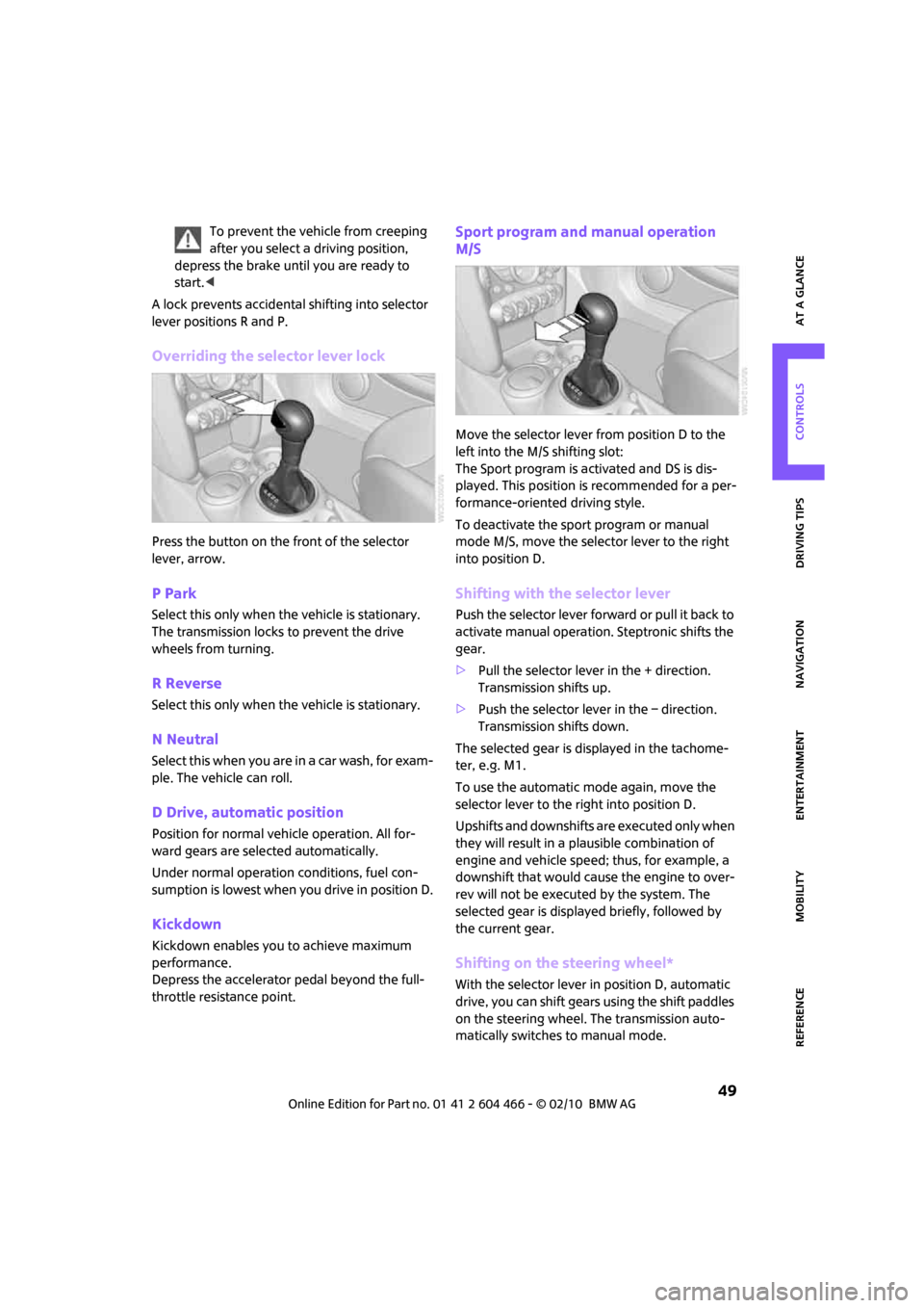
Overriding the selector lever lock
Press the button on the front of the selector
lever, arrow.
P Park
Select this only when the vehicle is stationary.
The transmission locks to prevent the drive
wheels from turning.
R Reverse
Select this only when the vehicle is stationary.
N Neutral
Select this when you are in a car wash, for exam-
ple. The vehicle can roll.
D Drive, automatic position
Position for normal vehicle operation. All for-
ward gears are selected automatically.
Under normal operation conditions, fuel con-
sumption is lowest when you drive in position D.
Kickdown
Kickdown enables you to achieve maximum
performance.
Depress the accelerator pedal beyond the full-
throttle resistance point.
Sport program and manual operation
M/S
Move the selector lever from position D to the
left into the M/S shifting slot:
The Sport program is activated and DS is dis-
played. This position is recommended for a per-
formance-oriented driving style.
To deactivate the sport program or manual
mode M/S, move the selector lever to the right
into position D.
Shifting with the selector lever
Push the selector lever forward or pull it back to
activate manual operation. Steptronic shifts the
gear.
>Pull the selector lever in the + direction.
Transmission shifts up.
>Push the selector lever in the – direction.
Transmission shifts down.
The selected gear is displayed in the tachome-
ter, e.g. M1.
To use the automatic mode again, move the
selector lever to the right into position D.
Upshifts and downshifts are executed only when
they will result in a plausible combination of
engine and vehicle speed; thus, for example, a
downshift that would cause the engine to over-
rev will not be executed by the system. The
selected gear is displayed briefly, followed by
the current gear.
Shifting on the steering wheel*
With the selector lever in position D, automatic
drive, you can shift gears using the shift paddles
on the steering wheel. The transmission auto-
matically switches to manual mode.
Page 74 of 218
Technology for driving comfort and safety
72
DSC also encompasses the following functions:
>Antilock Brake System ABS
>Electronic brake-force distribution EBV
>Brake Assist
>Cornering Brake Control CBC
>Hill Assist
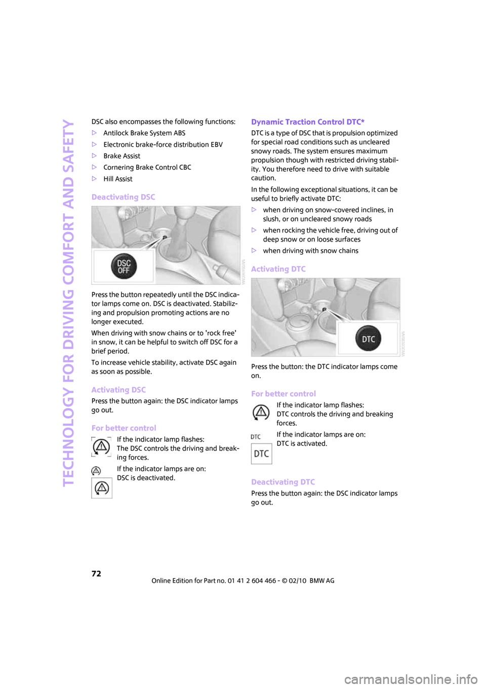
Deactivating DSC
Press the button repeatedly until the DSC indica-
tor lamps come on. DSC is deactivated. Stabiliz-
ing and propulsion promoting actions are no
longer executed.
When driving with snow chains or to 'rock free'
in snow, it can be helpful to switch off DSC for a
brief period.
To increase vehicle stability, activate DSC again
as soon as possible.
Activating DSC
Press the button again: the DSC indicator lamps
go out.
For better control
If the indicator lamp flashes:
The DSC controls the driving and break-
ing forces.
If the indicator lamps are on:
DSC is deactivated.
Dynamic Traction Control DTC*
DTC is a type of DSC that is propulsion optimized
for special road conditions such as uncleared
snowy roads. The system ensures maximum
propulsion though with restricted driving stabil-
ity. You therefore need to drive with suitable
caution.
In the following exceptional situations, it can be
useful to briefly activate DTC:
>when driving on snow-covered inclines, in
slush, or on uncleared snowy roads
>when rocking the vehicle free, driving out of
deep snow or on loose surfaces
>when driving with snow chains
Activating DTC
Press the button: the DTC indicator lamps come
on.
For better control
If the indicator lamp flashes:
DTC controls the driving and breaking
forces.
If the indicator lamps are on:
DTC is activated.
Deactivating DTC
Press the button again: the DSC indicator lamps
go out.
Page 81 of 218
MOBILITYAT A GLANCE CONTROLS DRIVING TIPS ENTERTAINMENT
79
NAVIGATION REFERENCE
Airbags
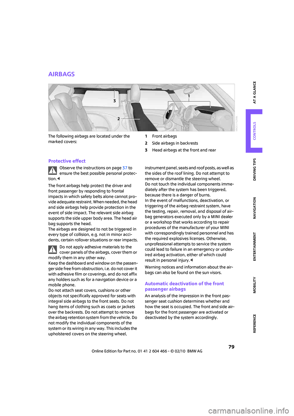
The following airbags are located under the
marked covers:1Front airbags
2Side airbags in backrests
3Head airbags at the front and rear
Protective effect
Observe the instructions on page37 to
ensure the best possible personal protec-
tion.<
The front airbags help protect the driver and
front passenger by responding to frontal
impacts in which safety belts alone cannot pro-
vide adequate restraint. When needed, the head
and side airbags help provide protection in the
event of side impact. The relevant side airbag
supports the side upper body area. The head air
bag supports the head.
The airbags are designed to not be triggered in
every type of collision, e.g. not in minor acci-
dents, certain rollover situations or rear impacts.
Do not apply adhesive materials to the
cover panels of the airbags, cover them or
modify them in any other way.
Keep the dashboard and window on the passen-
ger side free from obstruction, i.e. do not cover it
with adhesive film or coverings, and do not affix
any holders such as for a navigation device or a
mobile phone.
Do not attach seat covers, cushions or other
objects not specifically approved for seats with
integral side airbags to the front seats. Do not
hang items of clothing such as coats or jackets
over the backrests. Do not attempt to remove
the airbag retention system from the vehicle. Do
not modify the individual components of the
system or its wiring in any way. This includes the
upholstered covers on the steering wheel, instrument panel, seats and roof posts, as well as
the sides of the roof lining. Do not attempt to
remove or dismantle the steering wheel.
Do not touch the individual components imme-
diately after the system has been triggered,
because there is a danger of burns.
In the event of malfunctions, deactivation, or
triggering of the airbag restraint system, have
the testing, repair, removal, and disposal of air-
bag generators executed only by a MINI dealer
or a workshop that works according to repair
procedures of the manufacturer of your MINI
with correspondingly trained personnel and has
the required explosives licenses. Otherwise,
unprofessional attempts to service the system
could lead to failure in an emergency or undes-
ired airbag activation, either of which could
result in personal injury.<
Warning notices and information about the air-
bags can also be found on the sun visors.
Automatic deactivation of the front
passenger airbags
An analysis of the impression in the front pas-
senger seat cushion determines whether and
how the seat is occupied. The front and side air-
bags for the front passenger are activated or
deactivated by the system accordingly.
Page 90 of 218
Practical interior accessories
88
Practical interior accessories
Integrated universal
remote control*
The concept
The integrated universal remote control can
replace as many as three hand-held transmitters
for various remote-controlled devices, such as
garage and gate openers and lighting systems.
The integrated universal remote control regis-
ters and stores signals from the original hand-
held transmitters.
The signal of an original hand-held transmitter
can be programmed on one of the three mem-
ory buttons1. The system in question can then
be operated by means of the programmed
memory button1. The LED2 flashes to confirm
transmission of the signal.
If you decide to sell your vehicle one day, in the
interest of your own security, remember to clear
the stored programs before the vehicle leaves
your possession, page89.
To prevent possible damage or injury,
before programming or using the inte-
grated universal remote control, always inspect
the immediate area to make certain that no
people, animals or objects are within the pivot-
ing or travel range of the device being operated.
Comply also with the safety instructions supplied
with the original hand-held transmitter.<
Checking compatibility
If this symbol appears on the package
or in the instructions supplied with the
original hand-held transmitter, you can
assume that the radio remote control device is
compatible with the integrated universal remote
control.
For additional information, please contact your
MINI dealer or call: 1-800-355-3515.
You can also obtain information on the Internet
at:
www.MINI.com orwww.homelink.com
HomeLink is a registered trademark of Johnson
Controls, Inc.
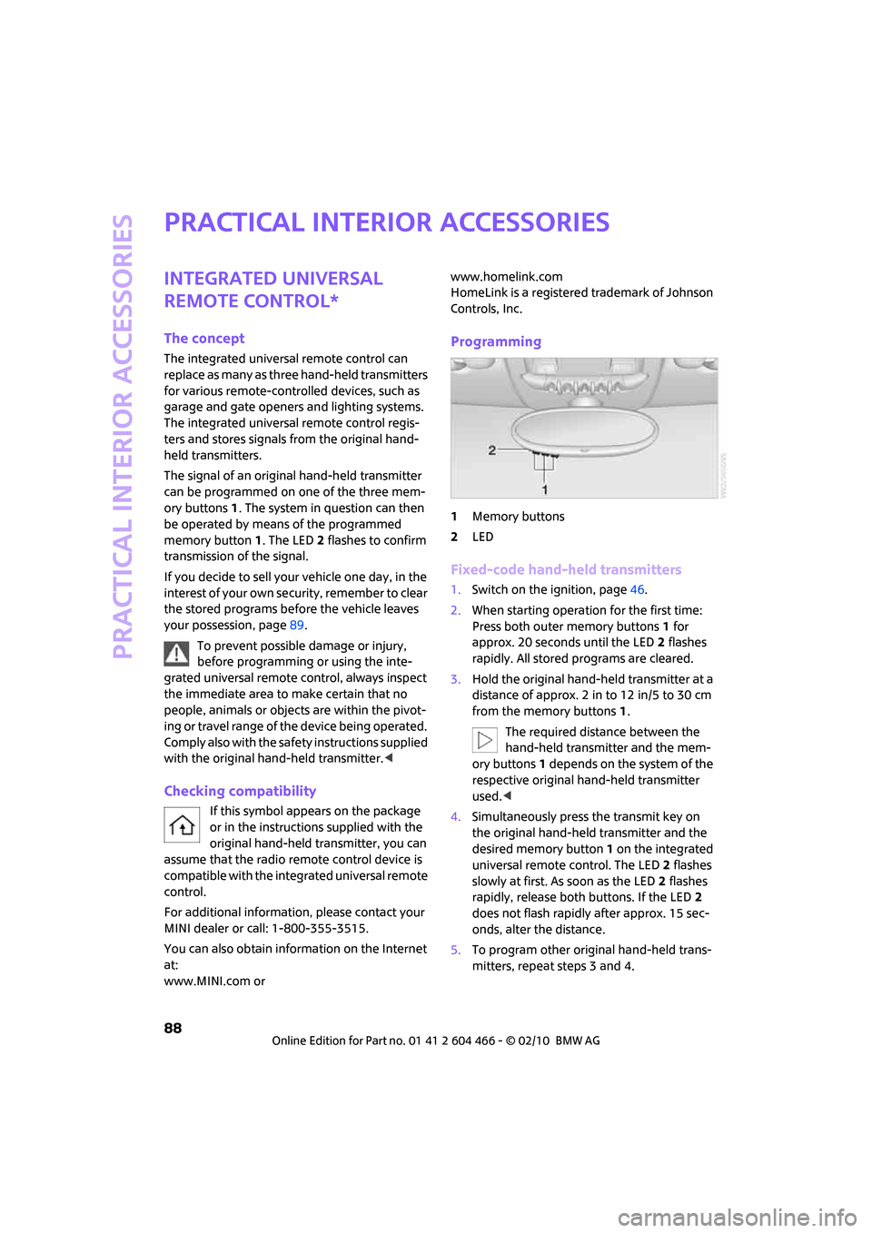
Programming
1Memory buttons
2LED
Fixed-code hand-held transmitters
1.Switch on the ignition, page46.
2.When starting operation for the first time:
Press both outer memory buttons1 for
approx. 20 seconds until the LED2 flashes
rapidly. All stored programs are cleared.
3.Hold the original hand-held transmitter at a
distance of approx. 2 in to 12 in/5 to 30 cm
from the memory buttons1.
The required distance between the
hand-held transmitter and the mem-
ory buttons1 depends on the system of the
respective original hand-held transmitter
used.<
4.Simultaneously press the transmit key on
the original hand-held transmitter and the
desired memory button 1 on the integrated
universal remote control. The LED 2 flashes
slowly at first. As soon as the LED2 flashes
rapidly, release both buttons. If the LED2
does not flash rapidly after approx. 15 sec-
onds, alter the distance.
5.To program other original hand-held trans-
mitters, repeat steps 3 and 4.
Page 102 of 218
Things to remember when driving
100
2.Determine the combined weight of the
driver and passengers that will be riding in
your vehicle.
3.Subtract the combined weight of the driver
and passengers from XXX kilograms or YYY
pounds.
4.The resulting figure equals the available
amount of cargo and luggage load capacity.
For example, if the XXX amount equals
1,400 lbs and there will be four 150 lbs pas-
sengers in your vehicle, the amount of avail-
able cargo and luggage load capacity is
650 lbs:
1,400 lbs minus 750 lbs = 650 lbs.
5.Determine the combined weight of luggage
and cargo being loaded on the vehicle. That
weight may not safely exceed the available
cargo and luggage load capacity calculated
in step 4.
6.I f y o u r v e h icl e w i ll be t o w i n g a t r a il e r , pa r t o f
the load from your trailer will be transferred
to your vehicle. Consult the manual for
transporting a trailer to determine how this
may reduce the available cargo and luggage
load capacity of your vehicle.
Load
The permissible load is the sum of the occu-
pants' weights and the weight of the cargo. The
greater the weight of the occupants, the less
cargo/luggage can be transported.
Stowing cargo
>Position heavy objects as low and as far for-
ward as possible, ideally directly behind the
rear seat backrests.
>Cover sharp edges and corners.>For very heavy cargo when the rear seat is
not occupied, secure each safety belt in the
respective opposite buckle.
>Do not stack higher than the top edge of the
backrests.
>Use the partition net, refer to page99.
Ensure that no objects can penetrate
through the net.
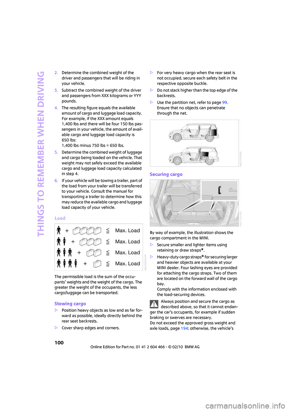
Securing cargo
By way of example, the illustration shows the
cargo compartment in the MINI.
>Secure smaller and lighter items using
retaining or draw straps
*.
>Heavy-duty cargo straps
* for securing larger
and heavier objects are available at your
MINI dealer. Four lashing eyes are provided
for attaching the cargo straps. Two of them
are located on the forward wall of the cargo
bay.
Comply with the information enclosed with
the load-securing devices.
Always position and secure the cargo as
described above, so that it cannot endan-
ger the car's occupants, for example if sudden
braking or swerves are necessary.
Do not exceed the approved gross weight and
axle loads, page194; otherwise, the vehicle's
Page 103 of 218
MOBILITYAT A GLANCE CONTROLS DRIVING TIPS ENTERTAINMENT
101
NAVIGATION REFERENCE
operating safety is no longer assured and the
vehicle will not be in compliance with the certifi-
cation regulations.
Heavy or hard objects should not be carried
loose inside the car, since they could be thrown
around, for example as a result of heavy braking,
sudden swerves, etc., and endanger the occu-
pants. Do not secure cargo using the fastening
points for the tether strap, page44; they may
become damaged.<
Roof-mounted luggage
rack*
A special rack system is available as an option for
your MINI. Your MINI dealer will be glad to
advise you. Comply with the installation instruc-
tions supplied with the rack system.
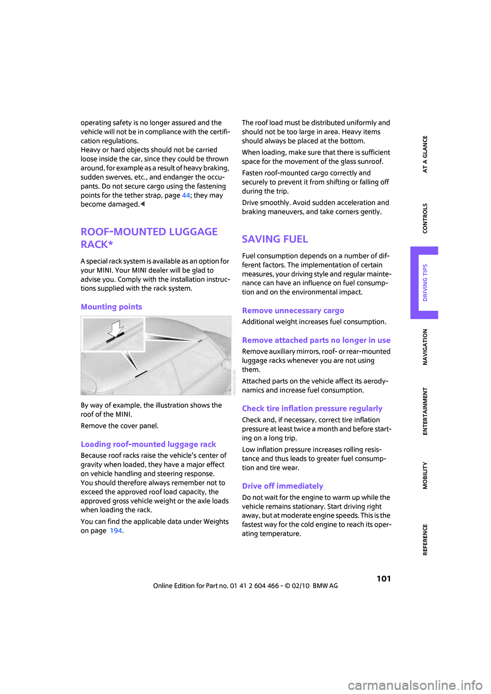
Mounting points
By way of example, the illustration shows the
roof of the MINI.
Remove the cover panel.
Loading roof-mounted luggage rack
Because roof racks raise the vehicle's center of
gravity when loaded, they have a major effect
on vehicle handling and steering response.
You should therefore always remember not to
exceed the approved roof load capacity, the
approved gross vehicle weight or the axle loads
when loading the rack.
You can find the applicable data under Weights
on page 194.The roof load must be distributed uniformly and
should not be too large in area. Heavy items
should always be placed at the bottom.
When loading, make sure that there is sufficient
space for the movement of the glass sunroof.
Fasten roof-mounted cargo correctly and
securely to prevent it from shifting or falling off
during the trip.
Drive smoothly. Avoid sudden acceleration and
braking maneuvers, and take corners gently.
Saving fuel
Fuel consumption depends on a number of dif-
ferent factors. The implementation of certain
measures, your driving style and regular mainte-
nance can have an influence on fuel consump-
tion and on the environmental impact.
Remove unnecessary cargo
Additional weight increases fuel consumption.
Remove attached parts no longer in use
Remove auxiliary mirrors, roof- or rear-mounted
luggage racks whenever you are not using
them.
Attached parts on the vehicle affect its aerody-
namics and increase fuel consumption.
Check tire inflation pressure regularly
Check and, if necessary, correct tire inflation
pressure at least twice a month and before start-
ing on a long trip.
Low inflation pressure increases rolling resis-
tance and thus leads to greater fuel consump-
tion and tire wear.
Drive off immediately
Do not wait for the engine to warm up while the
vehicle remains stationary. Start driving right
away, but at moderate engine speeds. This is the
fastest way for the cold engine to reach its oper-
ating temperature.
Page 169 of 218

MOBILITYAT A GLANCE CONTROLS DRIVING TIPS ENTERTAINMENT
167
NAVIGATION REFERENCE
Under the hood
Do not work on the car unless you possess
the necessary technical knowledge. If you
are not familiar with the regulations to be
observed, have the necessary work on your
vehicle carried out only by a MINI dealer or a
workshop that has specially trained personnel
working in accordance with the specifications of
the MINI manufacturer. If this work is not carried
out properly, there is a danger of subsequent
damage and related safety hazards.<
Hood
Releasing
Pull the lever.
Do not clean the windshield and head-
lamps if the hood is unlocked as this may
damage the headlamp washer system
*.<
Opening
To avoid damage, make sure that the
wiper arms are against the windshield
before you open the hood.<
Press the release handle and open the hood.
Closing
Close the hood from a height of approx. 16 in/
40 cm with momentum. It must be clearly heard
to engage.
If you notice any signs while driving your
vehicle that the hood is not completely
closed, stop at once and close it securely.
Make sure that the closing path of the hood is
clear; otherwise, injuries may result.<