tow MINI Clubman 2010 User Guide
[x] Cancel search | Manufacturer: MINI, Model Year: 2010, Model line: Clubman, Model: MINI Clubman 2010Pages: 160, PDF Size: 2.58 MB
Page 104 of 160

Wheels and tires
102
RSC - run-flat tires*
You will recognize run-flat tires by a circular
symbol containing the letters RSC on the side of
the tire, page103.
M+S
Winter and all-season tires.
These have better winter properties than sum-
mer tires.
XL
Designation for specially reinforced tires.
Tire condition
Inspect your tires regularly for tread wear, signs
of damage and for foreign objects lodged in the
tread. Check the tread depth.
Tread depth
The tread depth should not drop below 1/8 in/
3 mm, although, for example, European legisla-
tion only specifies a minimum tread depth of
1/16 in/1.6 mm. At tread depths below 1/8 in/
3 mm there is an increased risk of high-speed
hydroplaning, even when only small amounts of
water are present on the road surface.
Winter tires
When winter tires wear down past a tread depth
of 1/6 in/4 mm, they become perceptibly less
suitable for winter conditions. In the interest of
safety, new tires should be installed.
Minimum tread depth
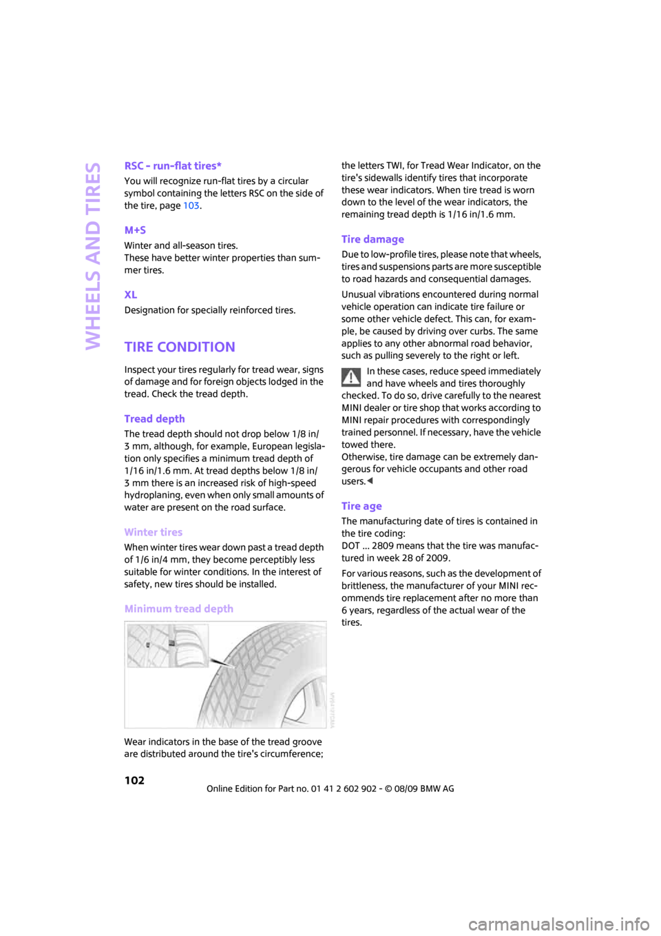
Wear indicators in the base of the tread groove
are distributed around the tire's circumference; the letters TWI, for Tread Wear Indicator, on the
tire's sidewalls identify tires that incorporate
these wear indicators. When tire tread is worn
down to the level of the wear indicators, the
remaining tread depth is 1/16 in/1.6 mm.
Tire damage
Due to low-profile tires, please note that wheels,
tires and suspensions parts are more susceptible
to road hazards and consequential damages.
Unusual vibrations encountered during normal
vehicle operation can indicate tire failure or
some other vehicle defect. This can, for exam-
ple, be caused by driving over curbs. The same
applies to any other abnormal road behavior,
such as pulling severely to the right or left.
In these cases, reduce speed immediately
and have wheels and tires thoroughly
checked. To do so, drive carefully to the nearest
MINI dealer or tire shop that works according to
MINI repair procedures with correspondingly
trained personnel. If necessary, have the vehicle
towed there.
Otherwise, tire damage can be extremely dan-
gerous for vehicle occupants and other road
users.<
Tire age
The manufacturing date of tires is contained in
the tire coding:
DOT ... 2809 means that the tire was manufac-
tured in week 28 of 2009.
For various reasons, such as the development of
brittleness, the manufacturer of your MINI rec-
ommends tire replacement after no more than
6 years, regardless of the actual wear of the
tires.
Page 108 of 160

Under the bonnet
106
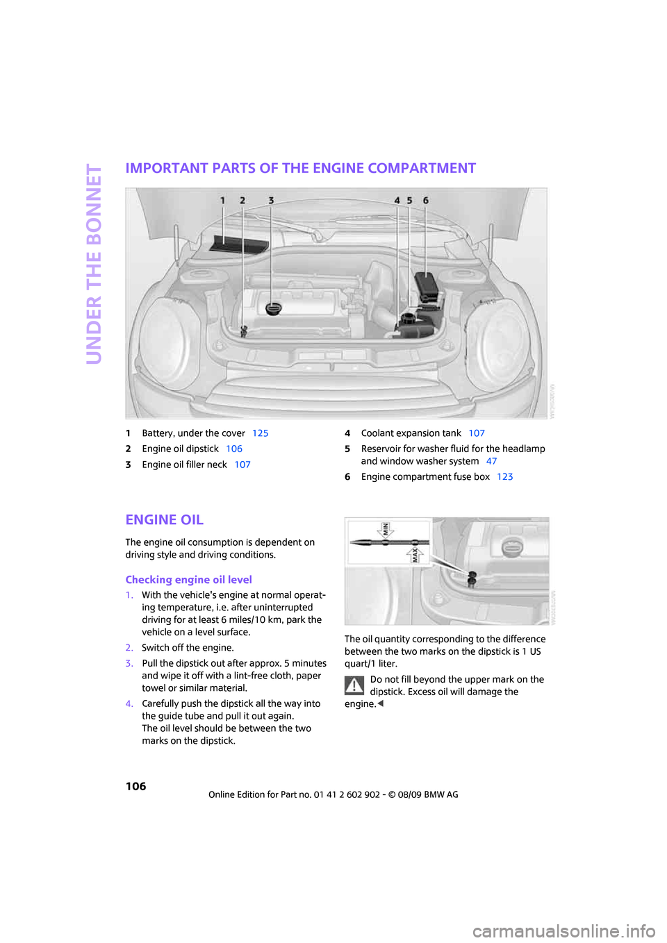
Important parts of the engine compartment
1Battery, under the cover125
2Engine oil dipstick106
3Engine oil filler neck1074Coolant expansion tank107
5Reservoir for washer fluid for the headlamp
and window washer system47
6Engine compartment fuse box123
Engine oil
The engine oil consumption is dependent on
driving style and driving conditions.
Checking engine oil level
1.With the vehicle's engine at normal operat-
ing temperature, i.e. after uninterrupted
driving for at least 6 miles/10 km, park the
vehicle on a level surface.
2.Switch off the engine.
3.Pull the dipstick out after approx. 5 minutes
and wipe it off with a lint-free cloth, paper
towel or similar material.
4.Carefully push the dipstick all the way into
the guide tube and pull it out again.
The oil level should be between the two
marks on the dipstick.The oil quantity corresponding to the difference
between the two marks on the dipstick is 1 US
quart/1 liter.
Do not fill beyond the upper mark on the
dipstick. Excess oil will damage the
engine.<
Page 116 of 160

Replacing components
114
Replacing components
Onboard vehicle tool kit
Your vehicle comes with an onboard vehicle tool
kit that varies with the equipment version; it is
stored underneath the level load floor.
>Mobility System with onboard vehicle tool
kit and tire change set
*118
>Tire change set with onboard vehicle tool kit
for space-saver spare tire121
Wiper blades
Changing the front wiper blades
1.Fold up the wiper arm.
2.Position the wiper blade horizontally.
3.Press the securing spring, arrow.
4.Unhook the wiper blade toward the wind-
shield.
5.Pull the wiper blade past the wiper arm
toward the top.
6.Insert the new wiper blade.7.Press into position until you hear it engage.
8.Fold down the wiper arm.
To avoid damage, make sure that the
wiper arms are against the windshield
before you open the bonnet.<
Changing the rear wiper blade
1.Fold out the wiper arm and hold it.
2.Press together the locking spring, arrow 1,
and fold out the wiper blade.
3.Pull the wiper blade away from and out of
the catch mechanism, arrow 2.
4.Press the new wiper blade into the fixture
until it engages audibly.
Lamps and bulbs
Lamps and bulbs make an essential contribution
to vehicle safety. They should, therefore, be
handled carefully. The manufacturer of your
MINI recommends having your MINI dealer per-
form any work that you do not feel competent to
perform yourself or that is not described here.
Never touch the glass of new bulbs with
your bare fingers, as even minute
amounts of contamination will burn into the
bulb's surface and reduce its service life. Use a
clean tissue, cloth or something similar, or hold
the bulb by its base.<
You can obtain a selection of replacement bulbs
at your MINI dealer.
Page 119 of 160

REFERENCEAT A GLANCE CONTROLS DRIVING TIPS MOBILITY
117
3.Screw out the upper bulb counterclockwise.
4.To insert the new bulb and replace the
cover, proceed in reverse order.
Replacing a fog lamp bulb
H8 bulb, 35 watts
1.Turn in the wheel.
2.Remove cover 2.
To do so, turn the cover counterclockwise.
3.Screw out the lower bulb counterclockwise.
4.To insert the new bulb and replace the
cover, proceed in reverse order.
Side turn signal indicators
5 watt bulb, W 5 W
1.Push the lamp with the ventilation grate for-
ward and remove.2.Screw out the bulb holder counterclockwise.
3.Pull out and replace the bulb.
4.To insert the new bulb and replace the
cover, proceed in reverse order.
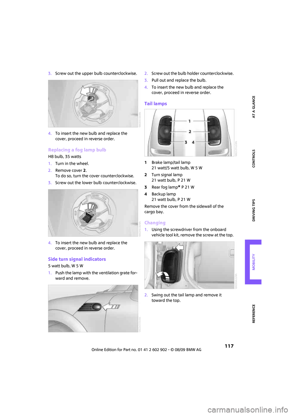
Tail lamps
1Brake lamp/tail lamp
21 watt/5 watt bulb, W 5 W
2Turn signal lamp
21 watt bulb, P 21 W
3Rear fog lamp
* P 21 W
4Backup lamp
21 watt bulb, P 21 W
Remove the cover from the sidewall of the
cargo bay.
Changing
1.Using the screwdriver from the onboard
vehicle tool kit, remove the screw at the top.
2.Swing out the tail lamp and remove it
toward the top.
Page 121 of 160

REFERENCEAT A GLANCE CONTROLS DRIVING TIPS MOBILITY
119
The Mobility System with tire change set and
onboard vehicle tool kit is located under the
floor mat or the level load floor in the cargo bay.
1Compressor
2Valve removal tool
3Wheel stud wrench
*
4Vehicle jack*
5Torx insert bit for screwdriver
6Flat screwdriver/Phillips screwdriver, towing
eyelet
7Hub cover remover
8Sealant bottle
Sealant and compressor
1Sealant bottle and adhesive label with speed
limit
2Filling hose
Note the use-by date on the sealant
bottle.<3Plug and cable for the socket in the vehicle
interior, page81
4Holder for the sealant bottle
5Compressor
6Pressure gauge for indicating the tire infla-
tion pressure
7On/off switch
8Release button for reducing the tire inflation
pressure
9Connection hose to connect the compressor
and sealant bottle or the compressor and
wheel
Connector, cable and connection hose are
stored in the compressor housing.
Using the Mobility System
To repair a tire puncture with the Mobility Sys-
tem, proceed as follows:
>Fill the tire with sealant
>Distribute the sealant
>Correct the tire inflation pressure
Filling the tire with sealant
Proceed in the specified order; otherwise,
sealant may emerge under high
pressure.<
1.Shake the sealant bottle.
2.Pull the connection hose9 out of the com-
pressor housing fully and screw it onto the
connector of the sealant bottle. Make sure
that the hose is not kinked.
3.Insert the sealant bottle on the compressor
housing in an upright position.
Page 122 of 160

Replacing components
120
4.Unscrew the dust cap from the valve of the
defective wheel and screw the filling hose 2
of the sealant bottle onto the valve.
5.Ensure that the compressor is switched off.
6.Insert the plug 3 into the lighter socket/
power socket in the vehicle interior,
page81.
7.With the engine running:
Switch on the compressor and let is run for
approx. 3 to 8 minutes to fill the tire with
sealant and achieve a tire inflation pressure
of approx. 26 psi/180 kPa.
When the tire is being filled with seal-
ant, the inflation pressure may spo-
radically reach approx. 73 psi/500 kPa. Do
not switch off the compressor in this
phase.<
Do not run the compressor for longer
than 10 minutes; otherwise, the
device will overheat and possibly be
damaged.<
8.Switch off the compressor.
If an air pressure of 26 psi/180 kPa is not
reached:
1.Unscrew the filling hose 2 from the wheel
and drive the vehicle forward and backward
approx. 33 ft/10 m to distribute the liquid
sealant in the tire evenly.
2.Inflate the tire again with the compressor.
If an inflation pressure of 26 psi/180 kPa
still cannot be reached, the tire is too
heavily damaged. Please contact the nearest
MINI dealer.<
Detach the connection hose 9 and filling hose 2
from the sealant bottle connection and tire
valve.Wrap the empty sealant bottle in suitable mate-
rial to avoid dirtying the cargo bay. Stow the
Mobility System back in the vehicle.
Distributing the sealant
Immediately drive approx. 3 mls/5 km to evenly
distribute the sealant.
Do not exceed speeds of 50 mph/
80 km/h.
If possible, do not drop below 10 mph/
20 km/h.<
Correcting the tire inflation pressure
1.After driving approx. 3 mls/5 km or ten min-
utes, stop at a suitable location.
2.Screw the connection hose 2 of the com-
pressor directly onto the tire valve.
3.Insert the plug 3 into the power socket in the
vehicle interior.
4.Correct the inflation pressure to 26 psi/
180 kPa. With the engine running:
>To increase the inflation pressure: switch on
the compressor. To check the current infla-
tion pressure, switch off the compressor.
Do not run the compressor for longer
than 10 minutes; otherwise, the
device will overheat and possibly be
damaged.<
>To decrease the inflation pressure: press the
release button 5.
If the tire cannot maintain the inflation
pressure, drive the vehicle again, refer to
Distributing the sealant. Then repeat steps
1to4.
If an inflation pressure of 26 psi/180 kPa still
cannot be reached, the tire is too heavily dam-
aged. Contact the nearest MINI dealer.<
Driving on
Do not exceed the permitted maximum
speed of 50 mph/80 km/h; doing so may
result in an accident.<
Replace the defective tire as soon as possible
and have the new wheel/tire assembly bal-
anced.
Have the Mobility System refilled.
Page 123 of 160

REFERENCEAT A GLANCE CONTROLS DRIVING TIPS MOBILITY
121
Changing wheels
Space-saver spare tire*
To change a space-saver spare tire, proceed as
follows:
>Remove the space-saver spare tire,
page121
>Prepare for tire change, page121
>Jack up vehicle, page122
>Mount space-saver spare tire, page122
>Tighten lug bolts, page122
>Drive with space-saver spare tire, page121
Tire change set for a space-saver
spare tire*
In vehicles with the space-saver spare tire, the
tire change set with the onboard vehicle tool kit
is located beneath the floor mat or level load
floor in the cargo bay.
1Folding chock and cover for defective wheel
2Vehicle jack
3Wheel stud wrench
4Hub cover remover
5Flat screwdriver/Phillips screwdriver
6Torx insert bit for screwdriver
7Towing eyelet
The onboard vehicle tool kit includes a pouch
with a plastic bag in which you can place the
damaged wheel.
Removing the space-saver spare tire
The space-saver spare tire is located under the
tire change set in the cargo bay.
1.Fold up the floor mat.
2.Unscrew the nut, arrow, and remove the
space-saver spare tire.
Driving with the space-saver spare tire
Drive cautiously and do not exceed a
speed of 50 mph/80 km/h. Changes may
occur in vehicle handling such as lower track sta-
bility during braking, longer braking distances
and changes in self-steering properties when
close to the handling limit. These properties are
more noticeable with winter tires.<
Only one space-saver spare tire may be
mounted at one time. Mount a wheel and
tire of the original size as soon as possible, to
avoid any safety risks.<
Check the tire inflation pressure at the ear-
liest opportunity and correct it if neces-
sary. Replace the defective tire as soon as possi-
ble and have the new wheel/tire assembly
balanced.<
Preparing for a tire change
Observe the safety precautions regarding
flat tires on page118.<
Additional safety measures when chang-
ing tires:
Only change the tire when parked on a surface
that is level, firm and not slippery.
The vehicle or the jack could slip sideways on
soft or slippery support surfaces, such as snow,
ice, flagstones, etc.
Page 127 of 160

REFERENCEAT A GLANCE CONTROLS DRIVING TIPS MOBILITY
125
Connecting jumper cables
Connect the jumper cables in the correct
order, so that no sparks which could cause
injury occur.<
1.Open the battery cover in the engine com-
partment to access the positive terminal of
your MINI.
2.Attach one terminal clamp of the plus/+
jumper cable to the positive terminal of the
battery or to a starting-aid terminal of the
vehicle providing assistance.
3.Attach the second terminal clamp of the
plus/+ jumper cable to the positive terminal
of the battery or a starting-aid terminal of
the vehicle to be started.
4.Attach one terminal clamp of the minus/–
jumper cable to the negative terminal of the
battery or to an engine or body ground of
the assisting vehicle.
Body ground in MINI:
5.Attach the second terminal clamp of the
minus/– jumper cable to the negative termi-
nal of the battery or to the engine or body
ground of the vehicle to be started.
Starting the engine
1.Start the engine of the donor vehicle and
allow it to run for a few minutes at slightly
increased idle speed.
2.Start the engine of the other vehicle in the
usual manner.
If the first start attempt is not successful,
wait a few minutes before another attempt
in order to allow the discharged battery to
recharge.
3.Let the engines run for a few minutes.
4.Disconnect the jumper cables by reversing
the above connecting sequence.
If necessary, have the battery checked and
recharged.
Never use spray fluids to start the
engine.<
Tow-starting,
towing away
Observe the applicable laws and regu-
lations for tow-starting and towing
vehicles.<
Do not transport any passengers other
than the driver in a vehicle that is being
towed.<
Using a tow fitting
The screw-in tow fitting must always be carried
in the car. It can be screwed in at the front or
rear of the MINI.
It is stored in the onboard vehicle tool kit in the
cargo bay underneath the cover on the right-
hand side, page114.
Use only the tow fitting provided with the
vehicle and screw it all the way in. Use the
tow fitting for towing on paved roads only. Avoid
lateral loading of the tow fitting, e.g. do not lift
the vehicle by the tow fitting. Otherwise, the tow
fitting and the vehicle could be damaged.<
Page 128 of 160

Giving and receiving assistance
126
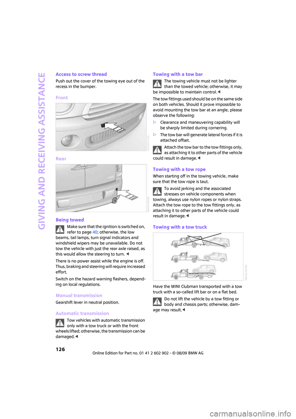
Access to screw thread
Push out the cover of the towing eye out of the
recess in the bumper.
Front
Rear
Being towed
Make sure that the ignition is switched on,
refer to page40; otherwise, the low
beams, tail lamps, turn signal indicators and
windshield wipers may be unavailable. Do not
tow the vehicle with just the rear axle raised, as
this would allow the steering to turn. <
There is no power assist while the engine is off.
Thus, braking and steering will require increased
effort.
Switch on the hazard warning flashers, depend-
ing on local regulations.
Manual transmission
Gearshift lever in neutral position.
Automatic transmission
Tow vehicles with automatic transmission
only with a tow truck or with the front
wheels lifted; otherwise, the transmission can be
damaged.<
Towing with a tow bar
The towing vehicle must not be lighter
than the towed vehicle; otherwise, it may
be impossible to maintain control.<
The tow fittings used should be on the same side
on both vehicles. Should it prove impossible to
avoid mounting the tow bar at an angle, please
observe the following:
>Clearance and maneuvering capability will
be sharply limited during cornering.
>The tow bar will generate lateral forces if it is
attached offset.
Attach the tow bar to the tow fittings only,
as attaching it to other parts of the vehicle
could result in damage.<
Towing with a tow rope
When starting off in the towing vehicle, make
sure that the tow rope is taut.
To avoid jerking and the associated
stresses on vehicle components when
towing, always use nylon ropes or nylon straps.
Attach the tow rope to the tow fittings only, as
attaching it to other parts of the vehicle could
result in damage.<
Towing with a tow truck
Have the MINI Clubman transported with a tow
truck with a so-called lift bar or on a flat bed.
Do not lift the vehicle by a tow fitting or
body and chassis parts; otherwise, dam-
age may result.<
Page 129 of 160

REFERENCEAT A GLANCE CONTROLS DRIVING TIPS MOBILITY
127
Tow-starting
Avoid tow-starting the vehicle whenever possi-
ble; instead, jump-start the engine, page124.
Vehicles with a catalytic converter should only
be tow-started when the engine is cold, vehicles
with an automatic transmission cannot be tow-
started at all.
1.Switch on hazard warning flashers, comply
with local regulations.
2.Switch on the ignition, page40.
3.Shift into 3rd gear.
4.Have the vehicle tow-started with the clutch
completely depressed and then slowly
release the clutch. After the engine starts,
immediately depress the clutch completely
again.
5.Stop at a suitable location, remove the tow
bar or rope and switch off the hazard warn-
ing flashers.
6.Have the vehicle checked.