MINI Clubman 2011 Owner's Manual (Mini Connected)
Manufacturer: MINI, Model Year: 2011, Model line: Clubman, Model: MINI Clubman 2011Pages: 256, PDF Size: 3.75 MB
Page 221 of 256

Giving and receiving assistanceMOBILITY
219
Giving and receiving assistance
Roadside Assistance
Roadside Assistance is available by phone
24 hours a day in many countries. You can
receive assistance there in the event of an emer-
gency.
First aid pouch*
Some of the articles co ntained in the first aid
pouch have a limited se rvice life. Therefore,
check the expiration dates of the contents regu-
larly and replace any items in good time, if nec-
essary.
The first aid pouch is located on the rear cargo
well by the left side trim panel or under the flat
load floor.
Warning triangle*
In the cargo area under the loading sill. Open the center lock to take it out.
Jump-starting
If the car's own battery is flat, your MINI's engine
can be started by connecting two jumper cables
to another vehicle's battery. You can also use
the same method to help start another vehicle.
Only use jumper cables with fully-insulated
clamp handles.
Do not touch any electrically live parts
w hen the e ngin e is run ning, or a fatal acci-
dent may occur. Carefully adhere to the follow-
ing sequence, both to prevent damage to one or
both vehicles, and to guard against possible per-
sonal injuries. <
Preparation
1.Check whether the battery of the other vehi-
cle has a voltage of 12 volts and approxi-
mately the same capacitance in Ah. This
information can be found on the battery.
2. Switch off the engine of the support vehicle.
3. Switch off any consumers in both vehicles.
There must not be any contact between
the bodies of the two vehicles; otherwise,
there is a danger of shorting. <
Connecting jumper cables
Connect the jumper cables in the correct
o r d e r , s o t h a t n o s parks which could cause
injury occur. <
Page 222 of 256

MOBILITYGiving and receiving assistance
220
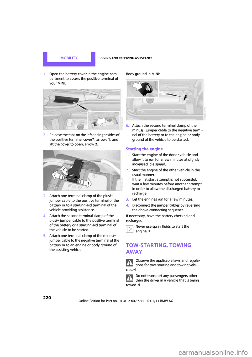
1.Open the battery cover in the engine com-
partment to access the positive terminal of
your MINI.
2. Release the tabs on the left and right sides of
the positive terminal cover
*, arrows 1, and
lift the cover to open, arrow 2.
3. Attach one terminal clamp of the plus/+
jumper cable to the positive terminal of the
battery or to a starting-aid terminal of the
vehicle providing assistance.
4. Attach the second terminal clamp of the
plus/+ jumper cable to the positive terminal
of the battery or a starting-aid terminal of
the vehicle to be started.
5. Attach one terminal clamp of the minus/–
jumper cable to the negative terminal of the
battery or to an engine or body ground of
the assisting vehicle. Body ground in MINI:
6.
Attach the second te rminal clamp of the
minus/– jumper cable to the negative termi-
nal of the battery or to the engine or body
ground of the vehicle to be started.
Starting the engine
1. Start the engine of the donor vehicle and
allow it to run for a few minutes at slightly
increased idle speed.
2. Start the engine of the other vehicle in the
usual manner.
If the first start attempt is not successful,
wait a few minutes before another attempt
in order to allow the discharged battery to
recharge.
3. Let the engines run for a few minutes.
4. Disconnect the jumper cables by reversing
the above connecting sequence.
If necessary, have the battery checked and
recharged. Never use spray fluids to start the
engine. <
Tow-starting, towing
away
Observe the applicable laws and regula-
tions for tow-starting and towing vehi-
cles. <
Do not transport any passengers other
than the driver in a vehicle that is being
towed. <
Page 223 of 256

Giving and receiving assistanceMOBILITY
221
Using a tow fitting
The screw-in tow fitting must always be carried
in the car. It can be screwed in at the front or
rear of the MINI.
It is stored in the onboard vehicle toolkit in the
cargo area underneath the cover on the right-
hand side, page 208.
Use only the tow fitting provided with the
vehicle and screw it all the way in. Use the
tow fitting for towing on paved roads only. Avoid
lateral loading of the tow fitting, e.g. do not lift
the vehicle by the tow fitting. Otherwise, the tow
fitting and the vehicle could be damaged. <
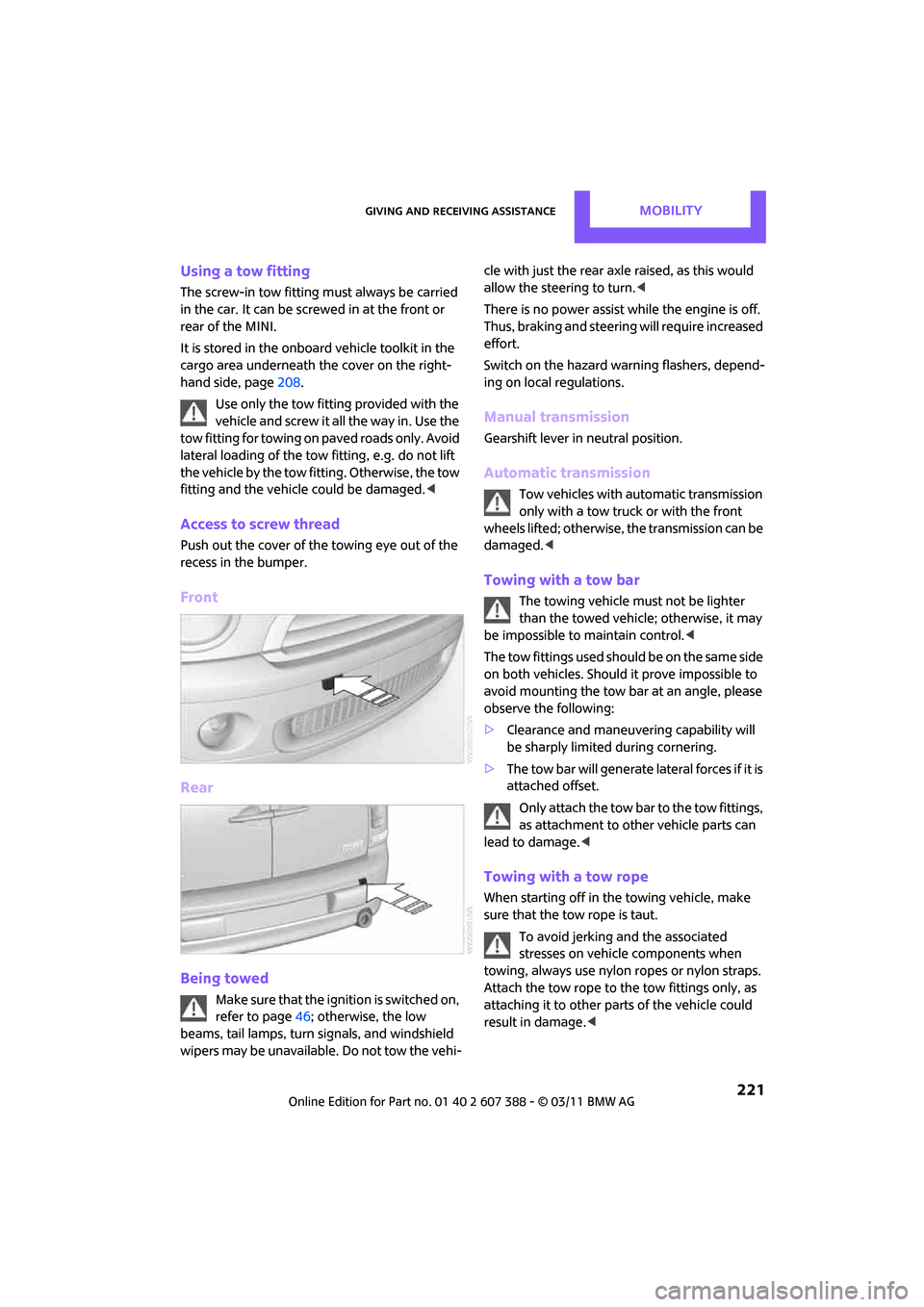
Access to screw thread
Push out the cover of the towing eye out of the
recess in the bumper.
Front
Rear
Being towed
M a k e s u r e t h a t t h e i g n i t i o n i s s w i t c h e d o n ,
refer to page46; otherwise, the low
beams, tail lamps, turn signals, and windshield
wipers may be unavailable. Do not tow the vehi- cle with just the rear ax
le raised, as this would
allow the steering to turn. <
There is no power assist while the engine is off.
Thus, braking and steering will require increased
effort.
Switch on the hazard warning flashers, depend-
ing on local regulations.
Manual transmission
Gearshift lever in neutral position.
Automatic transmission
Tow vehicles with automatic transmission
only with a tow truck or with the front
wheels lifted; otherwise, the transmission can be
damaged. <
Towing with a tow bar
The towing vehicle must not be lighter
than the towed vehicle; otherwise, it may
be impossible to maintain control. <
The tow fittings used should be on the same side
on both vehicles. Should it prove impossible to
avoid mounting the tow bar at an angle, please
observe the following:
> Clearance and maneuvering capability will
be sharply limited during cornering.
> The tow bar will generate lateral forces if it is
attached offset.
Only attach the tow bar to the tow fittings,
as attachment to ot her vehicle parts can
lead to damage. <
Towing with a tow rope
When starting off in the towing vehicle, make
sure that the tow rope is taut.
To avoid jerking and the associated
stresses on vehicle components when
towing, always use nylon ropes or nylon straps.
Attach the tow rope to the tow fittings only, as
attaching it to other parts of the vehicle could
result in damage. <
Page 224 of 256

MOBILITYGiving and receiving assistance
222
Towing with a tow truck
Have the MINI Clubman transported with a tow
truck with a so-called lift bar or on a flat bed.Do not lift the vehicle by a tow fitting or
body and chassis parts; otherwise, dam-
age may result. <
Tow-starting
Avoid tow-starting the vehicle whenever possi-
ble; instead, jump-start the engine, page 219.
Vehicles with a catalyti c converter should only
be tow-started when the engine is cold, vehicles
with an automatic transmission cannot be tow-
started at all.
1. Switch on hazard warning flashers, comply
with local regulations.
2. Switch on the ignition, page 46.
3. Shift into 3rd gear.
4. Have the vehicle tow-started with the clutch
completely depressed and then slowly
release the clutch. Afte r the engine starts,
immediately depress the clutch completely
again.
5. Stop at a suitable lo cation, remove the tow
bar or rope and switch off the hazard warn-
ing flashers.
6. Have the vehicle checked.
Page 225 of 256

Giving and receiving assistanceMOBILITY
223
Page 226 of 256

Find Me.
Page 227 of 256

AT A GLANCE
CONTROLS
DRIVING TIPS
NAVIGATION
ENTERTAINMENT
Communications
MOBILITY
REFERENCE
Page 228 of 256

REFERENCETechnical data
226
Technical data
Engine data
In the technical data, only the values that differ from the Cooper S are shown for the
John Cooper Works.
Cooper Cooper SJohn Cooper Works
Displacementcu in/
cm μ 97.5/
1,598 97.5/
1,598 97.5/
1,598
Number of cylinders 44 4
Maximum power
output hp
121181 208
At engine speed rpm 6,0005,500 6,000
Maximum torque
with overboost lb ft/
Nm114/155
– 177/240
192/260 192/260
207/280
At engine speed
with overboost rpm
4,250
– 1,600-5,000
1,730-4,500 1,850-5,600
2,000-5,100
Overboost briefly raises the maximum torque at high rates of acceleration, e. g. when passing.
Page 229 of 256

Technical dataREFERENCE
227
Dimensions
All dimensions in inches/mm. Minimum turning radius dia.: 36 ft in/11.0 m.
Information after the semicolon: different values for MINI Cooper S.
Page 230 of 256

REFERENCETechnical data
228
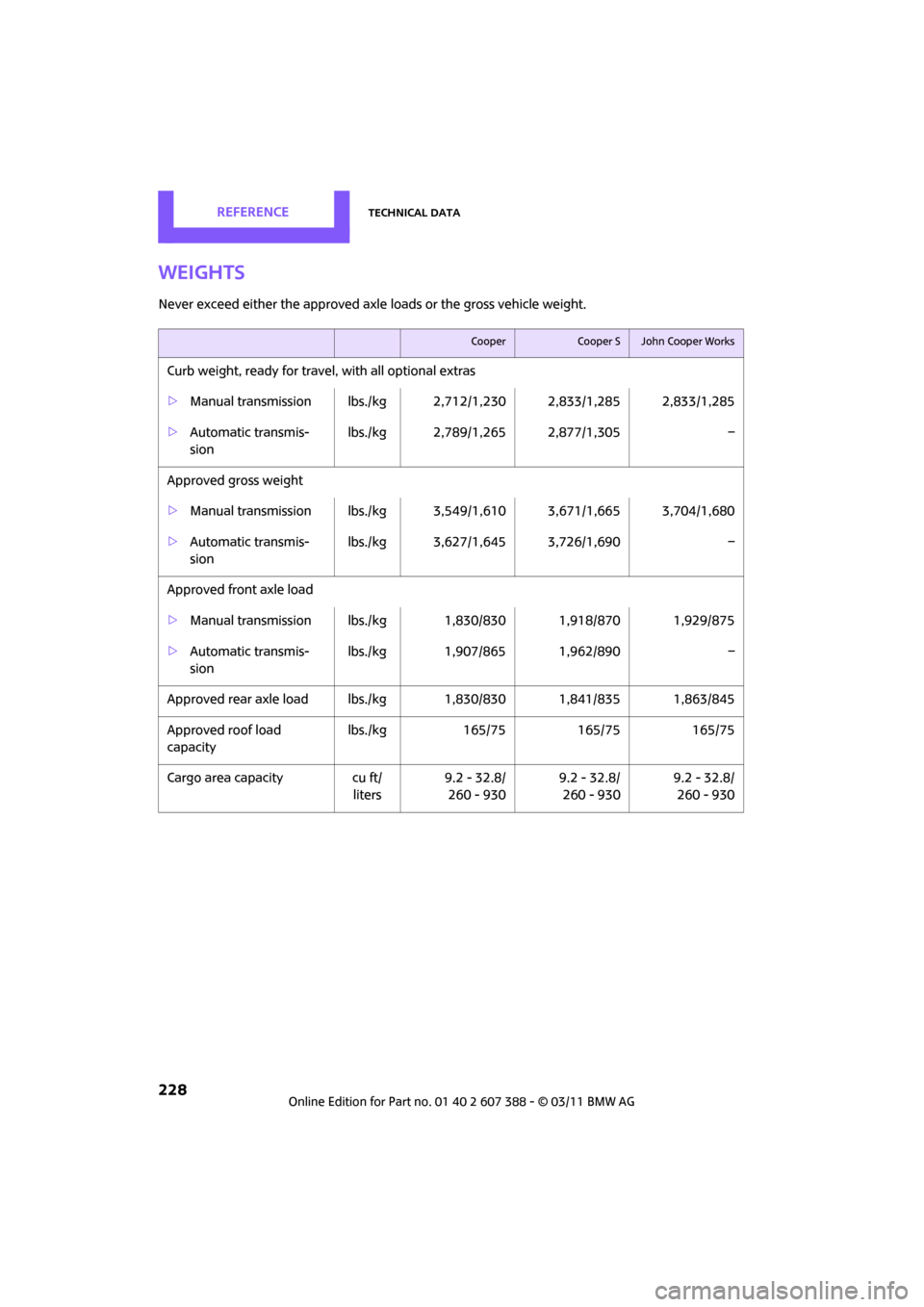
Weights
Never exceed either the approved axle loads or the gross vehicle weight.
CooperCooper SJohn Cooper Works
Curb weight, ready for travel, with all optional extras
> Manual transmission lbs./kg 2,7 12/1,230 2,833/1,285 2,833/1,285
> Automatic transmis-
sion lbs./kg 2,789/1,265 2,877/1,305 –
Approved gross weight
> Manual transmission lbs./kg 3,5 49/1,610 3,671/1,665 3,704/1,680
> Automatic transmis-
sion lbs./kg 3,627/1,645 3,726/1,690 –
Approved front axle load
> Manual transmission lbs./k g 1,830/830 1,918/870 1,929/875
> Automatic transmis-
sion lbs./kg 1,907/865 1,962/890
–
Approved rear axle load lb s./kg 1,830/830 1,841/835 1,863/845
Approved roof load
capacity lbs./kg
165/75165/75 165/75
Cargo area capacity cu ft/
liters 9.2 - 32.8/
260 - 930 9.2 - 32.8/
260 - 930 9.2 - 32.8/
260 - 930