check engine MINI Clubman 2016 (Mini Connected) Owner's Guide
[x] Cancel search | Manufacturer: MINI, Model Year: 2016, Model line: Clubman, Model: MINI Clubman 2016Pages: 246, PDF Size: 5.21 MB
Page 217 of 246

Starting aid terminals
WARNING
If the jumper cables are connected in the
incorrect order, sparks formation can occur.
There is risk of injuries. Pay attention to the cor‐
rect order during connection.◀
The starting aid terminal in the engine com‐
partment acts as the battery's positive terminal.
Open the cover of the starting aid terminal.
The body ground or a special nut acts as the
battery negative terminal.
Connecting the cables
1.Pull off the lid of the starting aid terminal.2.Attach one terminal clamp of the positive
jumper cable to the positive terminal of the
battery, or to the corresponding starting aid
terminal of the vehicle providing assistance.
3.Attach the terminal clamp on the other end
of the cable to the positive terminal of the
battery, or to the corresponding starting aid
terminal of the vehicle to be started.
4.Attach one terminal clamp of the negative
jumper cable to the negative terminal of
the battery, or to the corresponding engine
or body ground of assisting vehicle.
5.Attach the second terminal clamp to the
negative terminal of the battery, or to the
corresponding engine or body ground of
the vehicle to be started.
Starting the engine
Never use spray fluids to start the engine.
1.Start the engine of the assisting vehicle and
let it run for several minutes at an increased
idle speed.
2.Start the engine of the vehicle that is to be
started in the usual way.
If the first starting attempt is not successful,
wait a few minutes before making another
attempt in order to allow the discharged
battery to recharge.
3.Let both engines run for several minutes.4.Disconnect the jumper cables in the reverse
order.
Check the battery and recharge if needed.
Tow-starting and towing
Information
WARNING
Due to system limits, individual functions
can malfunction during tow-starting/towing
with the Intelligent Safety systems activated,
for example approach control warning with
light braking function. There is risk of an acci‐
dent. Switch all Intelligent Safety systems off
prior to tow-starting/towing.◀
Switching off Intelligent Safety systems, refer to
page 110.
Seite 217Breakdown assistanceMOBILITY217
Online Edition for Part no. 01 40 2 964 571 - X/15
Page 220 of 246

▷Use only the tow fitting provided with the
vehicle and screw it all the way in.
▷Use the tow fitting for towing on paved
roads only.
▷Use tow fitting located in the front only for
positioning the vehicle.
▷Avoid lateral loading of the tow fitting, for
example, do not lift the vehicle by the tow
fitting.
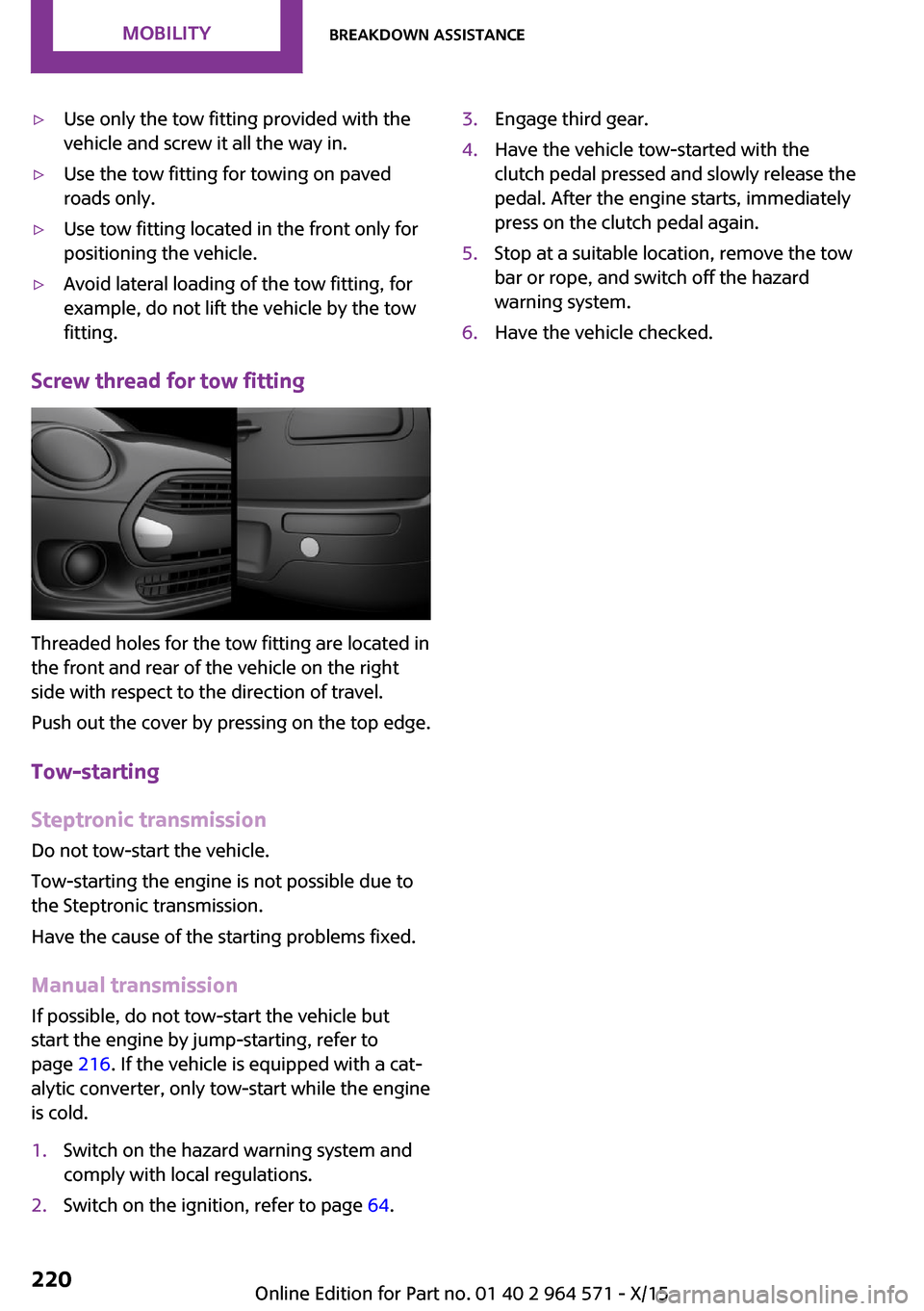
Screw thread for tow fitting
Threaded holes for the tow fitting are located in
the front and rear of the vehicle on the right
side with respect to the direction of travel.
Push out the cover by pressing on the top edge.
Tow-starting
Steptronic transmission
Do not tow-start the vehicle.
Tow-starting the engine is not possible due to
the Steptronic transmission.
Have the cause of the starting problems fixed.
Manual transmission
If possible, do not tow-start the vehicle but
start the engine by jump-starting, refer to
page 216. If the vehicle is equipped with a cat‐
alytic converter, only tow-start while the engine
is cold.
1.Switch on the hazard warning system and
comply with local regulations.
2.Switch on the ignition, refer to page 64.3.Engage third gear.4.Have the vehicle tow-started with the
clutch pedal pressed and slowly release the
pedal. After the engine starts, immediately
press on the clutch pedal again.
5.Stop at a suitable location, remove the tow
bar or rope, and switch off the hazard
warning system.
6.Have the vehicle checked.Seite 220MOBILITYBreakdown assistance220
Online Edition for Part no. 01 40 2 964 571 - X/15
Page 222 of 246

Manual transmission:1.Drive into the car wash.2.Shift to neutral.3.Switch the engine off.4.Switch on the ignition.
Steptronic transmission:
1.Drive into the car wash.2.Engage selector lever position N.3.Make sure that the parking brake is re‐
leased.
4.Press the Start/Stop button to switch off the
engine.
In this way, the ignition remains switched
on, and two Check-Control messages are
displayed.
A signal sounds when you leave the vehicle
while in selector lever position N.
The vehicle cannot be locked from the outside
when in selector lever position N. A signal is
sounded when an attempt is made to lock the
vehicle.
To start the engine with manual transmission:
1.Press on the clutch pedal.2.Press the Start/Stop button.
To start the engine with Steptronic transmis‐
sion:
1.Depress the brake pedal.2.Press the Start/Stop button.
Headlights
▷Do not rub dry and do not use abrasive or
acidic cleansers.
▷Soak areas that have been dirtied e. g.,
from insects, with shampoo and wash off
with water.
▷Thaw ice with de-icing spray; do not use an
ice scraper.
After washing the vehicle
After washing the vehicle, apply the brakes
briefly to dry them; otherwise, braking action
can be reduced and corrosion of the brake
discs can occur.
Completely remove all residues on the win‐
dows, to minimize loss of visibility due to
smearing and to reduce wiper noises and wiper
blade wear.
Vehicle care
Car care products
The manufacturer of your vehicle recommends
using care and cleaning products from MINI.
WARNING
Cleansers can contain substances that are
dangerous and harmful to your health. There is
risk of injuries. When cleaning the interior, open
the doors or windows. Only use products in‐
tended for cleaning vehicles. Follow the instruc‐
tions on the container.◀
Vehicle paint
Regular care contributes to driving safety and
value retention. Environmental influences in
areas with elevated air pollution or natural con‐
taminants, such as tree resin or pollen can af‐
fect the vehicle's paintwork. Tailor the fre‐
quency and extent of your car care to these
influences.
Aggressive substances such as spilled fuel, oil,
grease or bird droppings must be removed im‐
mediately to prevent the finish from being al‐
tered or discolored.
Leather care
Remove dust from the leather often, using a
cloth or vacuum cleaner.
Otherwise, particles of dust and road grime
chafe in pores and folds, and lead to increased
Seite 222MOBILITYCare222
Online Edition for Part no. 01 40 2 964 571 - X/15
Page 237 of 246

Camera-based cruise con‐
trol 121
Camera lenses, care 224
Camera, rearview cam‐
era 132
Can holder, see Cu‐
pholder 156
Car battery 213
Car care products 222
Care, displays 224
Care, vehicle 222
Cargo area 152
Cargo area, adapting size 157
Cargo area door, see split
doors 40
Cargo area, enlarging 153
Cargo area, storage compart‐
ments 157
Cargo cover 152
Cargo, securing 166
Cargo straps, securing
cargo 166
Car key, see Remote con‐
trol 34
Carpet, care 224
Car wash 221
Catalytic converter, see Hot
exhaust system 163
CBS Condition Based Serv‐
ice 201
Center armrest 156
Center console 16
Central instrument cluster,
LED ring 92
Central locking system 40
Central screen, refer to Control
Display 18
Changes, technical, refer to
Own Safety 7
Changing parts 203
Changing wheels 212
Changing wheels/tires 187
Chassis number, see vehicle
identification number 10
Check Control 80
Checking the oil level elec‐
tronically 195
Children, seating position 60
Children, transporting
safely 60
Child restraint fixing sys‐
tem 60
Child restraint fixing system
LATCH 62
Child restraint fixing systems,
mounting 61
Child safety locks 63
Child seat, mounting 61
Child seats 60
Chrome parts, care 223
Cigarette lighter 150
Cleaning, displays 224
Climate control 139, 141
Clock 84
Closing/opening via door
lock 39
Closing/opening with remote
control 37
Clothes hooks 157
Coasting 172
Coasting with engine decou‐
pled, coasting 172
Coasting with idling en‐
gine 172
Combination switch, see Turn
signals 70
Combi switch, see wiper sys‐
tem 71
Comfort Access 41
Compartments in the
doors 156
Compass 148
Compressor 189
Condensation on win‐
dows 143
Condensation under the vehi‐
cle 164
Condition Based Service
CBS 201
Configuring driving pro‐
gram 120
Confirmation signal 44
Control Display 18
Control Display, settings 91
Controller 19
Control systems, driving stabil‐
ity 117
Convenient opening 38
Coolant 199
Cooling function 140, 142
Cooling, maximum 142
Cooling system 199
Cornering lamp 98
Corrosion on brake discs 164
Cosmetic mirror 150
Courtesy lamps during unlock‐
ing 37
Courtesy lamps with the vehi‐
cle locked 38
Cruise control 127
Cruise control, active 121
Cruising range 85
Cupholder 156
Current fuel consumption 85
D
Damage, tires 186
Damping control, dy‐
namic 119
Data, technical 228
Date 84
Daytime running lights 98
Defrosting, see defrosting the
windows 141
Defrosting, see Windows, de‐
frosting 143
Defrosting the windows 141
Dehumidifying, air 140, 142
Deleting personal data 24
Deletion of personal data 24
Destination distance 89
Digital clock 84
Digital compass 148
Dimensions 228
Dimmable exterior mirrors 58
Dimmable interior mirror 59
Seite 237Everything from A to ZREFERENCE237
Online Edition for Part no. 01 40 2 964 571 - X/15
Page 238 of 246

Direction indicator, see Turn
signals 70
Display, electronic, instrument
cluster 80
Display, engine tempera‐
ture 89
Display lighting, see Instru‐
ment lighting 99
Displays 79
Displays, cleaning 224
Disposal, coolant 200
Disposal, vehicle battery 214
Distance control, see PDC 129
Distance to destination 89
Divided screen view, split
screen 23
Door lock, see Remote con‐
trol 34
Drive mode, GREEN
Mode 169
Drive-off assistant 120
Drive-off assistant, see
DSC 117
Driving Dynamics Control 119
Driving Excitement, SPORT 90
Driving instruction, GREEN
Mode 171
Driving instructions, break-
in 162
Driving mode 119
Driving notes, general 163
Driving stability control sys‐
tems 117
Driving style analysis 173
Driving tips 163
DSC Dynamic Stability Con‐
trol 117
DTC Dynamic Traction Con‐
trol 118
Dynamic Damping Con‐
trol 119
Dynamic Stability Control
DSC 117
Dynamic Traction Control
DTC 118
E
Electronic displays, instrument
cluster 80
Electronic oil measure‐
ment 195
Electronic Stability Program
ESP, see DSC 117
Emergency detection, remote
control 35
Emergency release, fuel filler
flap 178
Emergency start function, en‐
gine start 35
Emergency wheel, compact
wheel, see Emergency
wheel 212
Energy Control 85
Engine, automatic Start/Stop
function 66
Engine, automatic switch-
off 66
Engine compartment 193
Engine compartment, working
in 193
Engine coolant 199
Engine idling when driving,
coasting 172
Engine oil 195
Engine oil, adding 196
Engine oil additives 197
Engine oil change 197
Engine oil filler neck 196
Engine oil types, alterna‐
tive 197
Engine oil types, suitable 197
Engine start during malfunc‐
tion 35
Engine start, jump-start‐
ing 216
Engine start, see Starting the
engine 65
Engine stop 65
Engine temperature, dis‐
play 89
Entering a car wash 221
Equipment, interior 146
Error displays, see Check Con‐
trol 80
ESP Electronic Stability Pro‐
gram, see DSC 117
Exchanging wheels/tires 187
Exhaust system 163
Exterior mirror, automatic
dimming feature 58
Exterior mirrors 57
External start 216
External temperature dis‐
play 84
External temperature warn‐
ing 84
Eyes for securing cargo 166
F
Failure message, see Check
Control 80
False alarm, see Unintentional
alarm 45
Fan, see Air flow 140, 143
Favorites buttons, onboard
monitor 24
Filler neck for engine oil 196
Fine wood, care 223
First-aid kit 216
Flat tire, changing wheels 212
Flat Tire Monitor FTM 108
Flat tire, repairing 188
Flat tire, Tire Pressure Monitor
TPM 104
Flat tire, warning
lamp 105, 108
Flooding 163
Floor carpet, care 224
Floor mats, care 224
Fogged up windows 141
Folding back rear seat back‐
rests 153
Fold-out position, windshield
wipers 73
Foot brake 163
Front airbags 101
Seite 238REFERENCEEverything from A to Z238
Online Edition for Part no. 01 40 2 964 571 - X/15
Page 243 of 246

Steptronic transmission 75
Stopping the engine 65
Storage compartments 155
Storage, tires 188
Storing the vehicle 224
Suitable engine oil types 197
Summer tires, tread 186
Sun visor 150
Supplementary text mes‐
sages 83
Switch for Dynamic Driv‐
ing 119
Switch-on times, parked-car
ventilation 145
Switch, see Cockpit 14
Symbols 6
Symbols in the status field 23
T
Tachometer 84
Tailgate, see split doors 40
Tail lamps 207
Technical changes, refer to
Own Safety 7
Technical data 228
Temperature, air condi‐
tioner 140
Temperature, automatic cli‐
mate control 142
Temperature display for exter‐
nal temperature 84
Temperature, engine 89
Tempomat, see camera-based
cruise control 121
Terminal, starting aid 217
Text messages, supplemen‐
tary 83
Theft alarm system, see Alarm
system 44
Thigh support 52
Tilt alarm sensor 45
Time of arrival 89
Tire damage 186
Tire identification marks 184
Tire inflation pressure 182
Tire inflation pressure moni‐
tor, refer to FTM 108
Tire Pressure Monitor
TPM 104
Tires, changing 187
Tire sealant 189
Tires, everything on wheels
and tires 182
Tires, run-flat tires 188
Tire tread 186
Tone, refer to Integrated
Owner's Manual
Tools 203
Total vehicle weight 229
Touchpad 21
Towing 217
Tow-starting 217
TPM Tire Pressure Moni‐
tor 104
Traction control 118
TRACTION drive mode, driving
dynamics 118
Transmission lock, releasing
manually 77
Transmission, manual trans‐
mission 74
Transmission, see Steptronic
transmission 75
Transporting children
safely 60
Tread, tires 186
Triple turn signal activa‐
tion 70
Trip odometer 84
Trip onboard computer 90
Trip recorder, see Trip odome‐
ter 84
Turning circle lines, rearview
camera 133
Turn signal, front 205
Turn signal, side 211
Turn signals, operation 70
Turn signals, rear, bulb re‐
placement 207
U
Unintentional alarm 45
Units of measurement 92
Universal remote control 146
Unlock button, Steptronic
transmission 75
Unlocking/locking via door
lock 39
Unlocking/locking with re‐
mote control 37
Unlocking, settings 43
Updates made after the edito‐
rial deadline 7
Upholstery care 223
USB interface 151
V
Vanity mirror 150
Vehicle battery 213
Vehicle battery, replacing 214
Vehicle, break-in 162
Vehicle care 222
Vehicle features and op‐
tions 7
Vehicle identification num‐
ber 10
Vehicle jack 212
Vehicle paint 222
Vehicle storage 224
Vehicle wash 221
Ventilation 144
Ventilation, see Parked-car
ventilation 144
VIN, see vehicle identification
number 10
Voice activation system 26
W
Warning and indicator lamps,
see Check Control 80
Warning displays, see Check
Control 80
Seite 243Everything from A to ZREFERENCE243
Online Edition for Part no. 01 40 2 964 571 - X/15