window MINI COOPER 2003 User Guide
[x] Cancel search | Manufacturer: MINI, Model Year: 2003, Model line: COOPER, Model: MINI COOPER 2003Pages: 148, PDF Size: 3.17 MB
Page 72 of 148

70
AUTOMATIC CLIMATE CONTROL
*
1Air onto the windshield and onto the
side windows
2Air for the upper body area72
3Air for the front and rear footwells
4Rear window defroster and windshield
heating715Interior temperature sensor – please
keep clear and unobstructed
6Recirculated air mode71
7Air conditioner68
8Automatic air distribution and supply71
9Switching the automatic climate control
on/off7110 Temperature71
11 Display for temperature and air
supply71
12 Blower for air supply71
13 Defrosting and demisting the wind-
shield and side windows69
14 Individual air distribution72
ba.book Seite 70 Montag, 5. August 2002 8:09 20
ProCarManuals.com
Page 73 of 148

71
OVERVIEW REPAIRS OPERATIONCONTROLS DATA INDEX
AUTOMATIC CLIMATE CONTROL
*
Automatic air distribution and supply
Automatic program (AUTO):
Indicator lamp lights up.
Automatic adjustment of the air distribution
and supply, and adaptation of the specified
temperatures to external influences, i.e. out-
side temperature and sunlight.
In the automatic program (AUTO), the air
conditioner is activated automatically.
Switching the automatic climate
control on/off
The blower, heating and air condi-
tioner are switched off.
To switch the automatic climate control on
again: Press any button of the automatic
climate control.
Air conditioning
Air conditioner switched on:
Indicator lamp lights up.
The air is cooled and dehumidified and –
depending on the temperature setting –
rewarmed.
In the automatic program (AUTO), the air
conditioner is activated automatically.
After the engine start, the windshield may
fog over briefly. Switching on the air condi-
tioner reduces condensation on the windows.
Condensation forms in the air condi-
tioner system during operation, and
then exits under the vehicle. Traces of con-
densed water on the ground are therefore
normal.<
Recirculated air mode
Supply of outside air into the vehi-
cle is blocked: Indicator lamp lights
up.
The air within the vehicle is recirculated.
In the automatic program (AUTO) in hot
weather conditions, the recirculated air
mode is activated temporarily to enable
faster cooling.
Do not run the recirculated air mode
for longer than approx. 30 minutes,
as otherwise the air quality in the interior
will deteriorate.<
If the windows fog up in the recircu-
lated air mode, turn the recirculated
air mode off and if necessary increase the
air supply.<
Rear window defroster and windshield
heating*
Rear window defroster and wind-
shield heating switched on:
Indicator lamp lights up.
As long as the indicator lamp is lit, the
heating operates at high power output –
rapid defrosting.
Indicator lamp goes out.
The heating continues to run with reduced
power output and then switches itself off
automatically.Temperature
Setting the temperature:
Move or turn the wheel in the
appropriate direction to increase
the temperature step by step.
The figures in the display provide a general
indication of interior temperature. When
you start the vehicle, the system ensures
that the selected temperature is achieved
as quickly as possible and then maintained.
Permanent heating with maximum
power output at temperature selec-
tion HI. Permanent cooling at LO.<
Air supply
Press the left or right half of the
button: the air supply varies.
ba.book Seite 71 Montag, 5. August 2002 8:09 20
ProCarManuals.com
Page 74 of 148
72
AUTOMATIC CLIMATE CONTROL
*
Defrosting and demisting windows
Press the button briefly.
The indicator lamp flashes.
Ice and condensation are removed from the
rear window/windshield and side
windows.
The rear window defroster/windshield
heating is switched on automatically. It can
be switched off again separately.
Press the button for a longer period.
Only air to the windshield.
Individual air distribution
Combine the air distribution
yourself. This switches off the
automatic program.
Draft-free ventilation Air supply for the upper body area:
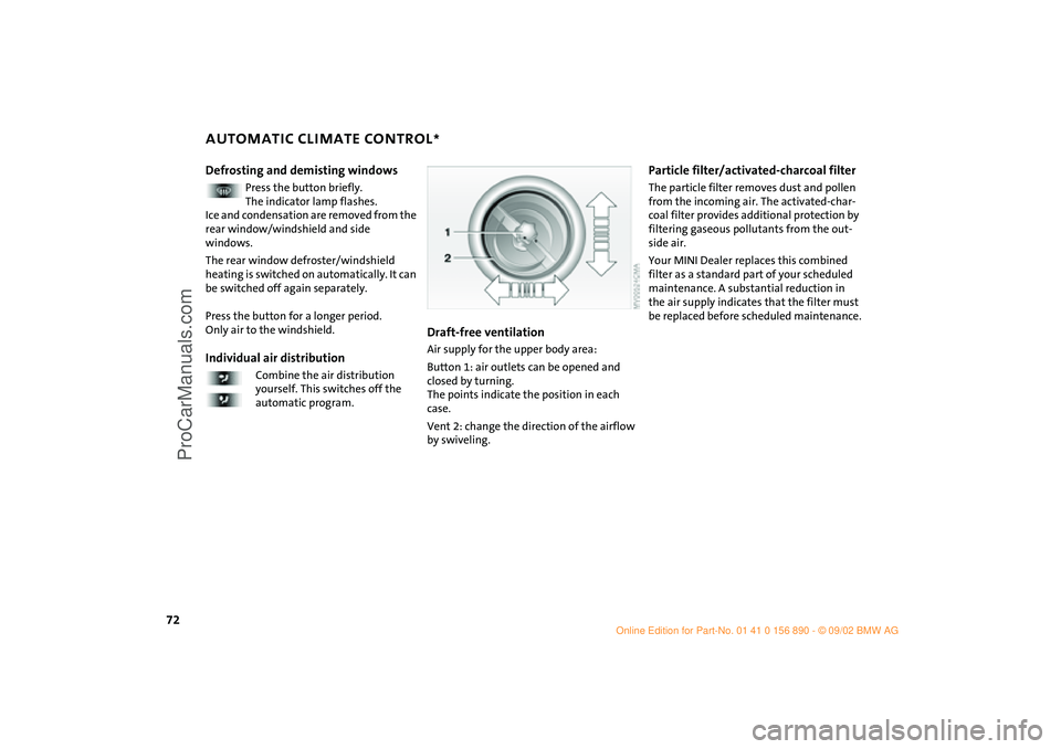
Button 1: air outlets can be opened and
closed by turning.
The points indicate the position in each
case.
Vent 2: change the direction of the airflow
by swiveling.
Particle filter/activated-charcoal filterThe particle filter removes dust and pollen
from the incoming air. The activated-char-
coal filter provides additional protection by
filtering gaseous pollutants from the out-
side air.
Your MINI Dealer replaces this combined
filter as a standard part of your scheduled
maintenance. A substantial reduction in
the air supply indicates that the filter must
be replaced before scheduled maintenance.
ba.book Seite 72 Montag, 5. August 2002 8:09 20
ProCarManuals.com
Page 103 of 148
101
OVERVIEW REPAIRSOPERATIONCONTROLS DATA INDEX
CARING FOR YOUR VEHICLE VEHICLE IMMOBILIZATIONLeather care The leather
* used by the manufacturer of
your MINI is a high-quality natural product
processed using state-of-the-art methods,
and it will retain its quality level for many
years if cared for appropriately.
Regular cleaning and care are necessary, as
dust and road dirt scratch in pores and
creases and lead to heavy wear as well as
premature brittleness of the leather sur-
face.
This is why you should use a cloth or vac-
uum cleaner to remove dust from the
leather on a regular basis.Since dirt and oil slowly destroy the protec-
tive layer of the leather, a treatment with a
leather care product is necessary twice a
year. This preserves the quality of the
leather and prevents electrostatic charging.
Cleaning agents can contain hazard-
ous or health-damaging substances.
For this reason, always observe the warn-
ings on the package. For interior cleaning,
always open the doors or windows of the
vehicle.
Do not use any products that are not
intended for cleaning the vehicle.<
Your MINI Dealer will be glad to advise you
on what is important if the vehicle is to be
decommissioned for longer than three
months.
ba.book Seite 101 Montag, 5. August 2002 8:09 20
ProCarManuals.com
Page 108 of 148
106
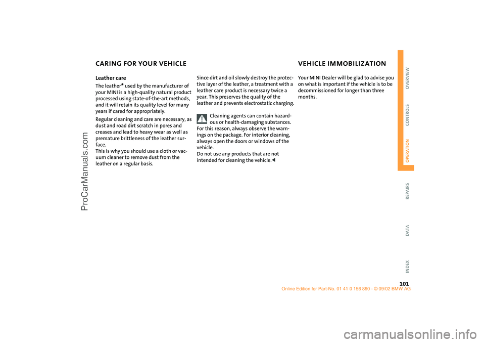
ON-BOARD TOOL KIT WINDSHIELD WIPER BLADESStorage locationThe picture shows as an example tire
change set with on-board tools for vehicles
with the space-saver spare tire.
Depending on the level of equipment
options, your MINI is fitted with a special
on-board tool kit stored at the following
locations:
Tire change set for space-saver spare tire:
In the cargo area under the floor mat.
MINI Mobility System with tire change set
and on-board tools:
In the cargo area under the floor mat.
Tire change set and on-board tools for Run
Flat tires:
Tire change set: in cargo area in a separate
bag – On-board tools: on the left behind
the side panels next to the emergency kit,
see page 124.
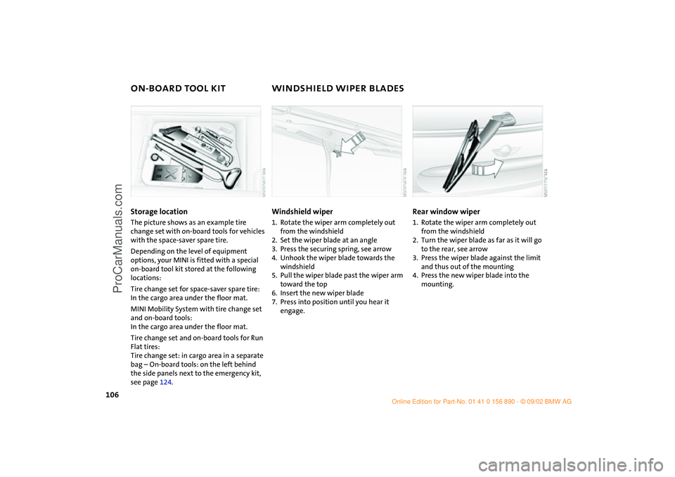
Windshield wiper1. Rotate the wiper arm completely out
from the windshield
2. Set the wiper blade at an angle
3. Press the securing spring, see arrow
4. Unhook the wiper blade towards the
windshield
5. Pull the wiper blade past the wiper arm
toward the top
6. Insert the new wiper blade
7. Press into position until you hear it
engage.
Rear window wiper1. Rotate the wiper arm completely out
from the windshield
2. Turn the wiper blade as far as it will go
to the rear, see arrow
3. Press the wiper blade against the limit
and thus out of the mounting
4. Press the new wiper blade into the
mounting.
ba.book Seite 106 Montag, 5. August 2002 8:09 20
ProCarManuals.com
Page 127 of 148

125
OVERVIEW REPAIRSOPERATION CONTROLS DATA INDEX
JUMP-STARTINGPreparing for jump-starting1. Check whether the battery of the sup-
port vehicle has 12 Volts and approxi-
mately the same capacity – measured in
Ah, printed on the battery
2. Switch off the engine of the support
vehicle
3. Switch off any electrical systems and
components in both vehicles – except
for the hazard warning flashers of the
support vehicle.
>Do not disconnect the discharged bat-
tery from the vehicle electrical system
>Make certain that there is no contact
between the bodywork of the two
vehicles – short circuit hazard!
4. With the battery of the MINI COOPER,
remove the cover panel. To do so, press
both clips at the same time
or
with the MINI COOPER S, open the cover
of the positive terminal connection for
jump-starting
*, see arrow 1.
Connect the jumper cables
Adhere to the sequence also when
providing support for other vehicles;
failure to observe this procedure can lead
to sparks at the terminals and pose an
injury hazard.<
1. On the MINI COOPER S, the positive ter-
minal connection for jump-starting, see
arrow 1, functions as the positive bat-
tery terminal.
Make a connection with the "+" jumper
cable between the positive terminal of
the discharged battery and the positive
terminal of the support battery
2. Use the second, "–" jumper cable to set
up the connection between the negative
terminals of both vehicles.
To do so:
>Connect one terminal clamp to the
negative terminal and/or to an engine
or body ground of the support vehicle
>Connect the second terminal clamp to
the negative terminal of the battery
and/or to an engine or body ground of
the vehicle to be started. For the MINI,
see arrow 2.
Performing the jump-start1. Start the engine of the vehicle providing
the current and allow to run at a fast idle
speed for several minutes
2. Start the engine on the vehicle with the
discharged battery in the usual manner.
>If the first start attempt is not suc-
cessful, wait a few minutes before
another attempt in order to allow the
discharged battery to recharge
On the MINI:
Before disconnecting the jumper
cables, switch on the lighting, rear window
defroster and the highest blower speed as
well as the engine for at least approx.
10 seconds to prevent a voltage surge from
the regulator to the electrical systems and
components.<
3. Then disconnect the jumper cables in
the reverse order.
If necessary have the battery checked and
completely charged at a MINI Dealer.
ba.book Seite 125 Montag, 5. August 2002 8:09 20
ProCarManuals.com
Page 129 of 148
127
OVERVIEW REPAIRSOPERATION CONTROLS DATA INDEX
TOWINGTow-startingIt is not possible to start the engine of a
vehicle equipped with an automatic trans-
mission by towing or pushing.
For instructions on jump starting, refer to
page 124.
Never attempt to use your vehicle to push
another car, since damage to the energy-
absorbing bumpers could result.Towing a vehicle
Only tow vehicles with Continuously
Variable automatic Transmission
(CVT) with the front wheels raised or on a
special transport vehicle, otherwise the
transmission can be damaged.<
1. Place gear selector lever in neutral or idle
2. Towing speed:
Max. 45 mph / 70 km/h
3. Towing distance:
Max. 95 miles / 150 km
4. Leave the ignition key at position 1 to
ensure that the brake lamps, turn sig-
nals, horn and windshield wipers remain
operative, and to prevent the steering
lock detent from engaging
5. Switch on the hazard-warning system,
observe country-specific regulations.
Find some means of identifying the vehicle
in tow, for instance, place a sign or warning
triangle in the rear window.
Make sure that the ignition key
remains in position 1 even when the
electrical system has failed to prevent the
steering lock from engaging.
The steering and brakes are without power
assist when the engine is off. This means
that increased effort is required for steer-
ing and braking.<
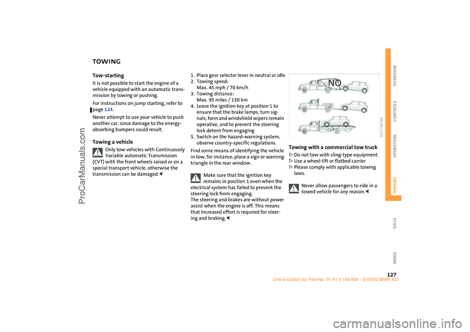
Towing with a commercial tow truck >Do not tow with sling-type equipment
>Use a wheel-lift or flatbed carrier
>Please comply with applicable towing
laws.
Never allow passengers to ride in a
towed vehicle for any reason.<
ba.book Seite 127 Montag, 5. August 2002 8:09 20
ProCarManuals.com
Page 139 of 148
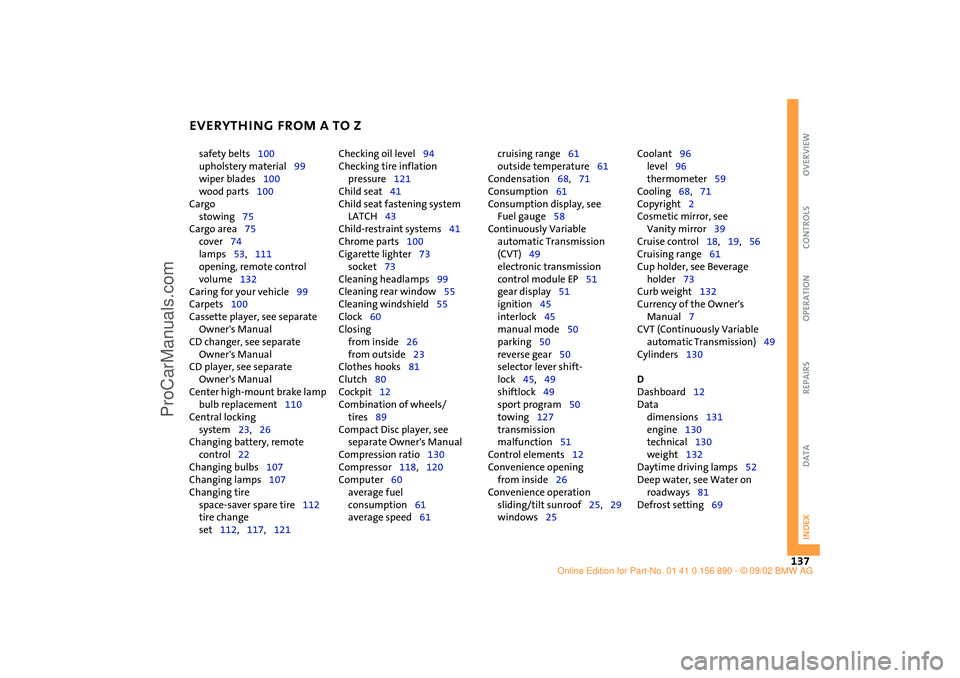
EVERYTHING FROM A TO Z
137
OVERVIEW REPAIRS OPERATION CONTROLS DATA INDEX
safety belts100
upholstery material99
wiper blades100
wood parts100
Cargo
stowing75
Cargo area75
cover74
lamps53,111
opening, remote control
volume132
Caring for your vehicle99
Carpets100
Cassette player, see separate
Owner's Manual
CD changer, see separate
Owner's Manual
CD player, see separate
Owner's Manual
Center high-mount brake lamp
bulb replacement110
Central locking
system23,26
Changing battery, remote
control22
Changing bulbs107
Changing lamps107
Changing tire
space-saver spare tire112
tire change
set112,117,121 Checking oil level94
Checking tire inflation
pressure121
Child seat41
Child seat fastening system
LATCH43
Child-restraint systems41
Chrome parts100
Cigarette lighter73
socket73
Cleaning headlamps99
Cleaning rear window55
Cleaning windshield55
Clock60
Closing
from inside26
from outside23
Clothes hooks81
Clutch80
Cockpit12
Combination of wheels/
tires89
Compact Disc player, see
separate Owner's Manual
Compression ratio130
Compressor118,120
Computer60
average fuel
consumption61
average speed61 cruising range61
outside temperature61
Condensation68,71
Consumption61
Consumption display, see
Fuel gauge58
Continuously Variable
automatic Transmission
(CVT)49
electronic transmission
control module EP51
gear display51
ignition45
interlock45
manual mode50
parking50
reverse gear50
selector lever shift-
lock45,49
shiftlock49
sport program50
towing127
transmission
malfunction51
Control elements12
Convenience opening
from inside26
Convenience operation
sliding/tilt sunroof25,29
windows25 Coolant96
level96
thermometer59
Cooling68,71
Copyright2
Cosmetic mirror, see
Vanity mirror39
Cruise control18,19,56
Cruising range61
Cup holder, see Beverage
holder73
Curb weight132
Currency of the Owner's
Manual7
CVT (Continuously Variable
automatic Transmission)49
Cylinders130
D
Dashboard12
Data
dimensions131
engine130
technical130
weight132
Daytime driving lamps52
Deep water, see Water on
roadways81
Defrost setting69
ba.book Seite 137 Montag, 5. August 2002 8:09 20
ProCarManuals.com
Page 140 of 148

EVERYTHING FROM A TO Z
138
Defrosting windows69,72
air conditioning system69
automatic climate
control72
Dimensions131
Dimming
interior mirror39
Dipstick, engine oil94
Dirt on the paintwork99
Disc brakes84
Displacement130
Display elements13,14
coolant thermometer59
fuel gauge58
indicator and warning
lamps15
odometer58
service interval display60
with navigation system14
Display lighting53
Distance remaining61
Doors
keys22
locking24
manual operation25
unlocking24
DOT quality grades87
Driving lamps52
Driving notes, general81
Dry air68,71 DSC (Dynamic Stability
Control)16,63
Dynamic Stability Control
(DSC)16,63
E
Easy entry35
EBD (Electronic Brake Force
Distribution)16,83
Electric power windows28
Electrical defect
driver's door25
sliding/tilt sunroof30
tailgate27
Electronic Brake Force
Distribution (EBD)16,83
Electronic transmission control
module
Continuously Variable
automatic Transmission
(CVT)51
Emergency operation
driver's door25
sliding/tilt sunroof30
tailgate27
Engine80
electronics17
power output17
speed17,58
starting46 Engine compartment
MINI COOPER92
MINI COOPER S93
Engine oil94
additives95
consumption94
dipstick94
High Performance
Synthetic Oil96
level94
pressure15
recommended grades of
oil95
viscosities96
Entry to the rear35
Exterior finish, care99
Exterior mirrors39
Eyelets, towing126
F
Failure, tires64
False alarm32
Fans68
Fastening safety belts16,38
Filling canister118,119
Filling hose118
First-aid kit124
Flat116 Flat tire64,112
MINI Mobility System118
Run Flat tires116
space-saver spare tire112
Flat Tire Monitor16,17,64
Floor coverings, floor
carpets100
Fluid capacities
fuel tank133
headlamp washer
system133
windshield washer
system133
Fog lamps53
Foldable rear backrest74
"Follow me home" lamps52
Foot mats100
Footbrake84
Footwell lamps53
bulb replacement111
Front airbags40
Front fog lamps
bulb replacement108
Front seat adjustment34
Fuel
consumption61
consumption display58
preparation130
quality83
tank capacity82,133
ba.book Seite 138 Montag, 5. August 2002 8:09 20
ProCarManuals.com
Page 141 of 148
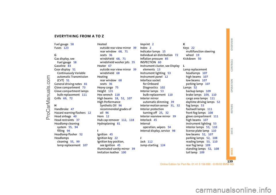
EVERYTHING FROM A TO Z
139
OVERVIEW REPAIRS OPERATION CONTROLS DATA INDEX
Fuel gauge58
Fuses123
G
Gas display, see
Fuel gauge58
Gasoline83
Gear display51
Continuously Variable
automatic Transmission
(CVT)51
General driving notes81
Glove compartment73
Glove compartment lamps
bulb replacement111
Grills69,72
H
Handbrake47
Hazard warning flashers12
Head airbags40
Head restraints37
Headlamp cleaning
system55,94
filling94
Headlamp flasher52
Headlamps
cleaning55,99
lamp replacement107 Heated
outside rear view mirror39
rear window68,71
seats36
windshield68,71
windshield washer jets55
Heater67
outside rear view mirror39
windshield68
Heating
rear window68
seats36
Heavy cargo75
Height131
Hex wrench118
High beams18,52,107
High Performance
Synthetic Oil96
recommended grades of
oil96
Horn12
Hub cap remover112,118
Hydroplaning81
I
Ignition45
Ignition key22
Ignition key position,
see Ignition45
Illuminated vanity mirror39
Imitation leather100 Imprint2
Index2
Indicator lamps15
Individual air distribution72
Inflation pressure85
INSPECTION60
Instrument cluster, see Display
elements13
Instrument lighting53
Instrument panel12
Interface socket
for Onboard
Diagnostics102
Interior lamps53
bulb replacement110
Interior mirror
automatic dimming39
Interior motion sensor31,32
Interior protection
turning off25,32
Interior rearview mirror39
Interlock45
Interval
operation, wipers54
Interval display, service98
J
Jack112
Jump-starting124 K
Keys22
multifunction steering
wheel19
Kickdown50
L
Lamp replacement
headlamps107
high beams107
low beams107
parking lamp107
Lamps52
backup lamps109
brake lamps109,110
cargo area lamps111
daytime driving lamps52
fog lamps53
footwell lamps111
front fog lamps108
glove compartment111
high beams107
instrument lighting53
interior lamps53,110
license plate lamp110
low beams52,107
parking lamps52,108
reading lamps53,110
rear fog lamp109
standing lamps52,108
tail lamp109
ba.book Seite 139 Montag, 5. August 2002 8:09 20
ProCarManuals.com