ESP MINI COOPER 2003 Owners Manual
[x] Cancel search | Manufacturer: MINI, Model Year: 2003, Model line: COOPER, Model: MINI COOPER 2003Pages: 148, PDF Size: 3.17 MB
Page 9 of 148

7
OVERVIEW REPAIRS OPERATION CONTROLS DATA INDEX
Editorial notice
The manufacturer pursues a policy of con-
tinuous, ongoing development that is con-
ceived to ensure that the MINI continues to
embody the highest quality and safety
standards combined with advanced, state-
of-the-art technology. For this reason, the
features described in this Owner's Manual
could differ from those on your vehicle. Nor
can errors and omissions be entirely ruled
out.
You are therefore asked to appreciate that
no claims can be entertained on the basis
of the data, illustrations or descriptions in
this Owner's Manual.
For your own safety
Use unleaded gasoline only. Fuels
containing up to and including 10 %
Ethanol or other oxygenates with up to
2.8 % oxygen by weight – i. e. 15 % MTBE or
3% methanol plus an equivalent amount of
co-solvent – will not void the applicable
warranties with respect to defects in mate-
rials or workmanship. Field experience has
indicated significant differences in fuel
quality – i. e. volatility, composition, addi-
tives, etc. – among gasolines offered for
sale in the United States and Canada. The
use of poor-quality fuels may result in
driveability, starting and stalling problems,
especially under certain environmental
conditions such as high ambient tempera-
ture and high altitude.
Should you encounter driveability prob-
lems which you suspect could be related to
the fuel you are using, we recommend that
you respond by switching to a recognized
high-quality brand.
Failure to comply with these recommenda-
tions may result in unscheduled mainte-
nance.
Obey pertinent safety rules when you are
handling gasoline.
<
Important safety information.
For your own safety, use genuine
parts and accessories approved by the
manufacturer of the MINI.
When you purchase accessories tested
and approved by the manufacturer of the
MINI and Original MINI Parts, you simulta-
neously acquire the assurance that they
have been thoroughly tested by the manu-
facturer of the MINI to ensure optimum
performance when installed on your
vehicle.
The manufacturer of the MINI warrants
these parts to be free from defects in
material and workmanship.
The manufacturer of the MINI will not
accept any liability for damages resulting
from installation of parts and accessories
not approved by the manufacturer of the
MINI.
The manufacturer of the MINI cannot test
every product from other manufacturers to
verify if it can be used on a MINI safely and
without risk to either the vehicle, its opera-
tion, or its occupants.
Original MINI Parts, MINI Accessories and
other products approved by the manufac-
turer of the MINI, together with profes-
sional advice on using these items, are
available from all MINI Dealers.
NOTES
ba.book Seite 7 Montag, 5. August 2002 8:09 20
ProCarManuals.com
Page 17 of 148

15
OVERVIEW REPAIRS OPERATION CONTROLS DATA INDEX
INDICATOR AND WARNING LAMPS
Technology
that monitors itself
The system runs a check on the warning
and indicator lamps marked by
●
each time
you switch on the ignition. They each light
up once for different periods of time.
If a malfunction should occur in one of
these systems, the corresponding lamp
does not go out after the engine is started
or it lights up while the vehicle is moving.
You will see below the correct way to react
to this.
Red: stop immediately
Battery charge current
●
The battery is no longer being
charged. Indicates a defective alter-
nator drive belt or a problem with the
charge circuit. Please contact the nearest
MINI Dealer.
If this lamp lights up, the power-assist for
steering can be deactivated.
If the drive belt is defective, do not
continue driving. The engine could be
damaged due to overheating. When the
power-assist is deactivated, increased
steering effort is required.
<
Engine oil pressure
●
Stop immediately. Switch off
engine. Check the engine oil and fill
as needed. Please contact the nearest MINI
Dealer.
Do not continue driving, otherwise,
the engine could be damaged
because of inadequate lubrication.
<
Brake warning lamp
●
If the lamp comes on when the
parking brake is not engaged:
Check the brake fluid level. Before driving
further, be sure to comply with the infor-
mation on pages 84 and 97.
Brake warning lamp for Canadian
models.
With navigation system option:
Coolant temperature warning
lamp in the speedometer
●
Lights up while driving:
Engine is too hot. Switch off the engine
immediately and allow to cool down, see
also page 59.
ba.book Seite 15 Montag, 5. August 2002 8:09 20
ProCarManuals.com
Page 19 of 148

17
OVERVIEW REPAIRS OPERATION CONTROLS DATA INDEX
INDICATOR AND WARNING LAMPS
Yellow: check as soon as possible
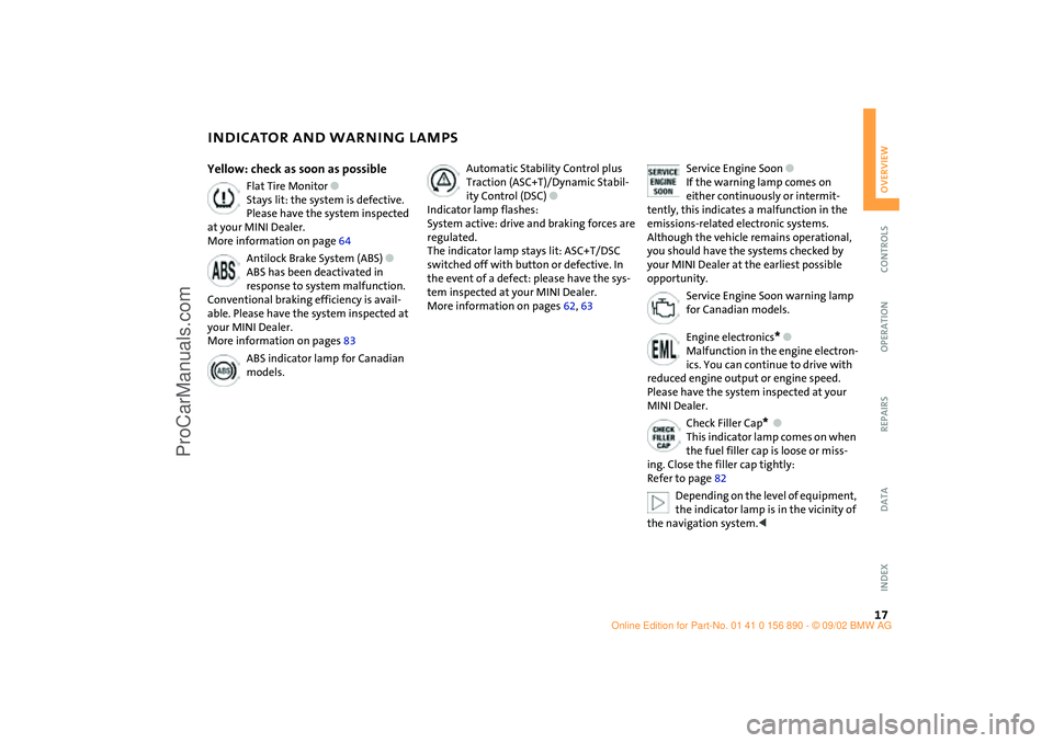
Flat Tire Monitor
●
Stays lit: the system is defective.
Please have the system inspected
at your MINI Dealer.
More information on page 64
Antilock Brake System (ABS)
●
ABS has been deactivated in
response to system malfunction.
Conventional braking efficiency is avail-
able. Please have the system inspected at
your MINI Dealer.
More information on pages 83
ABS indicator lamp for Canadian
models.
Automatic Stability Control plus
Traction (ASC+T)/Dynamic Stabil-
ity Control (DSC)
●
Indicator lamp flashes:
System active: drive and braking forces are
regulated.
The indicator lamp stays lit: ASC+T/DSC
switched off with button or defective. In
the event of a defect: please have the sys-
tem inspected at your MINI Dealer.
More information on pages 62, 63
Service Engine Soon
●
If the warning lamp comes on
either continuously or intermit-
tently, this indicates a malfunction in the
emissions-related electronic systems.
Although the vehicle remains operational,
you should have the systems checked by
your MINI Dealer at the earliest possible
opportunity.
Service Engine Soon warning lamp
for Canadian models.
Engine electronics
*
●
Malfunction in the engine electron-
ics. You can continue to drive with
reduced engine output or engine speed.
Please have the system inspected at your
MINI Dealer.
Check Filler Cap
*
●
This indicator lamp comes on when
the fuel filler cap is loose or miss-
ing. Close the filler cap tightly:
Refer to page 82
Depending on the level of equipment,
the indicator lamp is in the vicinity of
the navigation system.
<
ba.book Seite 17 Montag, 5. August 2002 8:09 20
ProCarManuals.com
Page 36 of 148

34
SEAT ADJUSTMENTImportant adjustment information
Never try to adjust your seat while
operating the vehicle. The seat could
respond with an unexpected movement,
and the ensuing loss of vehicle control
could lead to an accident.
Never ride with the backrest reclined to an
extreme horizontal angle – especially
important for front passengers to remem-
ber. Keep the backrest relatively upright to
minimize the risk of sliding under the
safety belt and sustaining injury in an acci-
dent.<
To adjust the seats, see the following sec-
tion.
Longitudinal seat adjustment 1. Lift the handle
2. Push the seat into the desired position
3. After releasing the handle, apply pres-
sure to the seat to ensure that the latch
engages securely.
Make corrections in the longitudinal
adjustment of the seat to ensure that
the safety belt still fits firmly against your
body. If you do not do this, the protection
provided by the safety belt may be
reduced.<
Seat height 1. To raise:
Pull the handle up repeatedly, continu-
ing until the seat reaches the desired
height
2. To lower:
Push the handle repeatedly, continuing
until the seat reaches the desired height.
ba.book Seite 34 Montag, 5. August 2002 8:09 20
ProCarManuals.com
Page 42 of 148

40
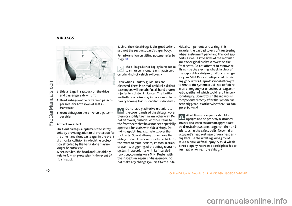
AIRBAGS 1Side airbags in seatback on the driver
and passenger side – front
2Head airbags on the driver and passen-
ger sides for both rows of seats –
front/rear
3Front airbags on the driver and passen-
ger sidesProtective effectThe front airbags supplement the safety
belts by providing additional protection for
the driver and front passenger in the event
of a frontal collision in which the protec-
tion afforded by the belts alone may no
longer be sufficient.
When needed, the head and side airbags
help to furnish protection in the event of
side impact.
Each of the side airbags is designed to help
support the seat occupant's upper body.
For information on sitting posture, refer to
page 33.
The airbags do not deploy in response
to minor collisions, rear impacts and
certain kinds of vehicle rollover.<
Even when all safety guidelines are
observed, there is a small residual risk that
passengers will sustain facial, hand or arm
injuries in isolated instances. The ignition
and inflation noise may induce a mild tem-
porary hearing loss in sensitive individuals.
Do not apply adhesive materials to
the cover panels of the airbags, cover
them or modify them in any other way. Do
not fit covers, cushions or other items to
the front seats that have not been specially
approved for seats with side airbags. Do
not hang clothing, e. g. jackets, over the
backrests. Do not attempt to remove the
airbag restraint system from the vehicle. In
the event of malfunctions, immobilization
or use, i. e. triggering, of the airbag restraint
system in accordance with its intended
function, commission a MINI Dealer with
the inspection, repair or disassembly. Do
not make any changes yourself to the indi-
vidual components and wiring. This
includes the padded covers of the steering
wheel, instrument panel and the roof sup-
ports, as well as the sides of the roofliner
and the original backrest covers on the
front seats. Do not attempt to remove or
dismantle the steering wheel. In view of
the applicable safety regulations, arrange
for your MINI Dealer to dispose of the air-
bag generators. Unprofessional attempts
to service the system could lead to failure
in an emergency or undesired airbag acti-
vation, either of which could result in per-
sonal injury. Do not touch the individual
components directly after the system has
been triggered, as otherwise there is a dan-
ger of burns.<
At all times, occupants should sit
upright and be properly restrained,
infants and small children in appropriate
child-restraint systems, larger children and
adults using the safety belts. Never let an
occupant's head rest near or on a head air-
bag because the inflating airbag could
cause serious or fatal injury. A child which
is not properly restrained could place his or
her head on or near the airbag.<
ba.book Seite 40 Montag, 5. August 2002 8:09 20
ProCarManuals.com
Page 43 of 148

41
OVERVIEW REPAIRS OPERATIONCONTROLS DATA INDEX
AIRBAGS TRANSPORTING CHILDREN SAFELYIndicator lamp
The indicator lamp on the instru-
ment panel shows the airbag sys-
tem status starting from ignition
key position 1.
System operational:
>The indicator lamp comes on briefly.
System malfunction:
>The indicator lamp does not come on
>The indicator lamp fails to go out after
the engine has been started, or it comes
on during normal driving.
A system defect could prevent the airbags
from deploying in response to a severe
impact occurring within the system's nor-
mal triggering range.
Have the airbag system checked as soon as
possible by your MINI Dealer.
Children younger than 12 years of age or
smaller than 5 ft / 150 cm must be trans-
ported in suitable child-restraint system.
Otherwise there is an increased risk of
injury in the event of an accident.
Commercially-available child-restraint sys-
tems are designed to be secured with a lap
belt or with the lap belt portion of a combi-
nation lap/shoulder belt. Improperly or
inadequately installed restraint systems
can increase the risk of injury to children.
Always read and follow the instructions
that come with the system.
If you use a child-restraint system with a
tether strap:
Your vehicle has one of two different types
of child-restraint anchor fittings on the
back of the rear seats, see arrows 1 or 2.
Depending on the location selected for
seating in the rear passenger area, attach
the tether strap to the corresponding
anchorage point to secure the child-
restraint system.
Adjust the tether strap according to the
child-restraint manufacturer's instructions.
Anchor fitting 1 is shown above.
Anchor fitting 2 is shown in the next
column.<
ba.book Seite 41 Montag, 5. August 2002 8:09 20
ProCarManuals.com
Page 64 of 148

62
AUTOMATIC STABILITY CONTROL PLUS TRACTION (ASC+T)
*
The concept
This system optimizes vehicle stability and
traction, especially when just starting off,
when accelerating or when cornering.
ASC+T recognizes the danger present in
traction loss and will increase driving sta-
bility and traction by reducing the engine's
output and, if necessary, by applying the
brakes to the front wheels. ASC+T is opera-
tional each time you start the engine.
The laws of physics cannot be
repealed, even with ASC+T. An appro-
priate driving style always remains the
responsibility of the driver. Avoid using the
additional safety margin provided by the
system as an excuse for taking unnecessary
risks.
Do not make any modifications to the
ASC+T system. Allow only authorized tech-
nicians to perform service procedures on
the ASC+T.<
Indicator lamp
The indicator lamp on the instru-
ment cluster will go out shortly
after the ignition has been
switched on, see pages 16, 17.
If the indicator lamp flashes:
ASC+T controls the drive and braking
forces.
If the indicator lamp fails to go out
after the engine is started, or if it
comes on during normal driving and stays
on:
The system is defective or was turned off
using the button.
The described stabilizing operations are no
longer available.
You can, however, drive the vehicle nor-
mally without ASC+T.
In the event of a malfunction, please see
your MINI Dealer, see pages 16, 17.<
Switch off the ASC+TBriefly press the switch.
The indicator lamp stays lit.
When driving with snow chains or to "rock
free" in snow, it can be helpful to switch off
the ASC+T for a brief period.
To maintain vehicle stability, always
drive with the ASC+T switched on
whenever possible.
ba.book Seite 62 Montag, 5. August 2002 8:09 20
ProCarManuals.com
Page 65 of 148

63
OVERVIEW REPAIRS OPERATIONCONTROLS DATA INDEX
DYNAMIC STABILITY CONTROL (DSC)
*
The concept
This system maintains driving stability
even in critical driving situations.
The system optimizes vehicle stability dur-
ing acceleration and when starting from a
full stop, as well as optimizing traction. In
addition, it recognizes unstable vehicle
conditions, such as understeering or over-
steering, and, as far as is possible within
the laws of physics, helps keep the vehicle
on a steady course by reducing the rpms
and by brake applications to the individual
wheels.
The DSC is operational every time you start
the engine. DSC contains the functions
Antilock Brake System (ABS), Electronic
Brake Force Distribution (EBD), and ASC+T.
The laws of physics cannot be
repealed, even with DSC. An appro-
priate driving style always remains the
responsibility of the driver. We therefore
urge you to avoid using the additional
safety margin of the system as an excuse
for taking risks.
Do not make any modifications to the DSC
system. Allow only authorized technicians
to perform service procedures on the
DSC.<
Indicator lamp
The indicator lamp on the instru-
ment cluster will go out shortly
after the ignition has been
switched on, see pages 16, 17.
If the indicator lamp flashes:
DSC controls the drive and braking forces.
If the indicator lamp fails to go out
after the engine is started, or if it
comes on during normal driving and stays
on:
The system is defective or was turned off
using the button.
The described stabilizing operations are no
longer available.
The vehicle will remain completely opera-
tional, however, without DSC.
In the event of a malfunction, please see
your MINI Dealer, see pages 16, 17.<
To switch off the DSCBriefly press the switch.
The indicator lamp stays lit.
When driving with snow chains, it may be
effective to switch off the DSC for a brief
period.
To maintain stability, always drive
with the DSC switched on whenever
possible.
ba.book Seite 63 Montag, 5. August 2002 8:09 20
ProCarManuals.com
Page 68 of 148

66
PARK DISTANCE CONTROL (PDC)*The conceptThe PDC assists you when you back into a
parking space. A signal tone tells you the
current distance to an object behind your
vehicle. To do this, four ultrasonic sensors
in the rear bumper measure the distance to
the nearest object.
The sensors on each side have a range of
approx. 2 ft / 60 cm, the middle sensors
one of approx. 5 ft / 1.5 m.
The system starts to operate automatically
about one second after you select reverse
with the ignition key in position 2.
Wait for this one second before you
drive backwards.<
PDC is deactivated when you shift away
from Reverse.
You can have a signal tone set by your
MINI Dealer as a confirmation that
PDC has been activated.<
Acoustical signalsThe distance to an object is indicated by a
tone sounding at intervals. As the distance
between vehicle and object decreases, the
intervals between the tones become
shorter. A continuous tone indicates the
presence of an object less than 8 in / 20 cm
away.
The warning signal is canceled after
approx. three seconds if the distance to the
object remains constant during this time,
for instance if you are moving parallel to a
wall.
System malfunctions will be indicated by a
continuous high-pitched tone when the
system is activated the first time. Please
have your MINI Dealer resolve the problem.Volume controlThe volume of the Park Distance Control
signal can be adjusted from level 1 – soft –
to level 6 – loud.
The volume can be set by your MINI
Dealer.<
Even with PDC, final responsibility for
estimating the distance between the
vehicle and any objects always remains
with the driver.
Even when sensors are involved, there is a
blind spot in which objects cannot be de-
tected. Recognition of some objects can be
beyond the limits of physical ultrasonic
measurement, for example with towing
bars or hitches or with thin or wedge-
shaped objects. Moreover, low objects that
have already been detected – such as a curb
edge – can disappear out of the range of
the sensors before a continuous tone
sounds.
Loud sources of sound outside and inside
your vehicle can drown the PDC signal
tone.<
Keep the sensors clean and free of ice
or snow in order to ensure that they
will continue to operate effectively.
Do not apply high pressure spray to the
sensors for a prolonged period of time.
Always maintain a distance which is
greater than 4 in / 10 cm.<
ba.book Seite 66 Montag, 5. August 2002 8:09 20
ProCarManuals.com
Page 87 of 148

85
OVERVIEW REPAIRSOPERATIONCONTROLS DATA INDEX
TIRE INFLATION PRESSUREInformation for your safetyThe factory-approved radial tires are
matched to the vehicle and have been
selected to provide optimum safety and
driving comfort if used properly.
It is not merely the tire's service life, but
also driving comfort and – above all else –
driving safety that depend on the condition
of the tires and the maintenance of the
specified tire pressure.
Incorrect inflation pressure is a frequent
cause of tire damage. It also significantly
influences the roadholding ability of your
MINI.
Check tire inflation pressures regu-
larly – at least every two weeks and
before beginning a longer trip. Failure to
observe these precautions can result in
incorrect tire pressures, which cause unsta-
ble handling response as well as tire dam-
age, and can ultimately lead to an accident.
Also check the inflation pressure on the
space-saver spare tire.
turer of your MINI, which can be asked for
from your MINI Dealer.
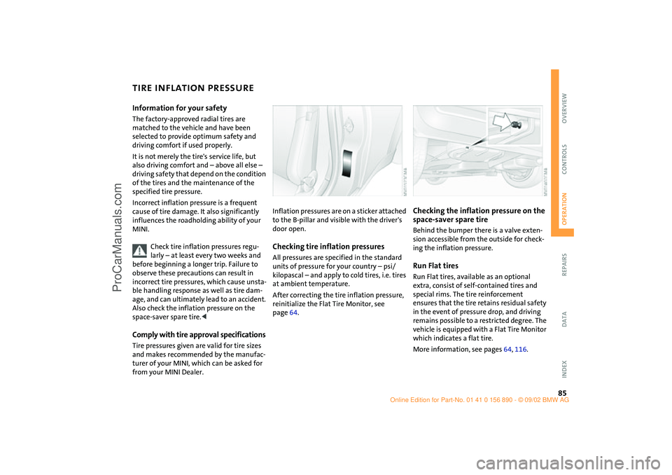
Inflation pressures are on a sticker attached
to the B-pillar and visible with the driver's
door open.Checking tire inflation pressuresAll pressures are specified in the standard
units of pressure for your country – psi/
kilopascal – and apply to cold tires, i.e. tires
at ambient temperature.
After correcting the tire inflation pressure,
reinitialize the Flat Tire Monitor, see
page 64.
Checking the inflation pressure on the
space-saver spare tireBehind the bumper there is a valve exten-
sion accessible from the outside for check-
ing the inflation pressure.Run Flat tiresRun Flat tires, available as an optional
extra, consist of self-contained tires and
special rims. The tire reinforcement
ensures that the tire retains residual safety
in the event of pressure drop, and driving
remains possible to a restricted degree. The
vehicle is equipped with a Flat Tire Monitor
which indicates a flat tire.
More information, see pages 64, 116.
ba.book Seite 85 Montag, 5. August 2002 8:09 20
ProCarManuals.com