service indicator MINI COOPER 2004 Owners Manual
[x] Cancel search | Manufacturer: MINI, Model Year: 2004, Model line: COOPER, Model: MINI COOPER 2004Pages: 152, PDF Size: 1.53 MB
Page 4 of 152

CONTENTS
2
© 2003 Bayerische Motoren Werke
Aktiengesellschaft
Munich, Germany
Reprinting, including excerpts, only with the
written consent of BMW AG, Munich.
Order No. 01 41 0 157 644
US English VIII/03
Printed in Germany
Printed on environmentally friendly paper,
bleached without chlorine, suitable for recycling.
NOTES
About this Owner's Manual6
Symbols used6
Your individual vehicle6
Editorial notice7
For your own safety7
Symbol on vehicle parts8
Service and warranty8
Reporting safety defects9
OVERVIEW
Cockpit12
Display elements13
Display elements with navigation
system14
Indicator and warning lamps15
Multifunction steering wheels18
CONTROLS
Opening and closing:
Keys22
Central locking system23
Opening and closing: from outside23
Opening and closing: from inside26
Tailgate27
Electric power windows28
Glass sunroof, electric29
Roller sun blind30
Adjustments:
Safe seating position31
Seat adjustment32
Head restraints33
Entry to the rear34
Safety belts35
Seat heating35
Steering wheel36
Mirrors36
Vehicle Memory37
Transporting children safely38
ProCarManuals.com
Page 5 of 152

3
OVERVIEW REPAIRS OPERATION CONTROLS DATA INDEX
Driving:
Ignition lock41
Starting the engine41
Switching off the engine43
Parking brake43
Manual transmission44
Continuously Variable automatic
Transmission (CVT)45
Parking lamps/Low beams48
Turn signal indicator/Headlamp
flasher49
Instrument lighting49
Fog lamps49
Interior lamps50
Washer/wiper system50
Cruise control52
Everything under control:
Odometer54
Tachometer54
Fuel gauge54
Coolant temperature gauge55
Service interval display56
Clock56
Onboard computer57
Technology for safety and driving
convenience:
All Season traction Control (ASC)59
Dynamic Stability Control (DSC)60
Antilock Brake System (ABS)61
Flat Tire Monitor62
Park Distance Control (PDC)64
Airbags65
Controlling the climate for pleasant
driving:
Air conditioning system67
Automatic climate control70
Interior conveniences:
Glove compartment73
Ashtray, beverage holders74
Cigarette lighter, 12 V power supply74
Loading and transporting cargo:
Cargo area75
Loading cargo76
Roof-mounted luggage rack78
OPERATION, CARE, MAINTENANCE
Special operating instructions:
Break-in procedures82
General driving notes83
Refueling84
Fuel specifications85
Brake system86
Wheels and tires:
Tire inflation pressure87
Tire coding89
Tire condition91
Wheel and tire replacement92
Run Flat tires93
Snow chains94
ProCarManuals.com
Page 15 of 152

13
OVERVIEW REPAIRS OPERATION CONTROLS DATA INDEX
DISPLAY ELEMENTS
1Tachometer54
with indicator and warning lamps,
page 15 ff
2Display for onboard computer57
If there is no onboard computer:
Display of outside temperature and cur-
rent vehicle speed
3Speedometer with indicator and warning
lamps, page 15 ff4Indicator for
>
Odometer54
>
Trip odometer54
>
Service interval56
>
Program display for Continuously Vari-
able automatic Transmission
(CVT)47
5Trip odometer, reset to zero546Fuel gauge54
7Engine coolant temperature gauge55
ProCarManuals.com
Page 16 of 152

14
DISPLAY ELEMENTS WITH NAVIGATION SYSTEM
*
1Tachometer54
with indicator and warning lamps,
page 15 ff
2Additional indicator and warning lamps,
page 16 ff, display for onboard computer
in navigation system, refer to separate
Owner's Manual 3Speedometer with indicator and warning
lamps, page 15 ff
4Trip odometer, reset to zero545Indicator for
>
Odometer54
>
Trip odometer54
>
Service interval56
>
Program display for Continuously Vari-
able automatic Transmission
(CVT)47
ProCarManuals.com
Page 19 of 152

17
OVERVIEW REPAIRS OPERATION CONTROLS DATA INDEX
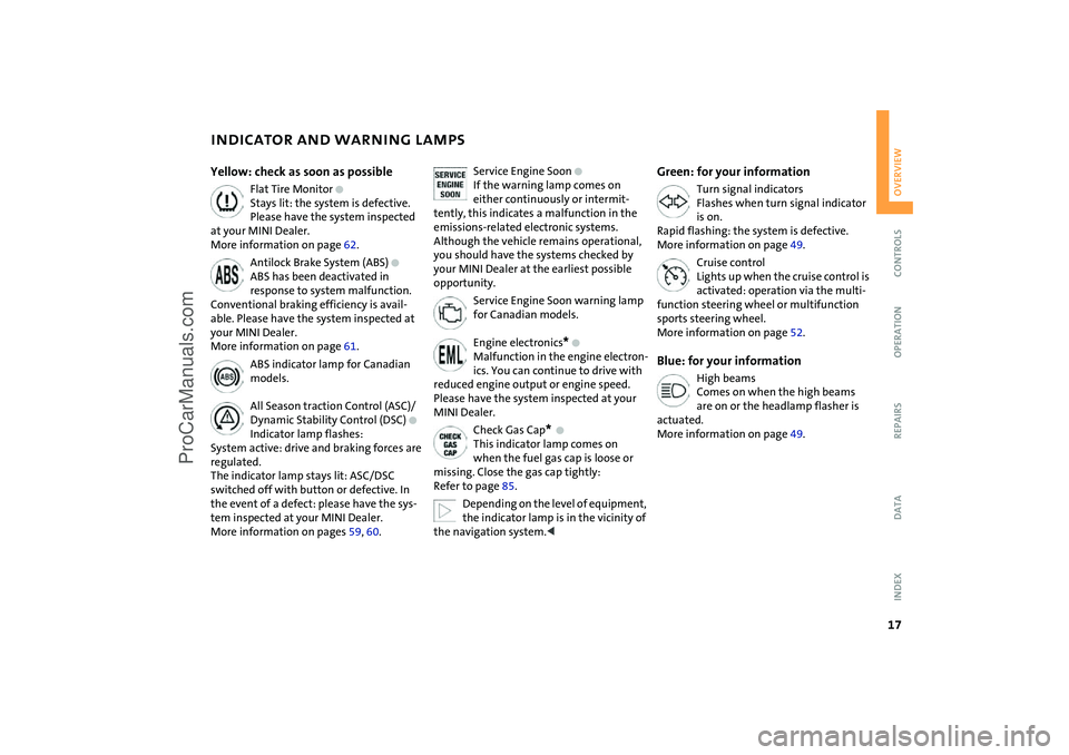
INDICATOR AND WARNING LAMPS
Yellow: check as soon as possible
Flat Tire Monitor
+
Stays lit: the system is defective.
Please have the system inspected
at your MINI Dealer.
More information on page 62.
Antilock Brake System (ABS)
+
ABS has been deactivated in
response to system malfunction.
Conventional braking efficiency is avail-
able. Please have the system inspected at
your MINI Dealer.
More information on page 61.
ABS indicator lamp for Canadian
models.
All Season traction Control (ASC)/
Dynamic Stability Control (DSC)
+
Indicator lamp flashes:
System active: drive and braking forces are
regulated.
The indicator lamp stays lit: ASC/DSC
switched off with button or defective. In
the event of a defect: please have the sys-
tem inspected at your MINI Dealer.
More information on pages 59, 60.
Service Engine Soon
+
If the warning lamp comes on
either continuously or intermit-
tently, this indicates a malfunction in the
emissions-related electronic systems.
Although the vehicle remains operational,
you should have the systems checked by
your MINI Dealer at the earliest possible
opportunity.
Service Engine Soon warning lamp
for Canadian models.
Engine electronics
*
+
Malfunction in the engine electron-
ics. You can continue to drive with
reduced engine output or engine speed.
Please have the system inspected at your
MINI Dealer.
Check Gas Cap
*
+
This indicator lamp comes on
when the fuel gas cap is loose or
missing. Close the gas cap tightly:
Refer to page 85.
Depending on the level of equipment,
the indicator lamp is in the vicinity of
the navigation system.
<
Green: for your information
Turn signal indicators
Flashes when turn signal indicator
is on.
Rapid flashing: the system is defective.
More information on page 49.
Cruise control
Lights up when the cruise control is
activated: operation via the multi-
function steering wheel or multifunction
sports steering wheel.
More information on page 52.
Blue: for your information
High beams
Comes on when the high beams
are on or the headlamp flasher is
actuated.
More information on page 49.
ProCarManuals.com
Page 61 of 152

59
OVERVIEW REPAIRS OPERATIONCONTROLS DATA INDEX
ALL SEASON TRACTION CONTROL (ASC)
*
The concept
This system optimizes driving stability and
traction, especially when just starting off,
when accelerating or when cornering.
ASC recognizes the danger present in trac-
tion loss and will increase driving stability
and traction by reducing the engine's out-
put and, if necessary, by applying the
brakes to the front wheels.
ASC is operational each time you start the
engine. It contains the following functions:
>Antilock Brake System (ABS)
>Cornering Brake Control (CBC)
>Electronic Brake Force Distribution (EBD).
The laws of physics cannot be
repealed, even with ASC. An appropri-
ate driving style always remains the
responsibility of the driver. Avoid using the
additional safety margin provided by the
system as an excuse for taking unnecessary
risks.
Do not make any modifications to the ASC
system. Allow only authorized technicians
to perform service procedures on the
ASC.<
Indicator lamp
The indicator lamp in the display
elements will go out shortly after
the ignition has been switched on,
refer to pages 16, 17.
If the indicator lamp flashes:
ASC controls the drive and braking forces.
If the indicator lamp fails to go out after
the engine is started, or if it comes on dur-
ing normal driving and stays on:
The system is defective or was turned off
using the button.
The described stabilizing operations are no
longer available.
You can, however, drive the vehicle nor-
mally without ASC.
In the event of a malfunction, please see
your MINI Dealer, refer to pages 16, 17.
To switch off the ASCBriefly press the switch.
The indicator lamp stays lit.
When driving with snow chains or to 'rock
free' in snow, it can be helpful to switch off
the ASC for a brief period.
To maintain vehicle stability, always
drive with the ASC switched on
whenever possible.
ProCarManuals.com
Page 62 of 152

60
DYNAMIC STABILITY CONTROL (DSC)
*
The concept
This system optimizes driving stability and
traction, especially when just starting off,
when accelerating or when cornering. It
also maintains driving stability even in criti-
cal driving situations.
DSC recognizes unstable vehicle conditions,
such as understeering or oversteering, and,
as far as is possible within the laws of phys-
ics, helps keep the vehicle on a steady
course by reducing the rpms and by brake
applications to the individual wheels.
The DSC is operational every time you start
the engine. It contains the following func-
tions:
>All Season traction Control (ASC)
>Antilock Brake System (ABS)
>Cornering Brake Control (CBC)
>Electronic Brake Force Distribution (EBD).
The laws of physics cannot be
repealed, even with DSC. An appropri-
ate driving style always remains the respon-
sibility of the driver. Avoid using the addi-
tional safety margin provided by the system
as an excuse for taking unnecessary risks.
Do not make any modifications to the DSC
system. Allow only authorized technicians to
perform service procedures on the DSC.<
Indicator lamp
The indicator lamp in the display
elements will go out shortly after
the ignition has been switched on,
refer to pages 16, 17.
If the indicator lamp flashes:
DSC controls the drive and braking forces.
If the indicator lamp fails to go out after
the engine is started, or if it comes on dur-
ing normal driving and stays on:
The system is defective or was turned off
using the button.
The described stabilizing operations are no
longer available.
The vehicle will remain completely opera-
tional, however, without DSC.
In the event of a malfunction, please see
your MINI Dealer, refer to pages 16, 17.
To switch off the DSCBriefly press the switch.
The indicator lamp stays lit.
When driving with snow chains, it may be
effective to switch off the DSC for a brief
period.
To maintain stability, always drive
with the DSC switched on whenever
possible.
ProCarManuals.com
Page 67 of 152

65
OVERVIEW REPAIRS OPERATIONCONTROLS DATA INDEX
AIRBAGS1Side airbags in seatback on the driver
and passenger side: front
2Head airbags on the driver and passenger
sides for both rows of seats: front/rear
3Front airbags on the driver and passen-
ger sidesProtective effectThe front airbags supplement the safety belts
by providing additional protection for the
driver and front passenger in the event of a
frontal collision in which the protection
afforded by the belts alone may no longer be
sufficient.
When needed, the head and side airbags help
to furnish protection in the event of side
impact.
Each of the side airbags is designed to help
support the seat occupant's upper body.
The airbags are designed to not be trig-
gered in certain types of collisions, e.g. in
minor accidents, certain kinds of vehicle
rollover and rear impact.
For information on the ideal seating position,
refer to page 31.
Do not apply adhesive materials to the
cover panels of the airbags, cover them
or modify them in any other way. Do not fit
covers, cushions or other items to the front
seats that have not been specially approved
for seats with side airbags. Do not hang cloth-
ing, e. g. jackets, over the backrests.
Do not attempt to remove the airbag
restraint system from the vehicle. Do not
make any changes yourself to the individual
components and wiring. This includes the
padded covers of the steering wheel, instru-
ment panel and roof supports, as well as the
sides of the roofliner and the original back-
rest covers on the front seats. Do not attempt
to remove or dismantle the steering wheel.
Do not touch the individual components
directly after the system has been triggered,
as otherwise there is a danger of burns. In the
event of malfunctions, immobilization or use,
i.e. triggering, of the airbag restraint system
in accordance with its intended function,
please commission a MINI Dealer with the
inspection, repair or disassembly. Unprofes-
sional attempts to service the system could
lead to failure in an emergency or undesired
airbag activation, either of which could result
in personal injury. In view of the applicable
safety regulations, please arrange for your
MINI Dealer to dispose of the airbag genera-
tors.<
Airbag warning information is also pro-
vided on the sun visors.Indicator lamp
The indicator lamp in the display
elements shows the status of the
entire airbag system and the seat
belt tensioners starting from ignition key
position 1.
System operational:
>The indicator lamp comes on briefly.
System malfunction:
>The indicator lamp does not come on
starting from ignition key position 1
>The indicator lamp stays lit
>The indicator lamp lights up while driving.
ProCarManuals.com
Page 108 of 152

106
OBD SOCKETThe Onboard Diagnostic OBD interface
socket is located on the left of the driver's
side under the instrument panel and under
a cover.
The cover has the letters OBD on it.
The purpose of the OBD system is to ensure
proper operation of the emission control
system for the vehicle's lifetime. The sys-
tem monitors emission-related compo-
nents for deterioration and malfunction.
An illuminated lamp informs you of
the need for service, not of the
need to stop the vehicle.
However, the system should be checked by
your MINI Dealer at the earliest possible
opportunity.
Indicator lamp for Canadian mod-
els.
Under certain conditions, the indicator will
blink or flash. This indicates a rather severe
level of engine misfire. When this occurs,
you should reduce speed and consult the
nearest MINI Dealer as soon as possible.
Severe engine misfire over only a short
period of time can seriously damage emis-
sion control components, especially the
catalytic converter.
When the gas cap is not properly
tightened, the OBD system can detect
the vapor leak and the indicator will light
up. If the cap is subsequently tightened, the
indicator lamp should go out within a few
days.<
ProCarManuals.com
Page 114 of 152

112
LAMPS AND BULBS1Low beamsH7 bulb, 55 Watts2High beams H7 bulb, 55 Watts
The H7 bulb is pressurized. Therefore,
wear safety glasses and protective
gloves. If the lamp is damaged there is a
risk of injury.
1. Pull on the tab of the cover of the defec-
tive lamp and open it
2. Press the retaining wire lightly at the
eyelet and at the same time guide it out-
wards
3. Fold the retaining wire down
4. Remove the lamp holder and replace the
lamp
5. Reinsert the lamp holder in the correct
position
6. Fold the retaining wire back up and
catch in place.
Ensure that it is placed in the middle of
the wire connector.Xenon lamps* The service life of these bulbs is very long
and the probability of a failure is very low,
provided that they are not switched on and
off an unusual number of times. If one of
these bulbs should nevertheless fail, it is
possible to continue driving with great cau-
tion using the fog lamps, provided traffic
laws in your area do not prohibit this.
Because of the extremely high volt-
ages involved, any work on the xenon
lighting system should be carried out by
technically qualified personnel only. Other-
wise, there is a risk of fatal injury.<
Turn signal indicators, front 21 Watt bulb
1. Open the bonnet
2. Reach into the opening for the turn sig-
nal indicators from above
3. Apply gentle pressure to the bulb holder
while turning it to the left
4. Remove and replace the bulb.Parking lamps and standing lamps 5 Watt bulb
The parking lamps and standing lamps are
integrated in the lamp housing of the turn
signal indicator.
1. Turn the bulb holder to the left and pull
out
2. Remove and replace the bulb.
ProCarManuals.com