display MINI COOPER 2014 Owner's Manual
[x] Cancel search | Manufacturer: MINI, Model Year: 2014, Model line: COOPER, Model: MINI COOPER 2014Pages: 230, PDF Size: 11.58 MB
Page 62 of 230
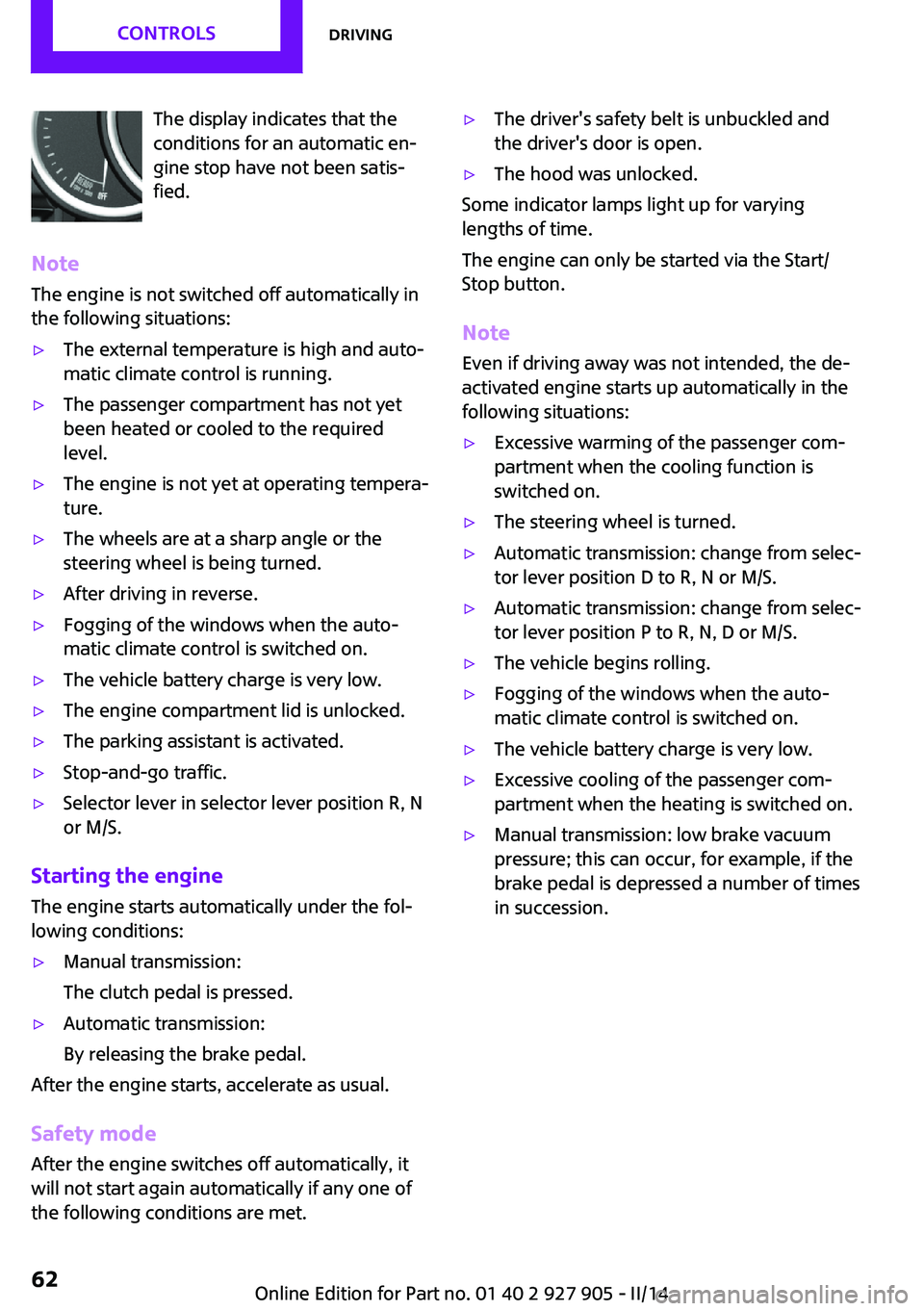
The display indicates that the
conditions for an automatic en‐
gine stop have not been satis‐
fied.
Note
The engine is not switched off automatically in
the following situations:▷The external temperature is high and auto‐
matic climate control is running.▷The passenger compartment has not yet
been heated or cooled to the required
level.▷The engine is not yet at operating tempera‐
ture.▷The wheels are at a sharp angle or the
steering wheel is being turned.▷After driving in reverse.▷Fogging of the windows when the auto‐
matic climate control is switched on.▷The vehicle battery charge is very low.▷The engine compartment lid is unlocked.▷The parking assistant is activated.▷Stop-and-go traffic.▷Selector lever in selector lever position R, N
or M/S.
Starting the engine
The engine starts automatically under the fol‐
lowing conditions:
▷Manual transmission:
The clutch pedal is pressed.▷Automatic transmission:
By releasing the brake pedal.
After the engine starts, accelerate as usual.
Safety mode
After the engine switches off automatically, it
will not start again automatically if any one of
the following conditions are met.
▷The driver's safety belt is unbuckled and
the driver's door is open.▷The hood was unlocked.
Some indicator lamps light up for varying
lengths of time.
The engine can only be started via the Start/
Stop button.
Note
Even if driving away was not intended, the de‐
activated engine starts up automatically in the
following situations:
▷Excessive warming of the passenger com‐
partment when the cooling function is
switched on.▷The steering wheel is turned.▷Automatic transmission: change from selec‐
tor lever position D to R, N or M/S.▷Automatic transmission: change from selec‐
tor lever position P to R, N, D or M/S.▷The vehicle begins rolling.▷Fogging of the windows when the auto‐
matic climate control is switched on.▷The vehicle battery charge is very low.▷Excessive cooling of the passenger com‐
partment when the heating is switched on.▷Manual transmission: low brake vacuum
pressure; this can occur, for example, if the
brake pedal is depressed a number of times
in succession.Seite 62CONTROLSDriving62
Online Edition for Part no. 01 40 2 927 905 - II/14
Page 63 of 230
Activating/deactivating the system
manually
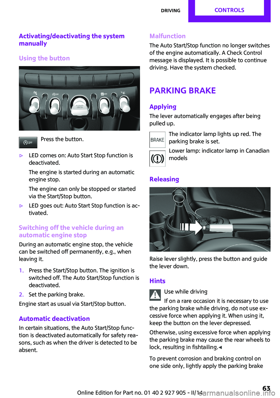
Using the button
Press the button.
▷LED comes on: Auto Start Stop function is
deactivated.
The engine is started during an automatic
engine stop.
The engine can only be stopped or started
via the Start/Stop button.▷LED goes out: Auto Start Stop function is ac‐
tivated.
Switching off the vehicle during an automatic engine stop
During an automatic engine stop, the vehicle
can be switched off permanently, e.g., when
leaving it.
1.Press the Start/Stop button. The ignition is
switched off. The Auto Start/Stop function is
deactivated.2.Set the parking brake.
Engine start as usual via Start/Stop button.
Automatic deactivation
In certain situations, the Auto Start/Stop func‐
tion is deactivated automatically for safety rea‐
sons, such as when the driver is detected to be
absent.
Malfunction
The Auto Start/Stop function no longer switches
of the engine automatically. A Check Control
message is displayed. It is possible to continue
driving. Have the system checked.
Parking brake ApplyingThe lever automatically engages after being
pulled up.
The indicator lamp lights up red. The
parking brake is set.
Lower lamp: indicator lamp in Canadian
models
Releasing
Raise lever slightly, press the button and guide
the lever down.
Hints Use while driving
If on a rare occasion it is necessary to use
the parking brake while driving, do not use ex‐
cessive force when applying it. When using it,
keep the button on the lever depressed.
Otherwise, using excessive force when applying
the parking brake may cause the rear wheels to
lock, resulting in fishtailing. ◀
To prevent corrosion and braking control on
one side only, lightly apply the parking brake
Seite 63DrivingCONTROLS63
Online Edition for Part no. 01 40 2 927 905 - II/14
Page 68 of 230
P Park
Select only when the vehicle is stationary. The
drive wheels are blocked.
Before exiting the vehicle, make sure that se‐
lector lever position P of the automatic trans‐
mission is engaged. Otherwise, the vehicle may
begin to roll.
Kickdown Kickdown is used to achieve maximum driving
performance. Press on the accelerator pedal
beyond the resistance point at the full throttle
position.
Engaging a selector lever position Press on the brake pedal until you start
driving
To prevent the vehicle from creeping after you select a gear, maintain pressure on the brake
pedal until you are ready to start. ◀
The selector lever can only be taken out of se‐
lector lever position P if the ignition is on or the
engine is running.
With the vehicle stationary, press on the brake
pedal before shifting out of selector lever posi‐
tion P or N; otherwise, the selector lever is
blocked: shift lock.
A lock prevents inadvertent shifting into selec‐
tor lever position P or R.
Canceling the lock
Press the button on the front of the selector
lever, arrow.
Sport program and manual mode M/S
Activating the sport program
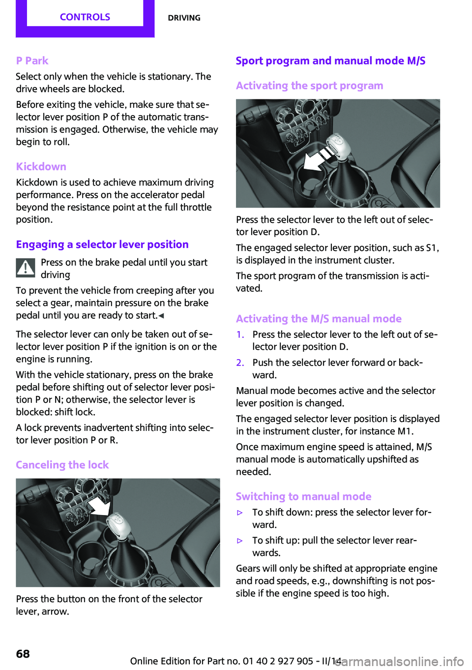
Press the selector lever to the left out of selec‐
tor lever position D.
The engaged selector lever position, such as S1,
is displayed in the instrument cluster.
The sport program of the transmission is acti‐
vated.
Activating the M/S manual mode
1.Press the selector lever to the left out of se‐
lector lever position D.2.Push the selector lever forward or back‐
ward.
Manual mode becomes active and the selector
lever position is changed.
The engaged selector lever position is displayed
in the instrument cluster, for instance M1.
Once maximum engine speed is attained, M/S
manual mode is automatically upshifted as
needed.
Switching to manual mode
▷To shift down: press the selector lever for‐
ward.▷To shift up: pull the selector lever rear‐
wards.
Gears will only be shifted at appropriate engine
and road speeds, e.g., downshifting is not pos‐
sible if the engine speed is too high.
Seite 68CONTROLSDriving68
Online Edition for Part no. 01 40 2 927 905 - II/14
Page 69 of 230
The selected selector lever position is briefly
displayed in the instrument cluster, followed by
the current one.
Manual mode M/S: prevent automatic
upshifting
Once maximum engine speed is attained, M/S
manual mode is automatically upshifted as
needed.
For vehicles with Sport automatic transmission,
automatic shift operations are not performed if
one of the following conditions is met:▷DSC is deactivated.▷TRACTION is activated.
In addition, the kickdown is deactivated.
Ending the sport program/manual
mode
Push the selector lever to the right.
D is displayed in the instrument cluster.
Shift paddles for Sport automatic
transmission
The shift paddles on the steering wheel allow
you to shift gears quickly while keeping both
hands on the steering wheel.
If the shift paddles on the steering wheel are
used to shift gears in automatic mode, the
transmission temporarily switches to manual
mode.
If the shift paddles are not used and the vehicle
is not accelerated for a certain time, the system
switches back into automatic mode if the selec‐
tor lever is in selector lever position D.
▷Shift up: pull right shift paddle.▷Shift down: pull left shift paddle.
The vehicle only shifts up or down at appropri‐
ate engine and road speeds, e.g., it does not
shift down if the engine speed is too high.
The selected gear is briefly displayed in the in‐
strument cluster, followed by the current gear.
Displays in the instrument cluster The selector lever position is dis‐
played, e.g.: P.
Manually release the transmission lock
Should the selector lever be blocked in selector
lever position P despite the ignition being
turned on, the brake being depressed and the
unlock button being pressed, the transmission
lock can be manually canceled:
Before unlocking the transmission lock man‐
ually, engage the parking brake forcefully to
prevent the vehicle from rolling away.
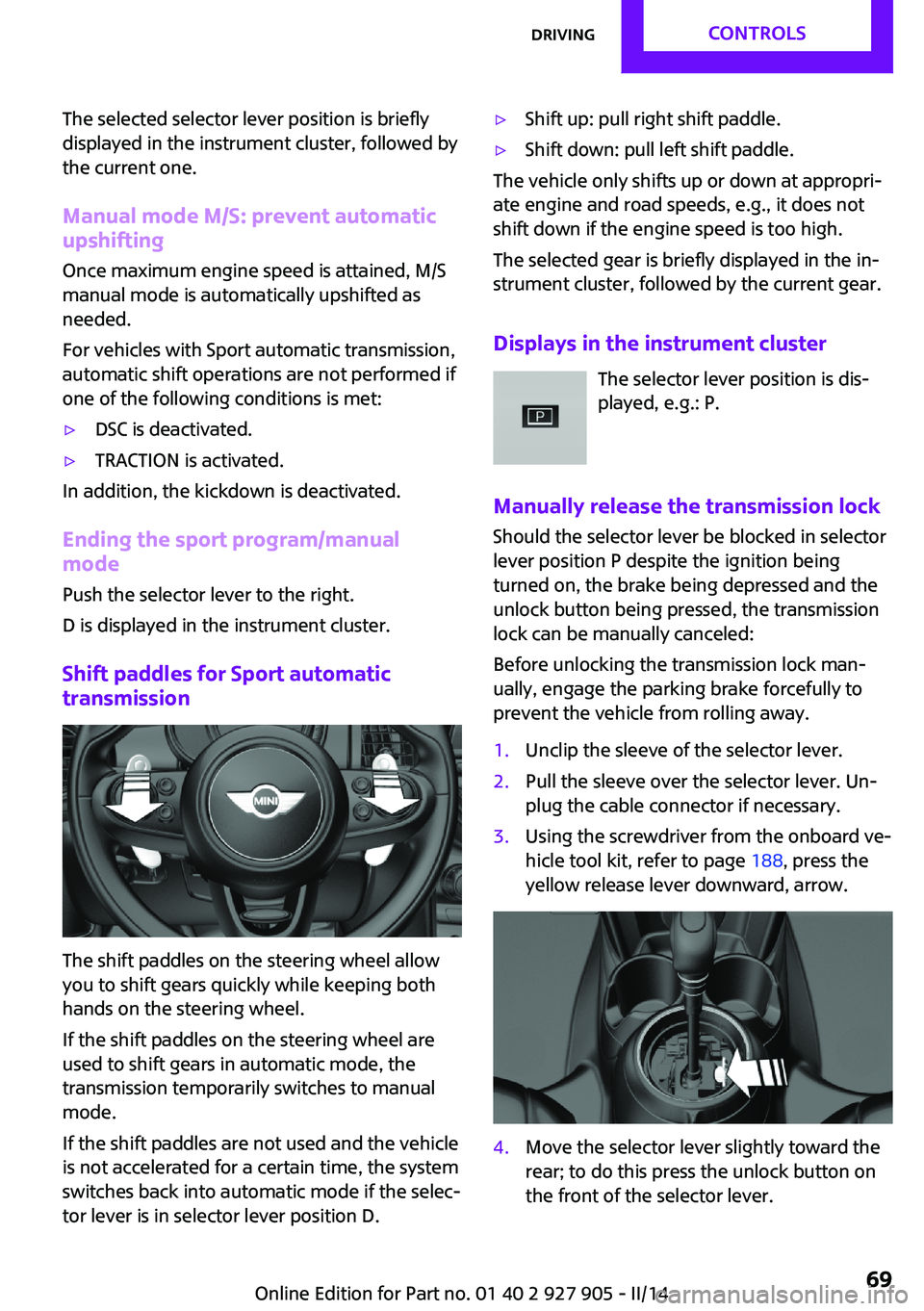
1.Unclip the sleeve of the selector lever.2.Pull the sleeve over the selector lever. Un‐
plug the cable connector if necessary.3.Using the screwdriver from the onboard ve‐
hicle tool kit, refer to page 188, press the
yellow release lever downward, arrow.4.Move the selector lever slightly toward the
rear; to do this press the unlock button on
the front of the selector lever.Seite 69DrivingCONTROLS69
Online Edition for Part no. 01 40 2 927 905 - II/14
Page 71 of 230
DisplaysVehicle equipment
All standard, country-specific and optional
equipment that is offered in the model series is
described in this chapter. Therefore, equipmentis also described that is not available in a vehi‐
cle, e. g., because of the selected optional
equipment or country variant. This also applies
for safety-related functions and systems.
Instrument cluster
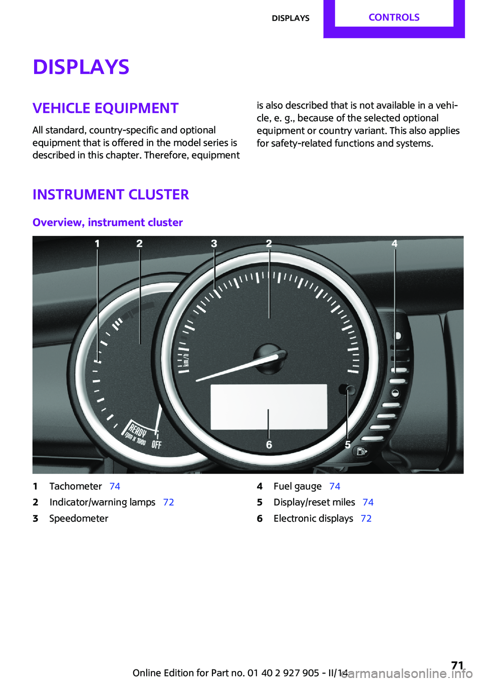
Overview, instrument cluster
1Tachometer 742Indicator/warning lamps 723Speedometer4Fuel gauge 745Display/reset miles 746Electronic displays 72Seite 71DisplaysCONTROLS71
Online Edition for Part no. 01 40 2 927 905 - II/14
Page 72 of 230

Electronic displays1Driver assistance systems
Messages, e.g. Check Control
Time 75
External temperature 75
Selection lists 78
Miles/trip miles 74Computer 792Selector lever position display 67
Gear shift indicator 763Driving Dynamics Control 108
StatusCheck Control
The concept
The Check Control system monitors functions in
the vehicle and notifies you of malfunctions in the monitored systems.
A Check Control message is displayed as a com‐
bination of indicator or warning lamps and text
messages in the instrument cluster and in the
Head-up Display.
In addition, an acoustic signal may be output
and a text message may appear on the Control Display.Indicator/warning lamps
The indicator and warning lamps can light up in
a variety of combinations and colors.
Several of the lamps are checked for proper
functioning and light up temporarily when the
engine is started or the ignition is switched on.
Overview: indicator/warning lampsSymbolFunction or systemTurn signalFront fog lampsSeite 72CONTROLSDisplays72
Online Edition for Part no. 01 40 2 927 905 - II/14
Page 73 of 230
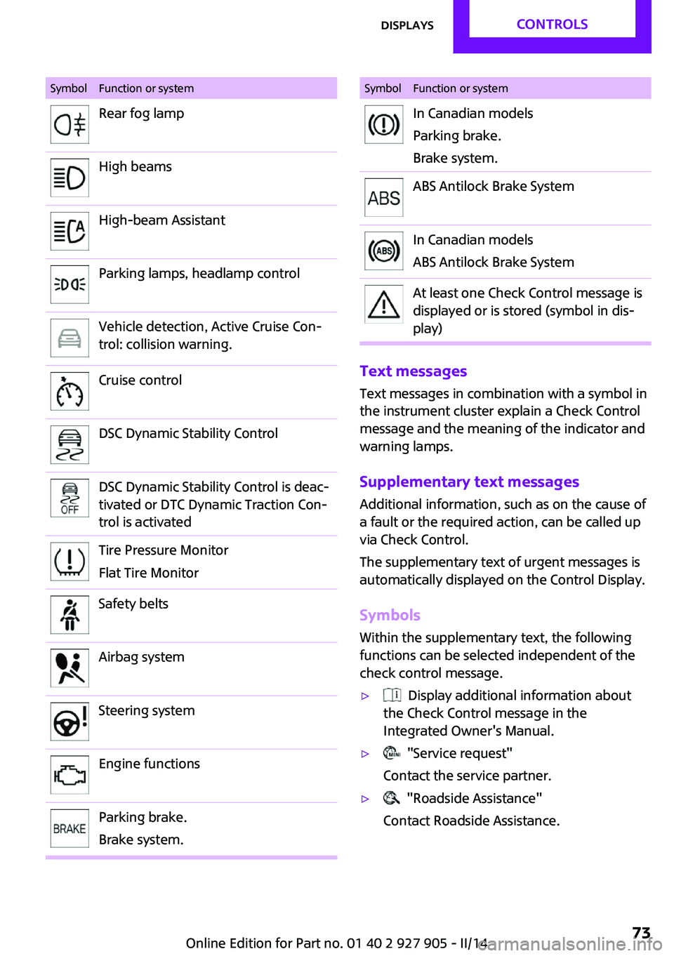
SymbolFunction or systemRear fog lampHigh beamsHigh-beam AssistantParking lamps, headlamp controlVehicle detection, Active Cruise Con‐
trol: collision warning.Cruise controlDSC Dynamic Stability ControlDSC Dynamic Stability Control is deac‐
tivated or DTC Dynamic Traction Con‐
trol is activatedTire Pressure Monitor
Flat Tire MonitorSafety beltsAirbag systemSteering systemEngine functionsParking brake.
Brake system.SymbolFunction or systemIn Canadian models
Parking brake.
Brake system.ABS Antilock Brake SystemIn Canadian models
ABS Antilock Brake SystemAt least one Check Control message is
displayed or is stored (symbol in dis‐
play)
Text messages
Text messages in combination with a symbol in
the instrument cluster explain a Check Control
message and the meaning of the indicator and
warning lamps.
Supplementary text messages Additional information, such as on the cause of
a fault or the required action, can be called up
via Check Control.
The supplementary text of urgent messages is
automatically displayed on the Control Display.
Symbols Within the supplementary text, the following
functions can be selected independent of the
check control message.
▷ Display additional information about
the Check Control message in the
Integrated Owner's Manual.▷ "Service request"
Contact the service partner.▷ "Roadside Assistance"
Contact Roadside Assistance.Seite 73DisplaysCONTROLS73
Online Edition for Part no. 01 40 2 927 905 - II/14
Page 74 of 230

Hiding Check Control messages
Press the onboard computer button on the turn
signal lever.
▷Some Check Control messages are dis‐
played continuously and are not cleared
until the malfunction is eliminated. If sev‐
eral malfunctions occur at once, the mes‐
sages are displayed consecutively.
These messages can be hidden for approx.
8 seconds. After this time, they are dis‐
played again automatically.▷Other Check Control messages are hidden
automatically after approx. 20 seconds.
They are stored and can be displayed again
later.
Displaying stored Check Control
messages
1. "Vehicle Info"2."Vehicle status"3. "Check Control"4.Select the text message.
Messages after trip completion
Special messages that are displayed during
driving are displayed again after the ignition is
switched off.
Fuel gauge
The vehicle inclination may
cause the display to vary.
The arrow beside the fuel pump
symbol shows which side of the
vehicle the fuel filler flap is on.
Hints on refueling, refer to page 164.
Tachometer
Always avoid engine speeds in the red warning
field. In this range, the fuel supply is interrupted
to protect the engine.
Engine oil temperature If the engine oil along with the engine becomes
too hot, a Check Control message is displayed.
Coolant temperature If the coolant along with the engine becomes
too hot, a Check Control message is displayed.
Check the coolant level, refer to page 185.
Odometer and trip odom‐
eter
The concept
Odometer and trip odometer are displayed in
the instrument cluster.
Resetting the trip odometer Press the knob.▷The odometer is displayed
when the ignition is switched
off.Seite 74CONTROLSDisplays74
Online Edition for Part no. 01 40 2 927 905 - II/14
Page 75 of 230
▷When the ignition is switched on, the trip
odometer is reset.
External temperature
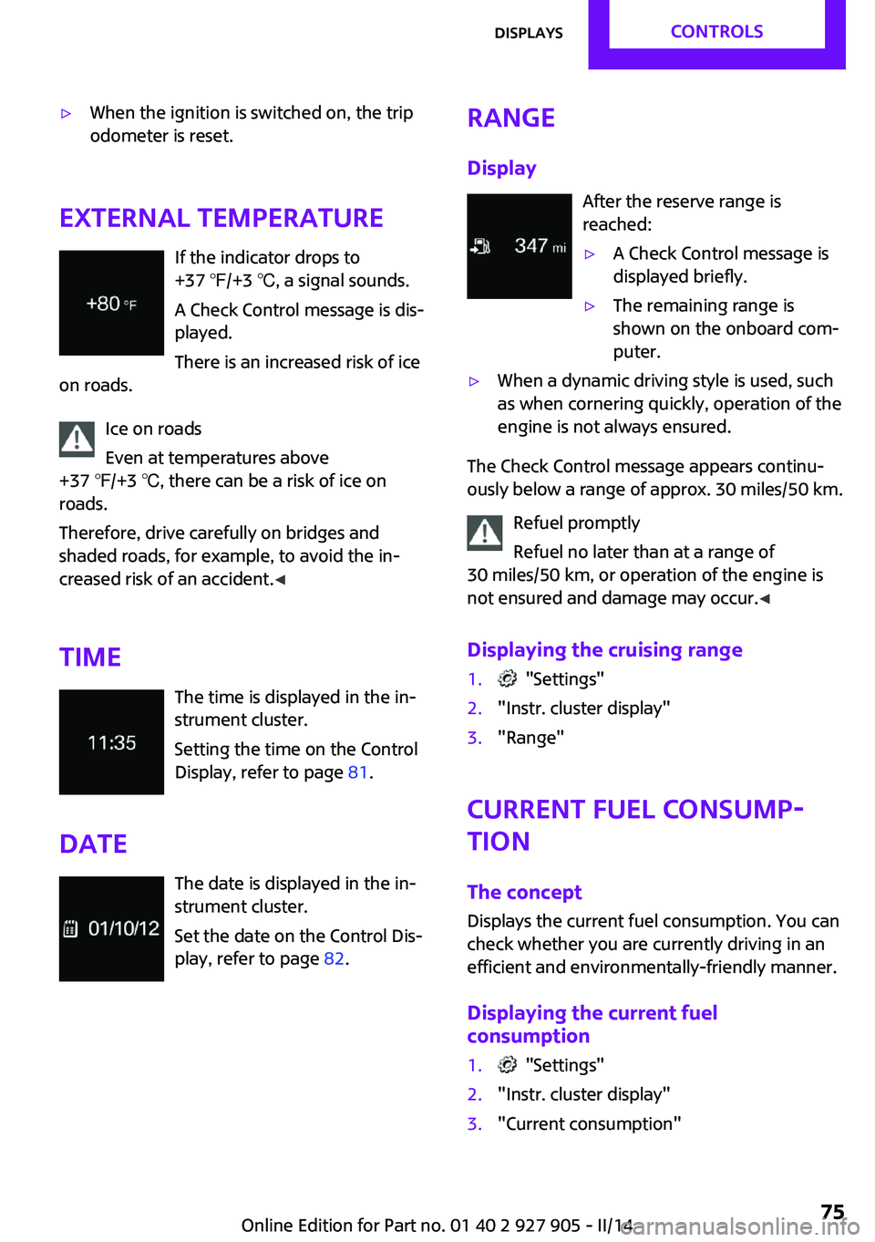
If the indicator drops to
+37 ℉/+3 ℃, a signal sounds.
A Check Control message is dis‐
played.
There is an increased risk of ice
on roads.
Ice on roads
Even at temperatures above
+37 ℉/+3 ℃, there can be a risk of ice on
roads.
Therefore, drive carefully on bridges and
shaded roads, for example, to avoid the in‐
creased risk of an accident. ◀
Time The time is displayed in the in‐
strument cluster.
Setting the time on the Control
Display, refer to page 81.
Date The date is displayed in the in‐
strument cluster.
Set the date on the Control Dis‐
play, refer to page 82.
Range
Display After the reserve range is
reached:▷A Check Control message is
displayed briefly.▷The remaining range is
shown on the onboard com‐
puter.▷When a dynamic driving style is used, such
as when cornering quickly, operation of the
engine is not always ensured.
The Check Control message appears continu‐
ously below a range of approx. 30 miles/50 km.
Refuel promptly
Refuel no later than at a range of
30 miles/50 km, or operation of the engine is
not ensured and damage may occur. ◀
Displaying the cruising range
1. "Settings"2."Instr. cluster display"3."Range"
Current fuel consump‐
tion
The concept
Displays the current fuel consumption. You can
check whether you are currently driving in an
efficient and environmentally-friendly manner.
Displaying the current fuel
consumption
1. "Settings"2."Instr. cluster display"3."Current consumption"Seite 75DisplaysCONTROLS75
Online Edition for Part no. 01 40 2 927 905 - II/14
Page 76 of 230
Service requirementsThe concept
The driving distance or the time to the next
scheduled maintenance is displayed briefly in the instrument cluster after the ignition is
switched on.
The current service requirements can be read
out from the remote control by the service spe‐ cialist.
Display
Detailed information on service
requirements
More information on the scope of service re‐
quired can be displayed on the Control Display.1. "Vehicle Info"2."Vehicle status"3. "Service required"
Required maintenance procedures and le‐
gally mandated inspections are displayed.4.Select an entry to call up detailed informa‐
tion.
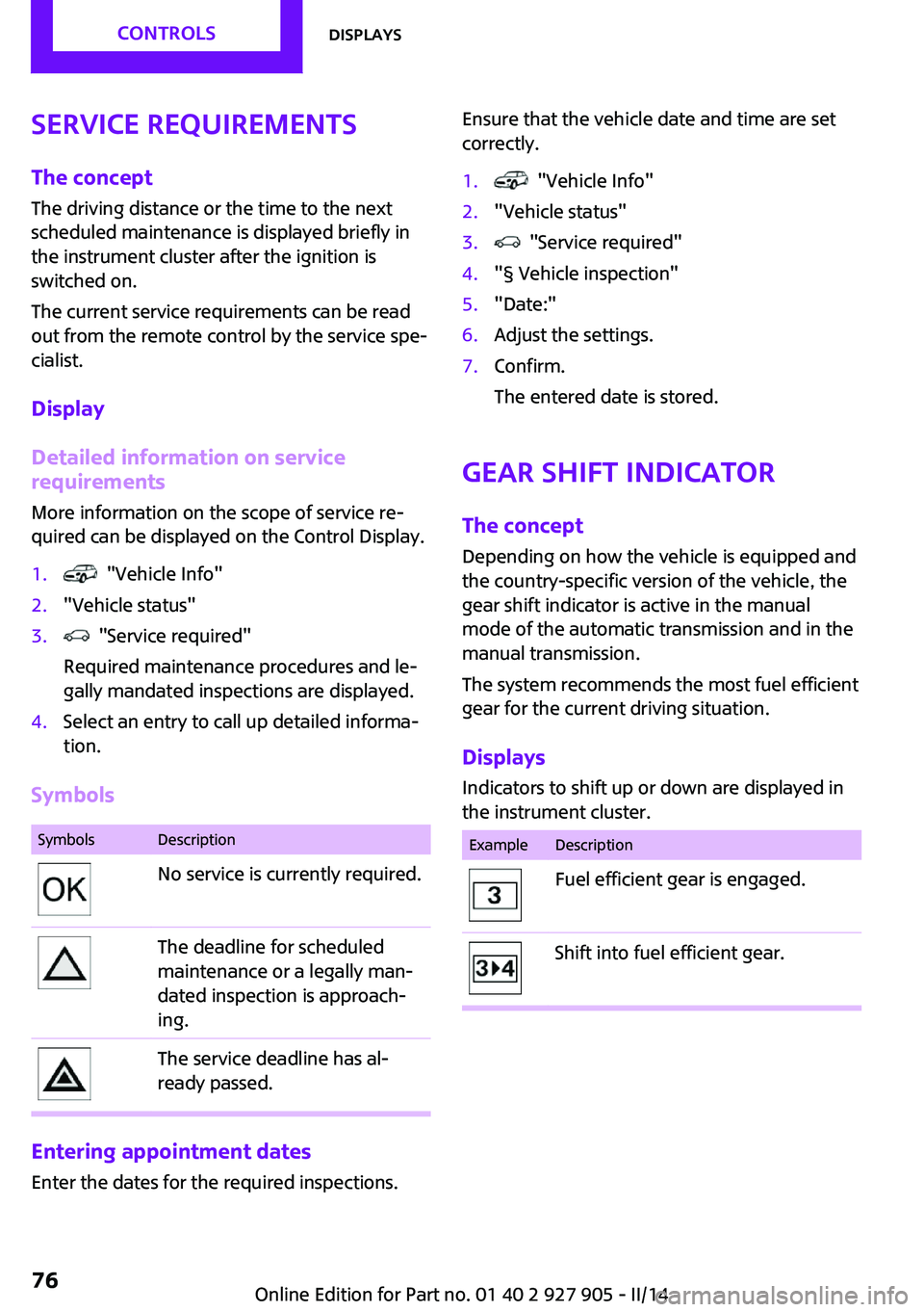
Symbols
SymbolsDescriptionNo service is currently required.The deadline for scheduled
maintenance or a legally man‐
dated inspection is approach‐
ing.The service deadline has al‐
ready passed.
Entering appointment dates
Enter the dates for the required inspections.
Ensure that the vehicle date and time are set
correctly.1. "Vehicle Info"2."Vehicle status"3. "Service required"4."§ Vehicle inspection"5."Date:"6.Adjust the settings.7.Confirm.
The entered date is stored.
Gear shift indicator
The concept
Depending on how the vehicle is equipped and
the country-specific version of the vehicle, the
gear shift indicator is active in the manual
mode of the automatic transmission and in the
manual transmission.
The system recommends the most fuel efficient
gear for the current driving situation.
Displays Indicators to shift up or down are displayed in
the instrument cluster.
ExampleDescriptionFuel efficient gear is engaged.Shift into fuel efficient gear.Seite 76CONTROLSDisplays76
Online Edition for Part no. 01 40 2 927 905 - II/14