change wheel MINI COOPER 2014 Owners Manual
[x] Cancel search | Manufacturer: MINI, Model Year: 2014, Model line: COOPER, Model: MINI COOPER 2014Pages: 230, PDF Size: 11.58 MB
Page 42 of 230
AdjustingUnlocking The settings are saved in the active profile. Per‐
sonal Profile, refer to page 35.
Doors1. "Settings"2."Doors/key"3. Select the symbol.4.Select the desired function.▷"Driver's door only"
Only the driver's door and the fuel filler
flap are unlocked. Pressing again un‐
locks the entire vehicle.▷"All doors"
The entire vehicle is unlocked.▷"Comfort access"
The entire vehicle is unlocked. Pressing
again lowers the window when the
door is subsequently opened.
Tailgate
Depending on the equipment version and
country variant, this setting is not offered in
some cases.
1. "Settings"2."Doors/key"3. Select the symbol.4.Select the desired function.▷"Tailgate"
Only the tailgate is unlocked.▷"Tailgate + door(s)"
The tailgate and the doors are un‐
locked.Locking
The settings are saved in the active profile. Per‐
sonal Profile, refer to page 35.1. "Settings"2."Doors/key"3.Select the desired setting.▷"Lock if no door is opened"
The vehicle locks automatically after a
short period of time if a door is not
opened.▷"Lock after start driving"
The vehicle locks automatically after
you drive away.
Confirmation signals from the vehicle
1."Settings"2."Doors/key"3.Select the desired setting.▷"Acoustic sig. lock/unlock"
The unlocking is acknowledged by one
honk of the horn.▷"Flash when lock/unlock"
The unlocking is acknowledged by two
flashes, the locking by one.
Alarm system
The concept
When the vehicle is locked, the vehicle alarm
system responds to:
▷Opening of a door, the hood or the tailgate.▷Movements in the vehicle.▷Changes in the vehicle tilt, e.g., during at‐
tempts to steal a wheel or when towing the
car.▷Interruptions in battery voltage.
The alarm system briefly indicates tampering:
▷Acoustic alarm.Seite 42CONTROLSOpening and closing42
Online Edition for Part no. 01 40 2 927 905 - II/14
Page 62 of 230
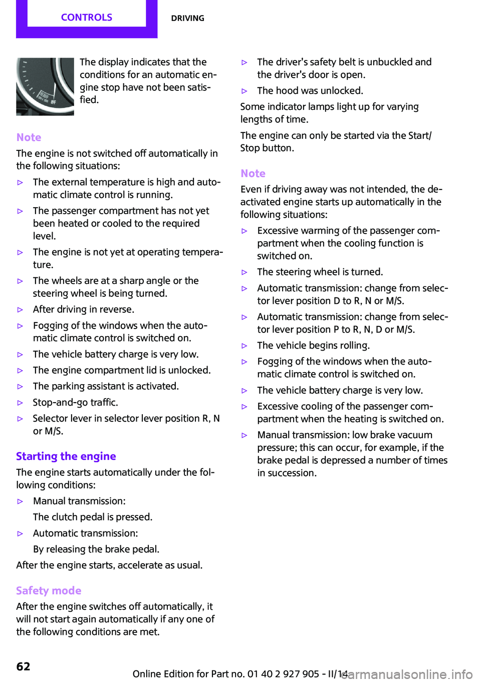
The display indicates that the
conditions for an automatic en‐
gine stop have not been satis‐
fied.
Note
The engine is not switched off automatically in
the following situations:▷The external temperature is high and auto‐
matic climate control is running.▷The passenger compartment has not yet
been heated or cooled to the required
level.▷The engine is not yet at operating tempera‐
ture.▷The wheels are at a sharp angle or the
steering wheel is being turned.▷After driving in reverse.▷Fogging of the windows when the auto‐
matic climate control is switched on.▷The vehicle battery charge is very low.▷The engine compartment lid is unlocked.▷The parking assistant is activated.▷Stop-and-go traffic.▷Selector lever in selector lever position R, N
or M/S.
Starting the engine
The engine starts automatically under the fol‐
lowing conditions:
▷Manual transmission:
The clutch pedal is pressed.▷Automatic transmission:
By releasing the brake pedal.
After the engine starts, accelerate as usual.
Safety mode
After the engine switches off automatically, it
will not start again automatically if any one of
the following conditions are met.
▷The driver's safety belt is unbuckled and
the driver's door is open.▷The hood was unlocked.
Some indicator lamps light up for varying
lengths of time.
The engine can only be started via the Start/
Stop button.
Note
Even if driving away was not intended, the de‐
activated engine starts up automatically in the
following situations:
▷Excessive warming of the passenger com‐
partment when the cooling function is
switched on.▷The steering wheel is turned.▷Automatic transmission: change from selec‐
tor lever position D to R, N or M/S.▷Automatic transmission: change from selec‐
tor lever position P to R, N, D or M/S.▷The vehicle begins rolling.▷Fogging of the windows when the auto‐
matic climate control is switched on.▷The vehicle battery charge is very low.▷Excessive cooling of the passenger com‐
partment when the heating is switched on.▷Manual transmission: low brake vacuum
pressure; this can occur, for example, if the
brake pedal is depressed a number of times
in succession.Seite 62CONTROLSDriving62
Online Edition for Part no. 01 40 2 927 905 - II/14
Page 68 of 230
P Park
Select only when the vehicle is stationary. The
drive wheels are blocked.
Before exiting the vehicle, make sure that se‐
lector lever position P of the automatic trans‐
mission is engaged. Otherwise, the vehicle may
begin to roll.
Kickdown Kickdown is used to achieve maximum driving
performance. Press on the accelerator pedal
beyond the resistance point at the full throttle
position.
Engaging a selector lever position Press on the brake pedal until you start
driving
To prevent the vehicle from creeping after you select a gear, maintain pressure on the brake
pedal until you are ready to start. ◀
The selector lever can only be taken out of se‐
lector lever position P if the ignition is on or the
engine is running.
With the vehicle stationary, press on the brake
pedal before shifting out of selector lever posi‐
tion P or N; otherwise, the selector lever is
blocked: shift lock.
A lock prevents inadvertent shifting into selec‐
tor lever position P or R.
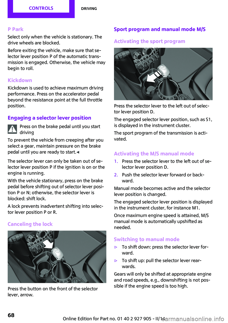
Canceling the lock
Press the button on the front of the selector
lever, arrow.
Sport program and manual mode M/S
Activating the sport program
Press the selector lever to the left out of selec‐
tor lever position D.
The engaged selector lever position, such as S1,
is displayed in the instrument cluster.
The sport program of the transmission is acti‐
vated.
Activating the M/S manual mode
1.Press the selector lever to the left out of se‐
lector lever position D.2.Push the selector lever forward or back‐
ward.
Manual mode becomes active and the selector
lever position is changed.
The engaged selector lever position is displayed
in the instrument cluster, for instance M1.
Once maximum engine speed is attained, M/S
manual mode is automatically upshifted as
needed.
Switching to manual mode
▷To shift down: press the selector lever for‐
ward.▷To shift up: pull the selector lever rear‐
wards.
Gears will only be shifted at appropriate engine
and road speeds, e.g., downshifting is not pos‐
sible if the engine speed is too high.
Seite 68CONTROLSDriving68
Online Edition for Part no. 01 40 2 927 905 - II/14
Page 78 of 230

Speed limit detectionThe last speed limit detected.
Without a navigation system the
traffic signals are grayed out af‐
ter curves or longer stretches of
roadway.
With navigation system: speed
limit detection is not available.
Without navigation system:
speed limit detection switched
on, but no speed limit or cancel‐
lation is detected.
Speed limit detection can also be displayed in
the Head-up Display.
No Passing Information▷Start of No Passing zone.▷End of No Passing zone.▷No Passing Information not
available.
No Passing Information can also be displayed in
the Head-up Display.
System limits The system may not be fully functional and
may provide incorrect information in the fol‐
lowing situations:
▷In heavy fog, rain or snowfall.▷When signs are concealed by objects.▷When driving very close to the vehicle in
front of you.▷When driving toward bright lights.▷When the windshield behind the interior
rearview mirror is fogged over, dirty or cov‐
ered by a sticker, etc.▷In the event of incorrect detection by the
camera.▷If the speed limits stored in the navigation
system are incorrect.▷In areas not covered by the navigation sys‐
tem.▷When roads differ from the navigation, such
as due to changes in the road network.▷When passing buses or trucks with a speed
sticker.▷If the traffic signs are non-conforming.▷During calibration of the camera immedi‐
ately after vehicle shipment.
Selection lists in the in‐
strument cluster
The concept
The following can be displayed or operated us‐
ing the buttons on the steering wheel and the
display in the instrument cluster:
▷Current audio source.▷Redial on telephone.▷Activation of the voice activation system.
In addition, programs of the Driving Dynamics
Control are displayed.
Display
Seite 78CONTROLSDisplays78
Online Edition for Part no. 01 40 2 927 905 - II/14
Page 90 of 230
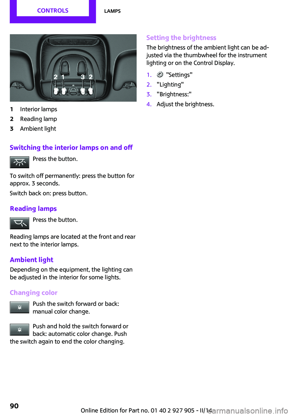
1Interior lamps2Reading lamp3Ambient light
Switching the interior lamps on and offPress the button.
To switch off permanently: press the button for
approx. 3 seconds.
Switch back on: press button.
Reading lamps Press the button.
Reading lamps are located at the front and rear
next to the interior lamps.
Ambient light
Depending on the equipment, the lighting can
be adjusted in the interior for some lights.
Changing color Push the switch forward or back:
manual color change.
Push and hold the switch forward or
back: automatic color change. Push
the switch again to end the color changing.
Setting the brightness
The brightness of the ambient light can be ad‐
justed via the thumbwheel for the instrument
lighting or on the Control Display.1. "Settings"2."Lighting"3."Brightness:"4.Adjust the brightness.Seite 90CONTROLSLamps90
Online Edition for Part no. 01 40 2 927 905 - II/14
Page 94 of 230
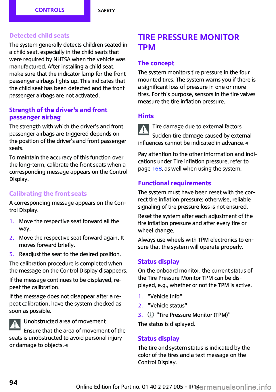
Detected child seatsThe system generally detects children seated in
a child seat, especially in the child seats that
were required by NHTSA when the vehicle was
manufactured. After installing a child seat,
make sure that the indicator lamp for the front
passenger airbags lights up. This indicates that
the child seat has been detected and the front
passenger airbags are not activated.
Strength of the driver's and front
passenger airbag
The strength with which the driver's and front
passenger airbags are triggered depends on
the position of the driver's and front passenger
seats.
To maintain the accuracy of this function over
the long-term, calibrate the front seats when a
corresponding message appears on the Control
Display.
Calibrating the front seats
A corresponding message appears on the Con‐
trol Display.1.Move the respective seat forward all the
way.2.Move the respective seat forward again. It
moves forward briefly.3.Readjust the seat to the desired position.
The calibration procedure is completed when
the message on the Control Display disappears.
If the message continues to be displayed, re‐
peat the calibration.
If the message does not disappear after a re‐
peat calibration, have the system checked as
soon as possible.
Unobstructed area of movement
Ensure that the area of movement of the
seats is unobstructed to avoid personal injury
or damage to objects. ◀
Tire Pressure Monitor
TPM
The concept The system monitors tire pressure in the four
mounted tires. The system warns you if there is
a significant loss of pressure in one or more
tires. For this purpose, sensors in the tire valves
measure the tire inflation pressure.
Hints Tire damage due to external factors
Sudden tire damage caused by external
influences cannot be indicated in advance. ◀
Pay attention to the other information and indi‐
cations under Tire inflation pressure, refer to
page 168, as well when using the system.
Functional requirements The system must have been reset with the cor‐
rect tire inflation pressure; otherwise, reliable
signaling of tire pressure loss is not ensured.
Reset the system after each adjustment of the
tire inflation pressure and after every tire or
wheel change.
Always use wheels with TPM electronics to en‐
sure that the system will operate properly.
Status display On the onboard monitor, the current status of
the Tire Pressure Monitor TPM can be dis‐
played, e.g., whether or not the TPM is active.1."Vehicle Info"2."Vehicle status"3. "Tire Pressure Monitor (TPM)"
The status is displayed.
Status display The tire and system status is indicated by the
color of the tires and a text message on the
Control Display.
Seite 94CONTROLSSafety94
Online Edition for Part no. 01 40 2 927 905 - II/14
Page 95 of 230

All wheels greenSystem is active and will issue a warning rela‐
tive to the tire inflation pressures stored during
the last reset.
One wheel is yellow
A flat tire or major drop in inflation pressure in
the indicated tire.
All wheels are yellow
A flat tire or major drop in inflation pressure in
several tires.
Wheels, gray
The system cannot detect a flat tire due to a
malfunction.
Status information
The status display additionally shows the cur‐
rent tire inflation pressures. The values shown
are current measurement values and may vary
depending on driving style or weather condi‐
tions.
Carry out reset
Reset the system after each adjustment of the
tire inflation pressure and after every tire or
wheel change.1."Vehicle Info"2."Vehicle status"3. "Perform reset"4.Start the engine - do not drive away.5.Reset the tire pressure using "Perform
reset".6.Drive away.
The tires are shown in gray and the status is
displayed.
After driving faster than 19 mph/30 km/h for a
short period, the tire inflation pressures set are
accepted as reference values. The resetting
process is completed automatically during driv‐
ing. After successful completion of the reset,
the tires appear in green on the Control Display
and "Tire Pressure Monitor (TPM) active" is dis‐
played.
The progress of the reset is displayed.
The trip can be interrupted at any time. If you
drive away again, the reset resumes automati‐
cally.
Low tire pressure message The yellow warning lamp lights up. A
Check Control message is displayed.▷There is a flat tire or a major loss in
tire inflation pressure.▷A reset of the system was not carried out
after a wheel was changed. The system
therefore issues a warning based on the tire
pressures before the last reset.1.Reduce your speed and stop cautiously.
Avoid sudden braking and steering maneu‐
vers.2.Check whether the vehicle is fitted with
regular tires or run-flat tires.
Run-flat tires, refer to page 175, are la‐
beled with a circular symbol containing the
letters RSC marked on the tire sidewall.
Do not continue driving without run-flat
tires
Do not continue driving if the vehicle is not
equipped with run-flat tires; continued driving
may result in serious accidents. ◀
When a low inflation pressure is indicated, DSC
Dynamic Stability Control is switched on if nec‐
essary.
Actions in the event of a flat tire Normal tires
1.Identify the damaged tire.
Do this by checking the air pressure in all
four tires.Seite 95SafetyCONTROLS95
Online Edition for Part no. 01 40 2 927 905 - II/14
Page 96 of 230
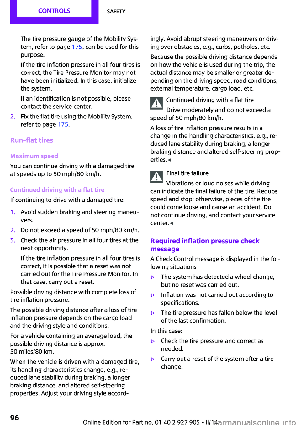
The tire pressure gauge of the Mobility Sys‐
tem, refer to page 175, can be used for this
purpose.
If the tire inflation pressure in all four tires is
correct, the Tire Pressure Monitor may not
have been initialized. In this case, initialize
the system.
If an identification is not possible, please
contact the service center.2.Fix the flat tire using the Mobility System,
refer to page 175.
Run-flat tires
Maximum speed
You can continue driving with a damaged tire
at speeds up to 50 mph/80 km/h.
Continued driving with a flat tire
If continuing to drive with a damaged tire:
1.Avoid sudden braking and steering maneu‐
vers.2.Do not exceed a speed of 50 mph/80 km/h.3.Check the air pressure in all four tires at the
next opportunity.
If the tire inflation pressure in all four tires is
correct, it is possible that a reset was not
carried out for the Tire Pressure Monitor. In
that case, carry out a reset.
Possible driving distance with complete loss of
tire inflation pressure:
The possible driving distance after a loss of tire
inflation pressure depends on the cargo load
and the driving style and conditions.
For a vehicle containing an average load, the
possible driving distance is approx.
50 miles/80 km.
When the vehicle is driven with a damaged tire,
its handling characteristics change, e.g., re‐
duced lane stability during braking, a longer
braking distance, and altered self-steering
properties. Adjust your driving style accord‐
ingly. Avoid abrupt steering maneuvers or driv‐
ing over obstacles, e.g., curbs, potholes, etc.
Because the possible driving distance depends
on how the vehicle is used during the trip, the
actual distance may be smaller or greater de‐
pending on the driving speed, road conditions,
external temperature, cargo load, etc.
Continued driving with a flat tire
Drive moderately and do not exceed a
speed of 50 mph/80 km/h.
A loss of tire inflation pressure results in a
change in the handling characteristics, e.g., re‐
duced lane stability during braking, a longer
braking distance and altered self-steering prop‐
erties. ◀
Final tire failure
Vibrations or loud noises while driving
can indicate the final failure of the tire. Reduce
speed and stop; otherwise, pieces of the tire
could come loose and cause an accident. Do
not continue driving, and contact your service
center. ◀
Required inflation pressure check
message
A Check Control message is displayed in the fol‐
lowing situations▷The system has detected a wheel change,
but no reset was carried out.▷Inflation was not carried out according to
specifications.▷The tire pressure has fallen below the level
of the last confirmation.
In this case:
▷Check the tire pressure and correct as
needed.▷Carry out a reset of the system after a tire
change.Seite 96CONTROLSSafety96
Online Edition for Part no. 01 40 2 927 905 - II/14
Page 98 of 230
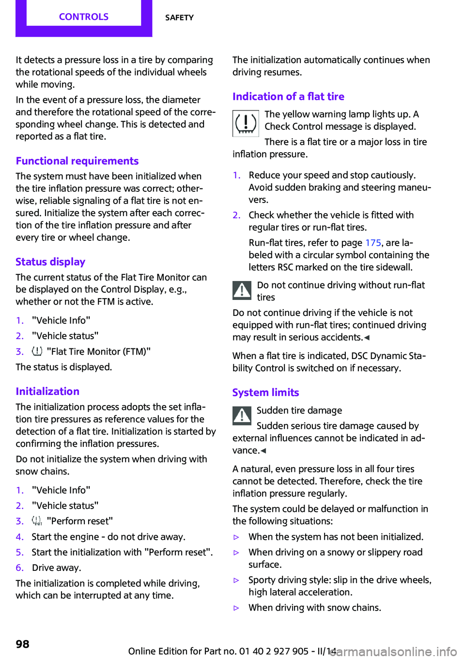
It detects a pressure loss in a tire by comparing
the rotational speeds of the individual wheels
while moving.
In the event of a pressure loss, the diameter
and therefore the rotational speed of the corre‐
sponding wheel change. This is detected and
reported as a flat tire.
Functional requirements The system must have been initialized when
the tire inflation pressure was correct; other‐
wise, reliable signaling of a flat tire is not en‐
sured. Initialize the system after each correc‐
tion of the tire inflation pressure and after
every tire or wheel change.
Status display
The current status of the Flat Tire Monitor can
be displayed on the Control Display, e.g.,
whether or not the FTM is active.1."Vehicle Info"2."Vehicle status"3. "Flat Tire Monitor (FTM)"
The status is displayed.
Initialization The initialization process adopts the set infla‐
tion tire pressures as reference values for the
detection of a flat tire. Initialization is started by
confirming the inflation pressures.
Do not initialize the system when driving with
snow chains.
1."Vehicle Info"2."Vehicle status"3. "Perform reset"4.Start the engine - do not drive away.5.Start the initialization with "Perform reset".6.Drive away.
The initialization is completed while driving,
which can be interrupted at any time.
The initialization automatically continues when
driving resumes.
Indication of a flat tire The yellow warning lamp lights up. A
Check Control message is displayed.
There is a flat tire or a major loss in tire
inflation pressure.1.Reduce your speed and stop cautiously.
Avoid sudden braking and steering maneu‐
vers.2.Check whether the vehicle is fitted with
regular tires or run-flat tires.
Run-flat tires, refer to page 175, are la‐
beled with a circular symbol containing the
letters RSC marked on the tire sidewall.
Do not continue driving without run-flat
tires
Do not continue driving if the vehicle is not
equipped with run-flat tires; continued driving
may result in serious accidents. ◀
When a flat tire is indicated, DSC Dynamic Sta‐
bility Control is switched on if necessary.
System limits Sudden tire damage
Sudden serious tire damage caused by
external influences cannot be indicated in ad‐
vance. ◀
A natural, even pressure loss in all four tires
cannot be detected. Therefore, check the tire
inflation pressure regularly.
The system could be delayed or malfunction in
the following situations:
▷When the system has not been initialized.▷When driving on a snowy or slippery road
surface.▷Sporty driving style: slip in the drive wheels,
high lateral acceleration.▷When driving with snow chains.Seite 98CONTROLSSafety98
Online Edition for Part no. 01 40 2 927 905 - II/14
Page 110 of 230
Driving comfortVehicle equipment
All standard, country-specific and optional
equipment that is offered in the model series is
described in this chapter. Therefore, equipment
is also described that is not available in a vehi‐
cle, e. g., because of the selected optional
equipment or country variant. This also applies
for safety-related functions and systems.
Camera-based cruise con‐
trol, ACC
The concept
This system can be used to select a desired
speed that the vehicle will maintain automati‐
cally on clear roads.
To the extent possible, the system automati‐
cally adjusts the speed to a slower vehicle
ahead of you.
A camera on the interior rear view mirror is
used to detect vehicles driving ahead.
The distance that the vehicle maintains to the
vehicle ahead of you can be varied.
For safety reasons, it depends on the speed.
To maintain a certain distance, the system au‐
tomatically decelerates, applies the brakes
lightly, or accelerates again if the vehicle ahead
begins moving faster.
As soon as the road is clear, it accelerates to the
desired speed.
The speed is also maintained on downhill gradi‐
ents, but may not be maintained on uphill
slopes if engine power is insufficient.
General information
Depending on the set drive mode, refer to
page 108, the characteristics of the cruise con‐
trol can change in certain areas.Hints
Personal responsibility
Even an active system does not release
the driver from personal responsibility for the
driving process, especially for lane tracking, adaptation of speed, distance and driving style
to the traffic conditions.
Because of technical system limits, the system
cannot independently react appropriately in all
traffic situations.
Monitor the driving process, the surrounding
area and what is occurring in traffic continu‐
ously and attentively and actively intervene as
required, e.g., by braking, steering or making
an evasive maneuver. ◀
Unfavorable weather conditions
In the event of unfavorable weather and
light conditions, for instance if there is rain,
snowfall, slush, fog or glare, this may result in
poorer recognition of traffic situations as well
as short-term interruptions for vehicles that are
already detected. Drive attentively, and react to
the current traffic events. Intervene actively
when necessary, e.g., by braking, steering or
making an evasive maneuver, otherwise, there
is danger of an accident. ◀
At a glance
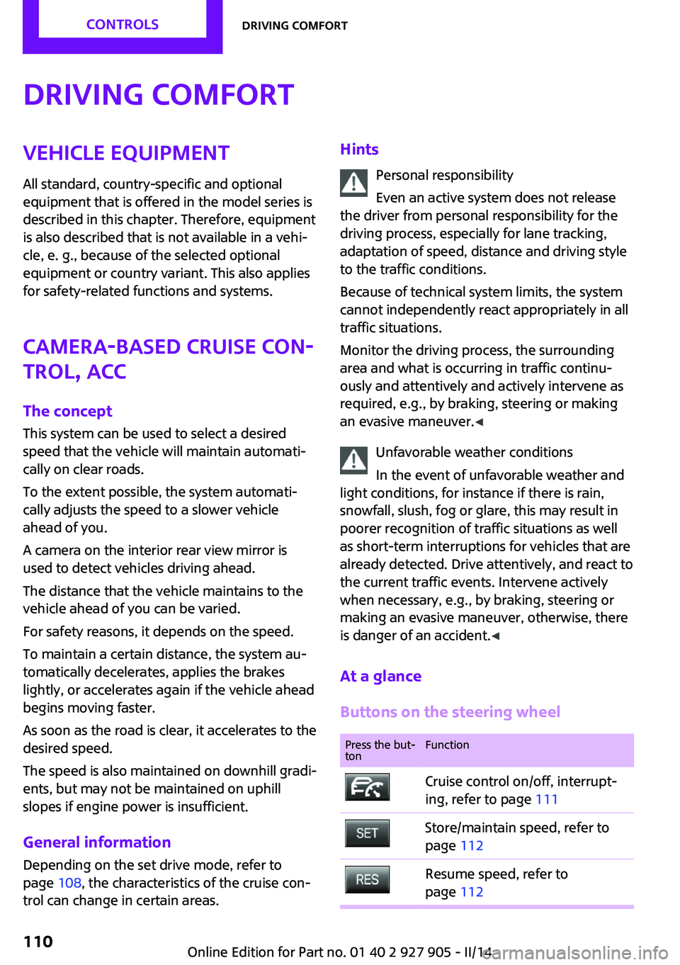
Buttons on the steering wheelPress the but‐
tonFunctionCruise control on/off, interrupt‐
ing, refer to page 111Store/maintain speed, refer to
page 112Resume speed, refer to
page 112Seite 110CONTROLSDriving comfort110
Online Edition for Part no. 01 40 2 927 905 - II/14