turn signal MINI COOPER 2014 Owners Manual
[x] Cancel search | Manufacturer: MINI, Model Year: 2014, Model line: COOPER, Model: MINI COOPER 2014Pages: 230, PDF Size: 11.58 MB
Page 15 of 230

Store speed Resume speed 112, 117Set speed 112, 116Reduce distance 116Increase distance 1106Steering column stalk, leftTurn signal 64High beams, head‐
lamp flasher 64Roadside parking lamps 86Computer 797Instrument cluster 718Steering column stalk, rightWindshield wipers 64Rain sensor 65Cleaning windows 66Rear window wiper 66Cleaning rear window 669Steering wheel buttons, rightVoice activation 26TelephoneConfirm the selection 78Move selection up 78Move selection down 78Increase volumeReduce volume10Horn11Adjust the steering wheel 5412Unlock hood 180Seite 15CockpitAT A GLANCE15
Online Edition for Part no. 01 40 2 927 905 - II/14
Page 36 of 230

Adjusting
The following settings are stored in a profile.▷Radio: stored stations, station listened to
last.▷Assignment of the programmable memory
buttons.▷Tone settings.▷Audio source listened to last.▷Unlocking the vehicle: driver door or entire
vehicle.▷Locking the vehicle: if no door is open or af‐
ter starting off.▷Welcome lamps: on/off.▷Triple turn signal activation: on/off.▷Headlamp courtesy delay feature: time set‐
ting.▷Language on the Control Display.▷Daytime running lights: on/off.▷Air conditioner/Automatic climate control:
settings.▷Navigation: map views, route criteria, voice
output on/off.▷Park Distance Control PDC: signal tone vol‐
ume.▷Rearview camera: selection of functions
and type of display.▷Head-up Display: selection, brightness, po‐
sition and rotation of the display.▷Driving Dynamics Control: configuration.
Profile management
Opening the profiles A different profile can be called up than the one
associated with the remote control currently in
use.
1. "Settings"2."Profiles"3.Select a profile.Called up profile is assigned to the remote con‐
trol being used at the time.
Renaming profiles1. "Settings"2."Profiles"
The current profile is selected.3.Open "Options".4."Rename current profile"
Resetting profiles The settings of the active profile are reset to
their default values.
1. "Settings"2."Profiles"
The current profile is selected.3.Open "Options".4."Reset current profile"
Importing profiles
Profiles stored on a USB device can be im‐
ported via the USB interface.
Existing settings and contacts are overwritten
with the imported profile.
1. "Settings"2."Profiles"3."Import profile"4."USB device"
Exporting profiles
Most settings of the active profile and the
saved contacts can be exported.
This can be helpful for securing and retrieving
personal settings, before delivering the vehicle
to a workshop for example. The saved profiles
can be taken with you to another vehicle
equipped with the Personal Profile function.
1. "Settings"2."Profiles"Seite 36CONTROLSOpening and closing36
Online Edition for Part no. 01 40 2 927 905 - II/14
Page 64 of 230

periodically while coasting, if traffic conditions
permit.
The brake lamps will not light up if the parking
brake is engaged.
Turn signal, high beams,
headlamp flasher
Turn signal
Using turn signals
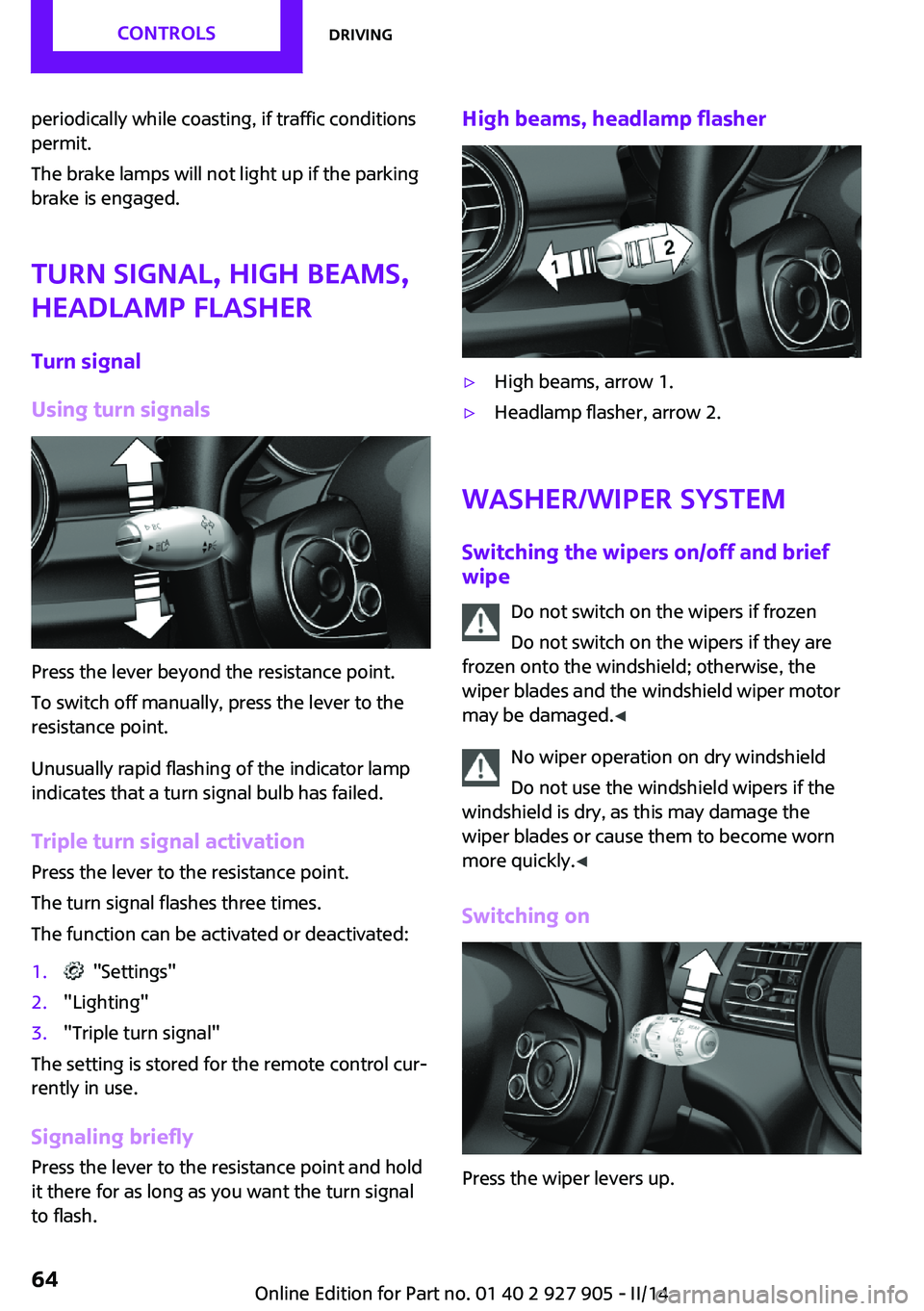
Press the lever beyond the resistance point.
To switch off manually, press the lever to the
resistance point.
Unusually rapid flashing of the indicator lamp
indicates that a turn signal bulb has failed.
Triple turn signal activation Press the lever to the resistance point.
The turn signal flashes three times.
The function can be activated or deactivated:
1. "Settings"2."Lighting"3."Triple turn signal"
The setting is stored for the remote control cur‐
rently in use.
Signaling briefly Press the lever to the resistance point and hold
it there for as long as you want the turn signal
to flash.
High beams, headlamp flasher▷High beams, arrow 1.▷Headlamp flasher, arrow 2.
Washer/wiper system
Switching the wipers on/off and brief
wipe
Do not switch on the wipers if frozen
Do not switch on the wipers if they are
frozen onto the windshield; otherwise, the
wiper blades and the windshield wiper motor
may be damaged. ◀
No wiper operation on dry windshield
Do not use the windshield wipers if the
windshield is dry, as this may damage the
wiper blades or cause them to become worn
more quickly. ◀
Switching on
Press the wiper levers up.
Seite 64CONTROLSDriving64
Online Edition for Part no. 01 40 2 927 905 - II/14
Page 72 of 230

Electronic displays1Driver assistance systems
Messages, e.g. Check Control
Time 75
External temperature 75
Selection lists 78
Miles/trip miles 74Computer 792Selector lever position display 67
Gear shift indicator 763Driving Dynamics Control 108
StatusCheck Control
The concept
The Check Control system monitors functions in
the vehicle and notifies you of malfunctions in the monitored systems.
A Check Control message is displayed as a com‐
bination of indicator or warning lamps and text
messages in the instrument cluster and in the
Head-up Display.
In addition, an acoustic signal may be output
and a text message may appear on the Control Display.Indicator/warning lamps
The indicator and warning lamps can light up in
a variety of combinations and colors.
Several of the lamps are checked for proper
functioning and light up temporarily when the
engine is started or the ignition is switched on.
Overview: indicator/warning lampsSymbolFunction or systemTurn signalFront fog lampsSeite 72CONTROLSDisplays72
Online Edition for Part no. 01 40 2 927 905 - II/14
Page 74 of 230

Hiding Check Control messages
Press the onboard computer button on the turn
signal lever.
▷Some Check Control messages are dis‐
played continuously and are not cleared
until the malfunction is eliminated. If sev‐
eral malfunctions occur at once, the mes‐
sages are displayed consecutively.
These messages can be hidden for approx.
8 seconds. After this time, they are dis‐
played again automatically.▷Other Check Control messages are hidden
automatically after approx. 20 seconds.
They are stored and can be displayed again
later.
Displaying stored Check Control
messages
1. "Vehicle Info"2."Vehicle status"3. "Check Control"4.Select the text message.
Messages after trip completion
Special messages that are displayed during
driving are displayed again after the ignition is
switched off.
Fuel gauge
The vehicle inclination may
cause the display to vary.
The arrow beside the fuel pump
symbol shows which side of the
vehicle the fuel filler flap is on.
Hints on refueling, refer to page 164.
Tachometer
Always avoid engine speeds in the red warning
field. In this range, the fuel supply is interrupted
to protect the engine.
Engine oil temperature If the engine oil along with the engine becomes
too hot, a Check Control message is displayed.
Coolant temperature If the coolant along with the engine becomes
too hot, a Check Control message is displayed.
Check the coolant level, refer to page 185.
Odometer and trip odom‐
eter
The concept
Odometer and trip odometer are displayed in
the instrument cluster.
Resetting the trip odometer Press the knob.▷The odometer is displayed
when the ignition is switched
off.Seite 74CONTROLSDisplays74
Online Edition for Part no. 01 40 2 927 905 - II/14
Page 79 of 230

Activating a list and adjusting the
settingButton the steering wheelFunctionActivate the corre‐
sponding list, and se‐
lect the desired set‐
ting.Confirm the selection.
Computer
Calling up information on the info
display
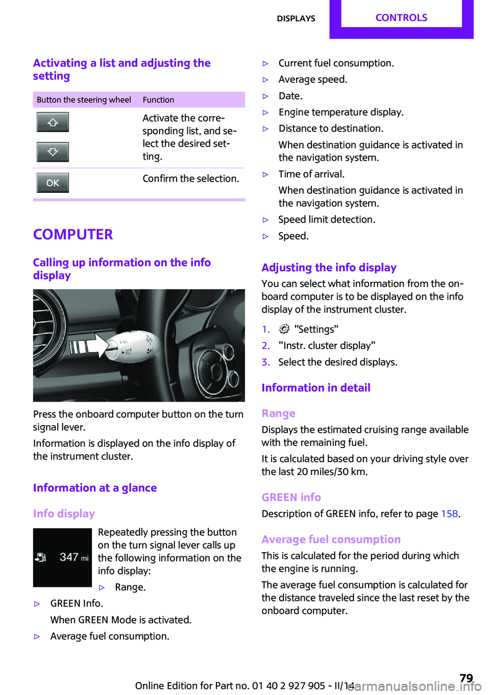
Press the onboard computer button on the turn
signal lever.
Information is displayed on the info display of
the instrument cluster.
Information at a glance
Info display Repeatedly pressing the button
on the turn signal lever calls up
the following information on the
info display:
▷Range.▷GREEN Info.
When GREEN Mode is activated.▷Average fuel consumption.▷Current fuel consumption.▷Average speed.▷Date.▷Engine temperature display.▷Distance to destination.
When destination guidance is activated in
the navigation system.▷Time of arrival.
When destination guidance is activated in
the navigation system.▷Speed limit detection.▷Speed.
Adjusting the info display
You can select what information from the on‐
board computer is to be displayed on the info
display of the instrument cluster.
1. "Settings"2."Instr. cluster display"3.Select the desired displays.
Information in detail
Range
Displays the estimated cruising range available
with the remaining fuel.
It is calculated based on your driving style over
the last 20 miles/30 km.
GREEN info Description of GREEN info, refer to page 158.
Average fuel consumption
This is calculated for the period during which
the engine is running.
The average fuel consumption is calculated for
the distance traveled since the last reset by the
onboard computer.
Seite 79DisplaysCONTROLS79
Online Edition for Part no. 01 40 2 927 905 - II/14
Page 80 of 230

Average speed
Periods in which the vehicle is parked with the
engine manually stopped are not included in
the calculation of the average speed.
Resetting average valuesPress and hold the onboard computer button
on the turn signal lever.
Distance to destination The distance remaining to the destination is
displayed if a destination is entered in the navi‐
gation system before the trip is started.
The distance to the destination is adopted au‐
tomatically.
Time of arrival The estimated time of arrival is displayed if a
destination is entered in the navigation system
before the trip is started.
The time must be correctly set.
Speed limit detection
Description of the speed limit detection, refer
to page 77, function.
Trip computer
The vehicle features two types of computer.▷"Onboard info": the values can be reset as
often as necessary.▷"Trip computer": the values provide an
overview of the current trip.
Resetting the trip computer
1. "Vehicle Info"2."Trip computer"3."Reset": all values are reset.
"Automatically reset": all values are reset
approx. 4 hours after the vehicle comes to
a standstill.Display on the Control Display
Display the onboard computer or trip computer
on the Control Display.1. "Vehicle Info"2."Onboard info" or "Trip computer"
Resetting the fuel consumption and
speed
1. "Vehicle Info"2."Onboard info"3."Consumpt." or "Speed"4."Yes"
Driving Excitement
The concept
On the Control Display, sport instruments can
be displayed, and the vehicle condition can be
checked before the use of the SPORT program.
Sport instruments On the Control Display, values for power and
torque are displayed.
Displaying sport instruments
Via onboard monitor:
1. "Vehicle Info"2."Driving Excitement"3. "Sports instruments"
Via the Driving Dynamics Control
1.Activating SPORT.2. "Driving Excitement"3. "Sports instruments"
Vehicle state
The following vehicle and surrounding area
data are automatically checked and evaluated
in succession:
▷Range.Seite 80CONTROLSDisplays80
Online Edition for Part no. 01 40 2 927 905 - II/14
Page 88 of 230

Cornering light is disrupted or failed. Have the
system checked as soon as possible.
High-beam Assistant The concept
When the low beams are switched on, this sys‐
tem automatically switches the high beams on
and off. The procedure is controlled by a sensor
on the front of the interior rearview mirror. The
assistant ensures that the high beams are
switched on whenever the traffic situation al‐
lows. The driver can intervene at any time and
switch the high beams on and off as usual.
Activating
The High-beam Assistant can be activated
when the low beams are switched on.
1.Turn the light switch to or .2.Press the button on the turn signal lever,
arrow.
The indicator lamp in the instrument
cluster lights up.
When the low beams are on, the lights are au‐
tomatically brightened or dimmed.
The system responds to light from oncoming
traffic and traffic driving ahead of you, and to
adequate illumination, e.g., in towns and cities.
The blue indicator lamp in the instru‐
ment cluster lights up when the system
switches on the high beams.
Switching the high beams on and off
manually▷High beams on, arrow 1.▷High beams off/headlamp flasher, arrow 2.
The High-beam Assistant can be switched off
when manually adjusting the light. To reacti‐
vate the High-beam Assistant, press the button
on the turn signal lever.
System limits Personal responsibility
The high-beam assistant cannot serve as
a substitute for the driver's personal judgment
of when to use the high beams. Therefore,
manually switch off the high beams in situa‐
tions where this is required to avoid a safety
risk. ◀
The system is not fully functional in situations
such as the following, and driver intervention
may be necessary:
▷In very unfavorable weather conditions,
such as fog or heavy precipitation.▷In detecting poorly-lit road users, such as
pedestrians, cyclists, horseback riders and
wagons; when driving close to train or ship
traffic; and at animal crossings.▷In tight curves, on hilltops or in depressions,
in cross traffic or half-obscured oncoming
traffic on freeways.▷In poorly-lit towns and cities and in the
presence of highly reflective signs.▷At low speeds.Seite 88CONTROLSLamps88
Online Edition for Part no. 01 40 2 927 905 - II/14
Page 123 of 230

This system assists the driver in parking parallel
to the road.
Ultrasound sensors measure parking spaces on
both sides of the vehicle.
The parking assistant calculates the best possi‐
ble parking line and takes control of steering
during the parking procedure.
When parking, also take note of the visual and
acoustic information issued by the PDC, the
parking assistant and, where applicable, the
rearview camera, and react accordingly.
A component of the parking assistant is the
PDC Park Distance Control, refer to page 118.
Hints Personal responsibility
Even an active system does not relieve
the driver from personal responsibility for the
driving process.
Because of technical system limits, the system
cannot independently react appropriately in all
traffic situations.
Continuously and attentively monitor the driv‐
ing process, the area surrounding the vehicle
and the traffic situation, and actively intervene
when required, otherwise, there is a risk of an
accident. ◀
Changes to the parking space
Changes to the parking space after it was
measured are not taken into account by the
system.
Therefore, always be alert and ready to inter‐
vene; otherwise, there is the danger of an acci‐
dent occurring. ◀
Transporting loads
Loads that extend beyond the perimeter
of the vehicle are not taken into account by the
system during the parking procedure.
Therefore, always be alert and ready to inter‐
vene; otherwise, there is the danger of an acci‐
dent occurring. ◀Curbs
The parking assistant may steer the vehi‐
cle over or onto curbs.
Therefore, always be alert and ready to inter‐
vene; otherwise, the wheels, tires, or the vehi‐
cle may become damaged. ◀
An engine that has been switched off by the
Auto Start Stop function is restarted automati‐
cally when the parking assistant is activated.
Requirements
For measuring parking spaces▷Maximum speed while driving forward ap‐
prox. 22 mph/35 km/h.▷Maximum distance to row of parked vehi‐
cles: 5 ft/1.5 m.
Suitable parking space
▷Gaps behind an object that have a min.
length of 5 ft/1.5 m.▷Gap between two objects with a minimum
length of approx. 5 ft/1.5 m.▷Min. length of gap between two objects:
your vehicle's length plus approx.
3.3 ft/1.0 m.▷Minimum depth: approx. 5 ft/1.5 m.
For parking procedure
▷Doors and tailgate closed.▷Parking brake released.▷When parking in parking spaces on the
driver's side, the corresponding turn signal
must be set.Seite 123Driving comfortCONTROLS123
Online Edition for Part no. 01 40 2 927 905 - II/14
Page 135 of 230

4.Likewise, press and hold the button of the
desired function on the hand-held trans‐
mitter.5.Release both buttons as soon as the interior
rearview mirror LED flashes more rapidly.
When the LED is flashing faster, this indi‐
cates that the button on the interior rear‐
view mirror has been programmed. The
system can then be controlled by the but‐
ton on the interior rearview mirror.
If the LED does not flash faster after at least
60 seconds, change the distance and re‐
peat the step. Several more attempts at dif‐
ferent distances may be necessary. Wait at
least 15 seconds between attempts.
Canada: if programming with the hand-
held transmitter was interrupted, hold
down the interior rearview mirror button
and repeatedly press and release the hand-
held transmitter button for 2 seconds.
Controls
Before operation
Before operating a system using the
integrated universal remote control, ensure
that there are no people, animals, or objects
within the range of movement of the remote-
controlled system; otherwise, there is a risk of
injury or damage.
Also follow the safety instructions of the hand- held transmitter. ◀
The system, such as the garage door, can be
operated using the button on the interior rear‐
view mirror while the engine is running or
when the ignition is started. To do this, hold down the button within receiving range of the
system until the function is activated. The inte‐
rior rearview mirror LED stays lit while the wire‐
less signal is being transmitted.
Deleting stored functions
Press and hold the left and right button on the
interior rearview mirror simultaneously for ap‐
proximately 20 seconds until the LED flashes
rapidly. All stored functions are deleted. The
functions cannot be deleted individually.
Digital compass
At a glance1Control button2Mirror display
Mirror display The point of the compass is displayed in the
mirror when driving straight.
Operating concept Various functions can be called up by pressing
the control button with a pointed object, such
as the tip of a ballpoint pen or similar object.
The following setting options are displayed in
succession, depending on how long the control
button is pressed:
▷Pressed briefly: turns display on/off.▷3 to 6 seconds: compass zone setting.▷6 to 9 seconds: compass calibration.▷9 to 12 seconds: left/right-hand steering
setting.▷12 to 15 seconds: language setting.
Setting the compass zones
Sets the particular compass zones on the vehi‐
cle so that the compass operates correctly; re‐
fer to World map with compass zones.
Seite 135Interior equipmentCONTROLS135
Online Edition for Part no. 01 40 2 927 905 - II/14