ESP MINI Countryman 2011 Owner's Manual
[x] Cancel search | Manufacturer: MINI, Model Year: 2011, Model line: Countryman, Model: MINI Countryman 2011Pages: 196, PDF Size: 3.06 MB
Page 15 of 196
CockpitAT A GLANCE
13
Indicator and warning
lamps
The concept
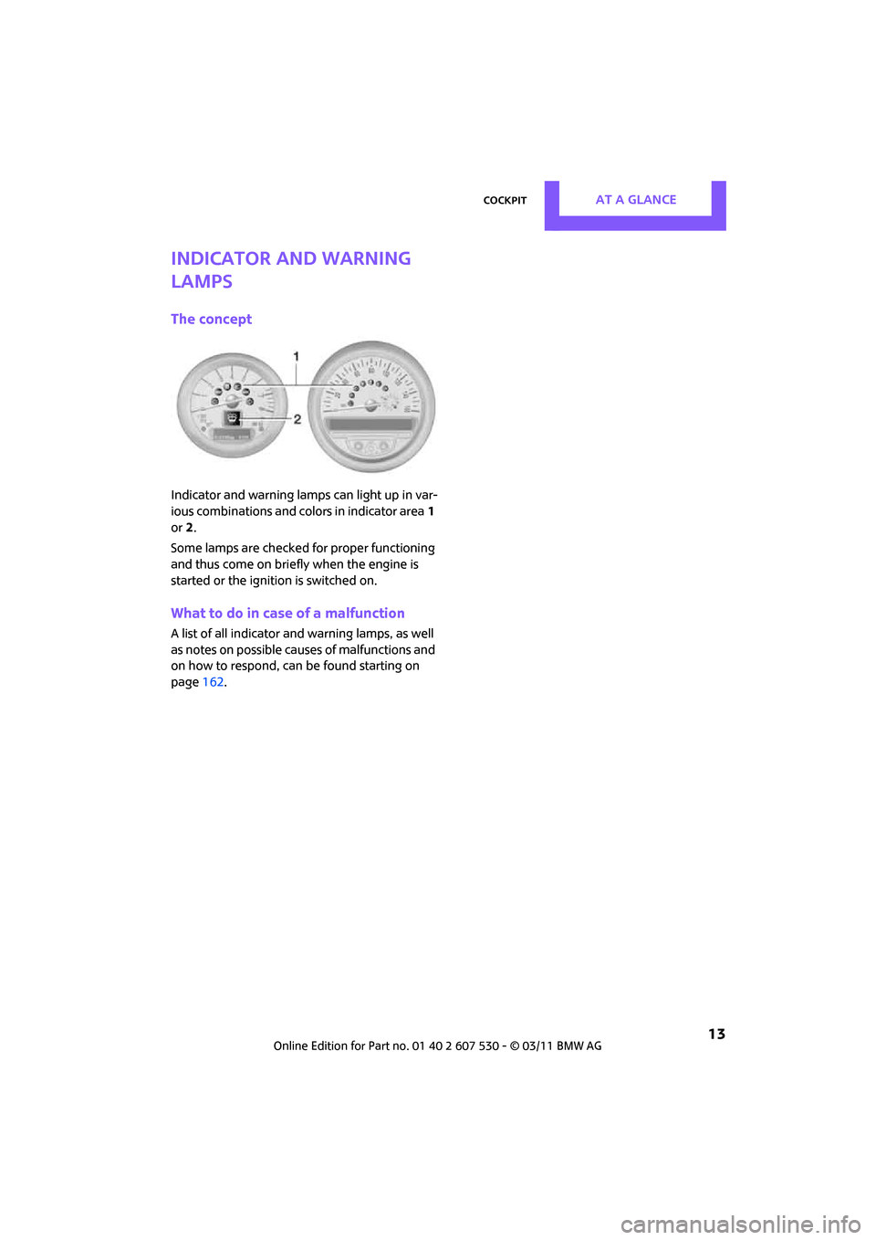
Indicator and warning lamps can light up in var-
ious combinations and colors in indicator area1
or 2.
Some lamps are checked for proper functioning
and thus come on briefly when the engine is
started or the ignition is switched on.
What to do in case of a malfunction
A list of all indicator and warning lamps, as well
as notes on possible caus es of malfunctions and
on how to respond, can be found starting on
page 162.
Page 22 of 196
ControlsOpening and closing
20
Opening and closing
Keys/remote controls
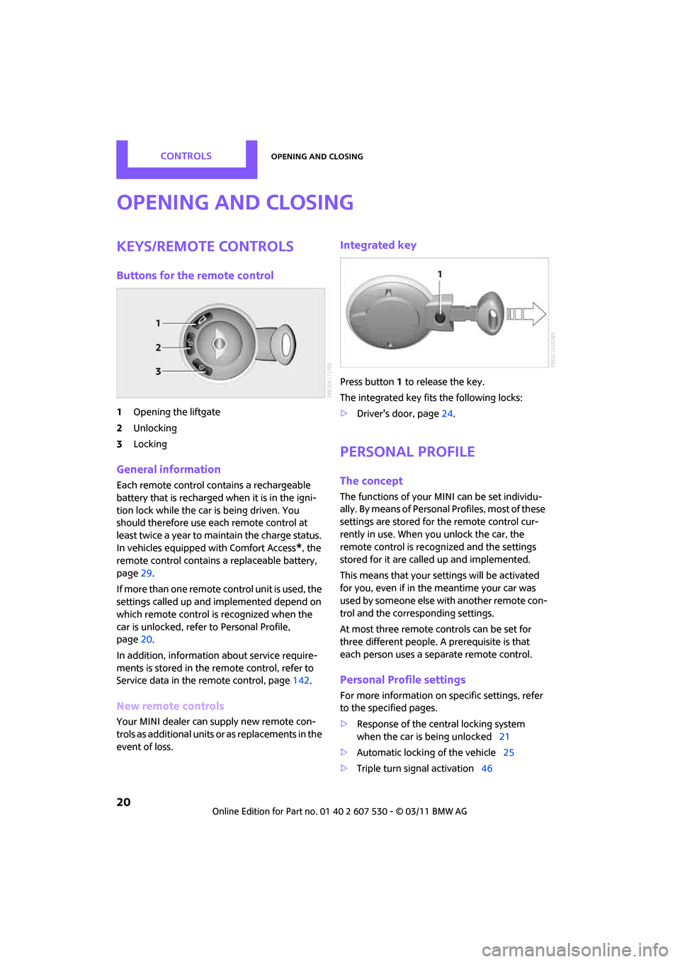
Buttons for the remote control
1Opening the liftgate
2 Unlocking
3 Locking
General information
Each remote control co ntains a rechargeable
battery that is recharged when it is in the igni-
tion lock while the car is being driven. You
should therefore use each remote control at
least twice a year to maintain the charge status.
In vehicles equipped with Comfort Access
*, the
remote control contains a replaceable battery,
page 29.
If more than one remote control unit is used, the
settings called up and implemented depend on
which remote control is recognized when the
car is unlocked, refer to Personal Profile,
page 20.
In addition, information about service require-
ments is stored in the remote control, refer to
Service data in the remote control, page 142.
New remote controls
Your MINI dealer can supply new remote con-
trols as additional units or as replacements in the
event of loss.
Integrated key
Press button1 to release the key.
The integrated key fits the following locks:
> Driver's door, page 24.
Personal Profile
The concept
The functions of your MINI can be set individu-
ally. By means of Personal Profiles, most of these
settings are stored for the remote control cur-
rently in use. When you unlock the car, the
remote control is recognized and the settings
stored for it are called up and implemented.
This means that your settings will be activated
for you, even if in the meantime your car was
used by someone else with another remote con-
trol and the corresponding settings.
At most three remote co ntrols can be set for
three different people. A prerequisite is that
each person uses a se parate remote control.
Personal Profile settings
For more information on specific settings, refer
to the specified pages.
> Response of the central locking system
when the car is being unlocked 21
> Automatic locking of the vehicle 25
> Triple turn signal activation 46
Page 35 of 196
AdjustmentsControls
33
Seats
Note before adjusting
Never attempt to adjust your seat while
the vehicle is moving. The seat could
respond with unexpected movement, and the
ensuing loss of vehicle control could lead to an
accident.
On the front passenger seat as well, do not
incline the backrest too far to the rear while the
vehicle is being driven; otherwise, there is a dan-
ger in the event of an a ccident of sliding under
the safety belt, eliminat ing the protection nor-
mally provided by the belt. <
Comply with the instruct ions on head restraint
height on page 34 and on damaged safety belts
on page 36.
Seat adjustment, front
Observe the instructions on page 33 to
ensure the best possible personal protec-
tion. <
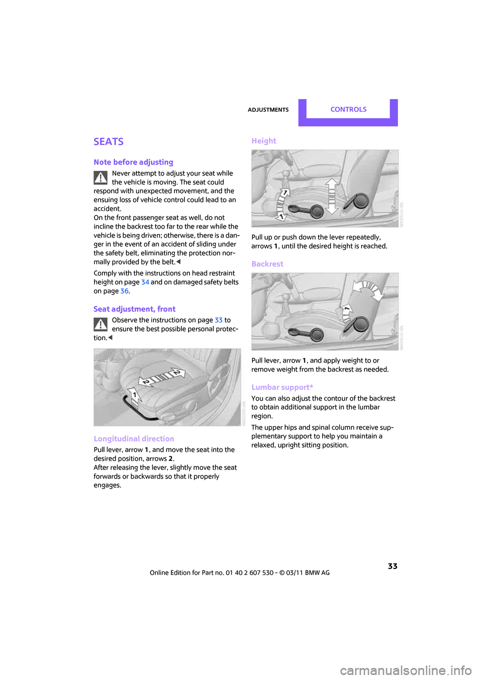
Longitudinal direction
Pull lever, arrow 1, and move the seat into the
desired position, arrows 2.
After releasing the lever, slightly move the seat
forwards or backwards so that it properly
engages.
Height
Pull up or push down the lever repeatedly,
arrows 1, until the desired height is reached.
Backrest
Pull lever, arrow 1, and apply weight to or
remove weight from the backrest as needed.
Lumbar support*
You can also adjust the contour of the backrest
to obtain additional support in the lumbar
region.
The upper hips and spinal column receive sup-
plementary support to help you maintain a
relaxed, upright sitting position.
Page 40 of 196
ControlsTransporting children safely
38
Transporting children safely
The right place for
children
Do not leave children unattended in the
vehicle; otherwise, they could endanger
themselves and/or other persons by opening the
doors, for example. <
Children should always sit in the rear
Accident research has shown that the safest
place for children is on the rear seat.
Only transport children under the age of
13 or smaller than 5 ft/150 cm in the rear
in a child restraint system suitable for their age,
weight and size. Otherwise, there is an
increased risk of injury in the event of an acci-
dent. <
Children 13 years of age or older must be buck-
led in with a safety belt as soon as there no
longer is any child restraint system that is appro-
priate for their age, size and weight.
Exception for front passenger seat
Front passenger airbags
Should it be necessary to use a child
restraint system on the front passenger
seat, the front and side airbags must be deacti-
vated. Otherwise, there is an increased risk of
injury to the child if th e airbags deploy, even if
the child is seated in a child restraint system.<
For more information on automatic deactivation
of the front passenger airbags, refer to page 68.
Child restraint systems,
installation
Before installing a child restraint system on the
rear seats, move the seat as far back as possible. After the child restr
aint system has been
installed on the respecti ve rear seat, move the
backrest forward so that the it rests lightly
against the child restrain t system, refer to Rear
seat backrests on page 92.
Observe the child restraint system manu-
facturer's instructions when selecting,
installing and using child restraint systems. Oth-
erwise, the protective effect may be dimin-
ished. <
On the front passenger seat
After installing a chil d restraint system on
the front passenger se at, make sure that
the front, side, and knee airbags for the front
passenger are deactivated; otherwise, there is
an increased risk of inju ry if the airbags deploy.<
Seat position
Before installing a child restraint system, move
the front passenger seat as far back and up
* as
possible to obtain the be st possible position for
the belt. Do not change the seat position after
this.
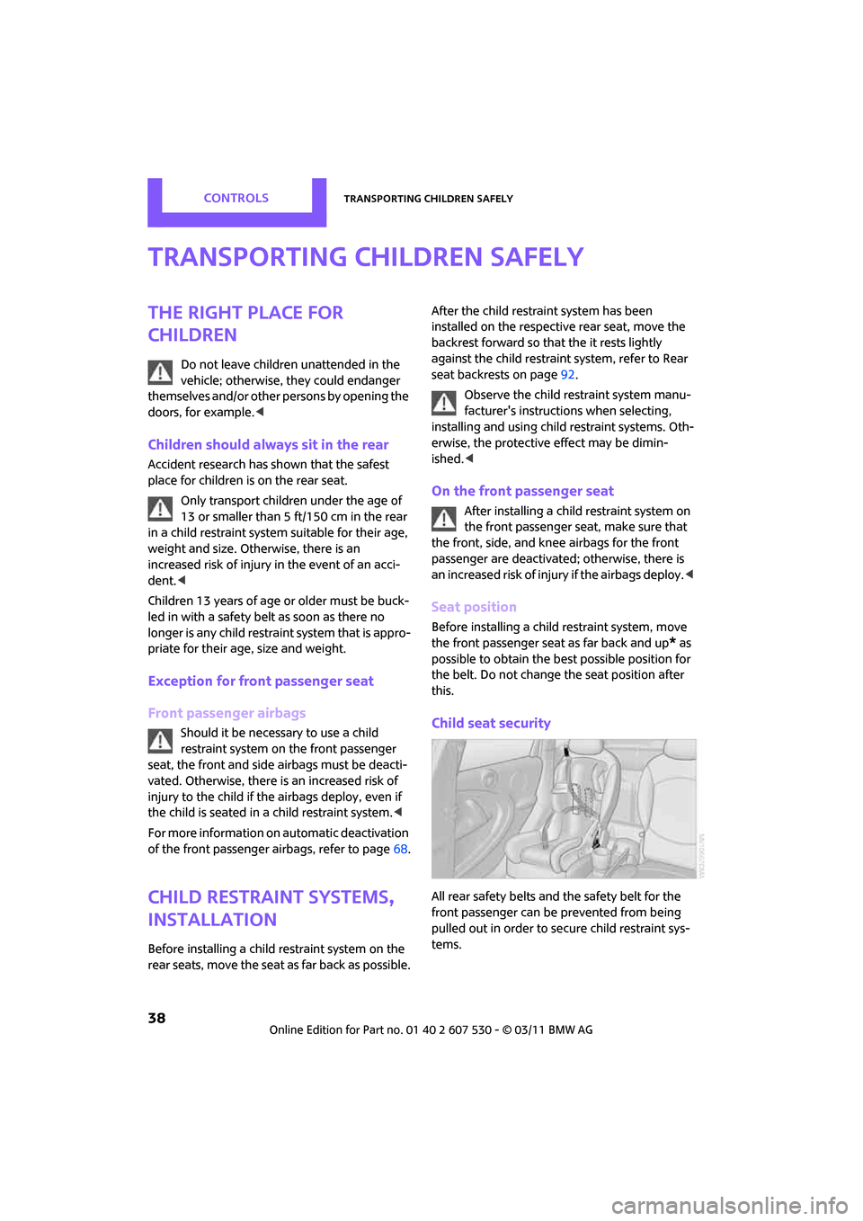
Child seat security
All rear safety belts and the safety belt for the
front passenger can be prevented from being
pulled out in order to se cure child restraint sys-
tems.
Page 53 of 196
Controls overviewControls
51
Controls overview
Tachometer
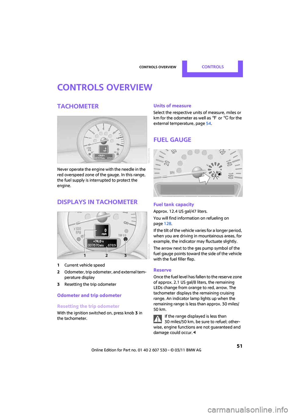
Never operate the engine with the needle in the
red overspeed zone of the gauge. In this range,
the fuel supply is interrupted to protect the
engine.
Displays in tachometer
1Current vehicle speed
2 Odometer, trip odometer, and external tem-
perature display
3 Resetting the trip odometer
Odometer and trip odometer
Resetting the trip odometer
With the ignition switched on, press knob 3 in
the tachometer.
Units of measure
Select the respective units of measure, miles or
km for the odometer as well as 7 or 6 for the
external temperature, page 54.
Fuel gauge
Fuel tank capacity
Approx. 12.4USgal/47liters.
You will find information on refueling on
page 128.
If the tilt of the vehicle varies for a longer period,
when you are driving in mountainous areas, for
example, the indicator may fluctuate slightly.
The arrow next to the gas pump symbol of the
fuel gauge points toward the side of the vehicle
with the fuel filler flap.
Reserve
Once the fuel level has fallen to the reserve zone
of approx. 2.1 US gal/8 liters, the remaining
LEDs change from orange to red, arrow. The
tachometer
displays the remaining cruising
range. An indicator lamp lights up when the
remaining range is less than approx. 30 miles/
50 km.
If the range displayed is less than
30 miles/50 km, be sure to refuel; other-
wise, engine functions are not guaranteed and
damage could occur.<
Page 54 of 196

ControlsControls overview
52
Computer*
Displays in the tachometer
Press the button in the turn signal lever repeat-
edly to call up various items of information.
The following items of information are displayed
in the order listed:
> Cruising range
> Average fuel consumption
> Current fuel consumption
> Average speed
> Outside temperature display
To set the corresponding units of measure, refer
to Formats and units of measure on page 54.
Cruising range
Displays the estimated cruising range available
with the remaining fuel. The range is calculated
on the basis of the way the car has been driven
over the last 18 miles/30 km and the amount of
fuel currently in the tank.
If the range displayed is less than
30 miles/50 km, be sure to refuel; other-
wise, engine functions are not guaranteed and
damage could occur. <
Average fuel consumption
Calculated for the time the engine has been run-
ning.
To reset average fuel consumption: press the
button in the turn signal lever for approx.
2seconds.
Current fuel consumption
Displays the current fuel consumption to allow
you to see whether your current driving style is
conducive to fuel economy with minimum
exhaust emissions.
Average speed
Periods with the vehicle parked and the engine
switched off are not includ ed in the calculations
of average speed.
To reset average speed: press the button in the
turn signal lever for approx. 2 seconds.
External temperature warning
When the displayed temperature sinks to
approx. +37 7/+3 6, a signal sounds and a
warning lamp lights up. There is an increased
risk of black ice.
Even at temperatures above +37 7/+3 6
ice can form. Therefore, drive carefully,
e.g. on bridges and sect ions of road in the
shade; otherwise, there is an increased accident
risk. <
Settings and information
Operating principle
Certain settings and information are only avail-
able when the ignition is switched on, the vehi-
cle is at a standstill and the doors are closed.
Page 55 of 196
Controls overviewControls
53
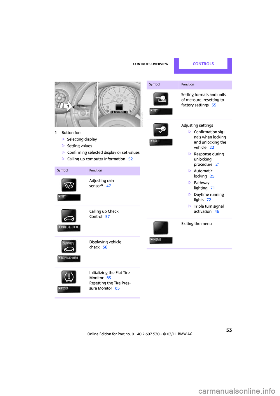
1Button for:
>Selecting display
> Setting values
> Confirming selected display or set values
> Calling up computer information 52
SymbolFunction
Adjusting rain
sensor
*47
Calling up Check
Control 57
Displaying vehicle
check 58
Initializing the Flat Tire
Monitor 63
Resetting the Tire Pres-
sure Monitor 65
Setting formats and units
of measure, resetting to
factory settings 55
Adjusting settings >Confirmation sig-
nals when locking
and unlocking the
vehicle 22
> Response during
unlocking
procedure 21
> Automatic
locking 25
> Pathway
lighting 71
> Daytime running
lights 72
> Triple turn signal
activation 46
Exiting the menu
SymbolFunction
Page 58 of 196
ControlsControls overview
56
The extent of service work required can be
read out from the remote control by your
MINI dealer. <
Displaying vehicle check
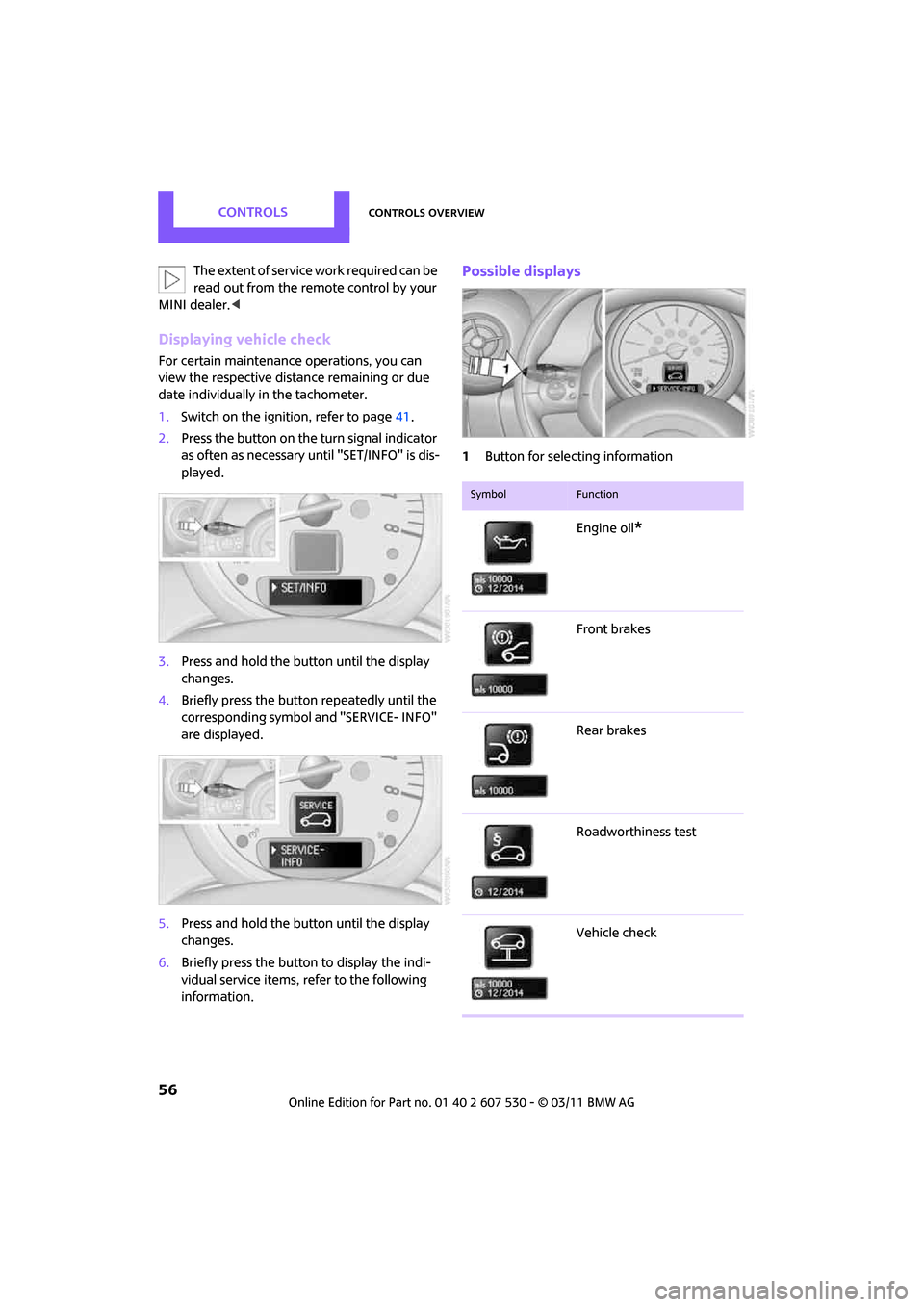
For certain maintenance operations, you can
view the respective distance remaining or due
date individually in the tachometer.
1.Switch on the ignition, refer to page 41.
2. Press the button on the turn signal indicator
as often as necessary until "SET/INFO" is dis-
played.
3. Press and hold the button until the display
changes.
4. Briefly press the button repeatedly until the
corresponding symbol and "SERVICE- INFO"
are displayed.
5. Press and hold the button until the display
changes.
6. Briefly press the button to display the indi-
vidual service items, refer to the following
information.
Possible displays
1Button for selecting information
SymbolFunction
Engine oil*
Front brakes
Rear brakes
Roadworthiness test
Vehicle check
Page 59 of 196

Controls overviewControls
57
More information on the MINI Maintenance Sys-
tem can be found on page 142.
Clock
Setting the time
Radio MINI Boost CD:
1.Press the MENU button.
2. Press the button.
3. Press the button.
4. Select the desired menu item "FORMAT",
"STD" or "MIN" and press the respective but-
ton.
5. Turn the button on the right to set values.
6. Press the button on the right to store values.
7. Press the button to exit setting
values.
Date
Setting date
Radio MINI Boost CD:
1. Press the MENU button.
2. Press the button.
3. Press the button.
4. Select the desired menu item "TT", "MM" or
"JJ".
5. Turn the button on the right to set values.
6. Press the button on the right to store values.
7. Press the button to exit setting
values.
Check Control
The concept
The Check Control monitors vehicle functions
and alerts you to any ma lfunctions in the sys-
tems monitored. Check Control messages
involve indicator or warning lamps in the dis-
plays and, in some circumstances, an acoustic
signal.
Indicator and warning lamps can light up in var-
ious combinations and colors in the indicator
areas 1 and 2.
Brake fluid
Exit display
54
Next setting or item of
information 54
SymbolFunction
Page 60 of 196
ControlsControls overview
58
What to do in case of a malfunction
The meaning of each lamp in the event of a mal-
function and tips on how to respond are listed
starting on page162.
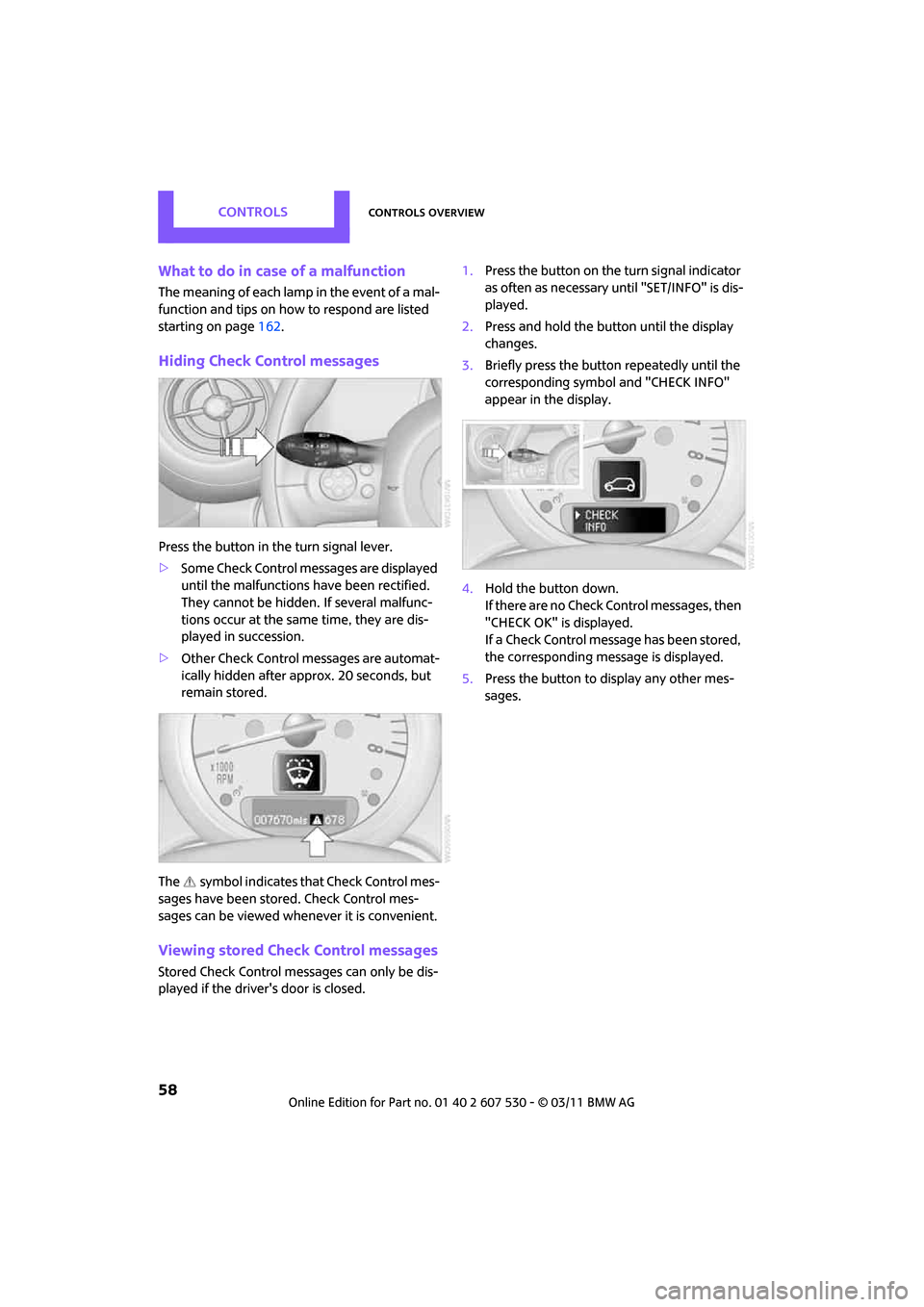
Hiding Check Control messages
Press the button in th e turn signal lever.
> Some Check Control me ssages are displayed
until the malfunctions have been rectified.
They cannot be hidden. If several malfunc-
tions occur at the same time, they are dis-
played in succession.
> Other Check Control messages are automat-
ically hidden after approx. 20 seconds, but
remain stored.
The symbol indicates that Check Control mes-
sages have been stor ed. Check Control mes-
sages can be viewed whenever it is convenient.
Viewing stored Check Control messages
Stored Check Control me ssages can only be dis-
played if the driver's door is closed. 1.
Press the button on the turn signal indicator
as often as necessary until "SET/INFO" is dis-
played.
2. Press and hold the button until the display
changes.
3. Briefly press the button repeatedly until the
corresponding symbol and "CHECK INFO"
appear in the display.
4. Hold the button down.
If there are no Check Control messages, then
"CHECK OK" is displayed.
If a Check Control message has been stored,
the corresponding message is displayed.
5. Press the button to display any other mes-
sages.