display MINI Countryman 2015 Owner's Manual (Mini Connected)
[x] Cancel search | Manufacturer: MINI, Model Year: 2015, Model line: Countryman, Model: MINI Countryman 2015Pages: 283, PDF Size: 6.76 MB
Page 6 of 283
Addendum
“MINI recommends that you have the main-
tenance carried out by your service center.”
9. At page 207, under the heading “Software
applications,” the text of that section should
be disregarded and the following text read
in lieu thereof: “The manufacturer of your
vehicle recommends the use of MINI recom-
mended software; otherwise there may be
malfunctions in system operations.”
10. At page 216, under the heading “Pressure
specifications,” the sentence beginning,
“The inflation pressures apply to the tire si-
zes approved … .” should be disregarded.
11. At page 223, under the heading: “Approved
wheels and tires,” the term “Approved”
should be disregarded and in lieu thereof,
the term “Recommended” should be read in
its place. In addition, the text of that section
should be disregarded and the following
text should be read in lieu thereof:
The manufacturer of your vehicle strongly
suggests that you use wheels and tires that
have been recommended by the vehicle
manufacturer for your vehicle type; other-
wise, for example, despite having the same
official size ratings, variations can lead to
body contact and with it, the risk of severe
accidents.
The manufacturer of your vehicle does not
evaluate non-recommended wheels and ti-
res to determine if they are suitable for use
on your vehicle.
12. At page 229, under the heading “Hood,” the
sentence beginning, “If you are unfamiliar”
should be disregarded.
13. At page 233, under the heading: “Service
and Warranty Information Booklet for US
Models and Warranty and Service Guide
Booklet for Canadian Models,” the second
paragraph should be disregarded and the
following text read in lieu thereof:
The manufacturer of your vehicle recom-
mends that you have maintenance and re-
pair performed by your MINI dealer's service
center or another service center or repair
shop that employs trained personnel that
can perform maintenance and repair work
on your vehicle in accordance with MINI
specifications. The manufacturer of your ve-
hicle recommends that you maintain re-
cords of all maintenance and repair work
performed on your vehicle.
14. At page 243, under the “Battery replace-
ment” section, the text should be disregar-
ded and in lieu thereof the following text
should be read:
Use of recommended vehicle batteries
The manufacturer of your vehicle recom-
mends that you use vehicle batteries that it
has tested and recommends for use in your
vehicle; otherwise the vehicle could be da-
maged and systems or functions may not be
fully available.
After a battery replacement, the manufactu-
rer of your vehicle recommends that you
have the battery registered on your vehicle
by a service center to ensure that all comfort
functions are fully available, and that any
“check control” messages of these comfort
functions are no longer displayed.
Online Edition for Part no. 01 40 2 961 110 - II/15
Page 7 of 283
ContentsThe fastest way to find information on a partic‐
ular topic or item is by using the index, refer to
page 268.6Notes
AT A GLANCE
12Cockpit18Onboard monitor24Voice activation system
CONTROLS
30Opening and closing44Adjusting52Transporting children safely57Driving67Displays77Lamps81Safety92Driving stability control systems96Driving comfort99Climate105Interior equipment115Storage compartments
DRIVING TIPS
120Things to remember when driving124Loading128Saving fuel
NAVIGATION
132Navigation system134Destination entry143Destination guidance151What to do if...ENTERTAINMENT154Tone156Radio164CD/multimedia
COMMUNICATION
178Bluetooth hands-free system188Bluetooth mobile phone preparation
package199Office207MINI Connected
MOBILITY
212Refueling214Fuel216Wheels and tires228Engine compartment230Engine oil232Coolant233Maintenance235Replacing components245Breakdown assistance250Care
REFERENCE
258Technical data262Short commands for voice activation268Everything from A to Z
Online Edition for Part no. 01 40 2 961 110 - II/15
Page 8 of 283
NotesUsing this Owner's
Manual
The fastest way to find information on a partic‐
ular topic is by using the index.
An initial overview of the vehicle is provided in
the first chapter.
Additional sources of information
Should you have any questions, your service
center will be glad to advise you at any time.
Information on MINI, e.g., on technology, is
available on the Internet: www.mini.com
Information about MINI, e.g., on technology, is
available on the Internet: www.miniusa.com
Symbols
Indicates precautions that must be followed
precisely in order to avoid the possibility of
personal injury and serious damage to the
vehicle.
◄ Marks the end of a specific item of
information.
"..." Identifies Control Display texts used to
select individual functions.
›...‹ Verbal instructions to use with the voice
activation system.
››...‹‹ Identifies the answers generated by the
voice activation system.
Refers to measures that can be taken to
help protect the environment.
Symbols on vehicle components
Indicates that you should consult the
relevant section of this Owner's Manual for
information on a particular part or assembly.
Vehicle equipment
The manufacturer of your MINI is the Bayeri‐
sche Motoren Werke Aktiengesellschaft, BMW
AG.
This Owner's Manual describes all models, all
series equipment, as well as country-specific
and special equipment offered in the model
series. Therefore, this Owner's Manual also de‐
scribes and depicts equipment that may not be
contained in your vehicle because of the se‐
lected special equipment or country version, for
example.
This also applies to safety-related functions and
systems.
For options and equipment not described in
this Owner's Manual, please refer to the Sup‐
plementary Owner's Manuals.
Status of this Owner's
Manual at time of print‐
ing
The manufacturer of your vehicle pursues a
policy of constant development that is con‐
ceived to ensure that our vehicles continue to
embody the highest quality and safety stan‐
dards. In rare cases, therefore, the features de‐
scribed in this Owner's Manual may differ from
those in your vehicle.
For your own safety
Warranty
Your vehicle is technically configured for the
operating conditions and registration require‐
ments applying in the country of first delivery
— homologation. If your vehicle is to be oper‐
ated in a different country it might be neces‐Seite 6Notes6
Online Edition for Part no. 01 40 2 961 110 - II/15
Page 16 of 283
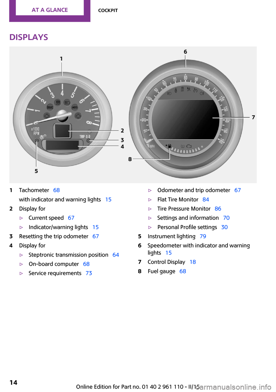
Displays1Tachometer 68
with indicator and warning lights 152Display for▷Current speed 67▷Indicator/warning lights 153Resetting the trip odometer 674Display for▷Steptronic transmission position 64▷On-board computer 68▷Service requirements 73▷Odometer and trip odometer 67▷Flat Tire Monitor 84▷Tire Pressure Monitor 86▷Settings and information 70▷Personal Profile settings 305Instrument lighting 796Speedometer with indicator and warning
lights 157Control Display 188Fuel gauge 68Seite 14AT A GLANCECockpit14
Online Edition for Part no. 01 40 2 961 110 - II/15
Page 17 of 283
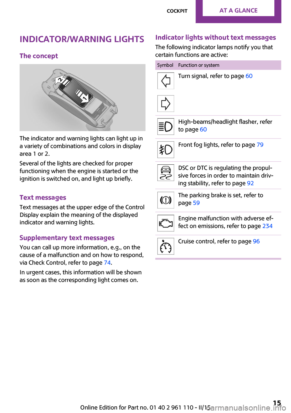
Indicator/warning lights
The concept
The indicator and warning lights can light up in
a variety of combinations and colors in display
area 1 or 2.
Several of the lights are checked for proper
functioning when the engine is started or the
ignition is switched on, and light up briefly.
Text messages
Text messages at the upper edge of the Control
Display explain the meaning of the displayed
indicator and warning lights.
Supplementary text messages
You can call up more information, e.g., on the
cause of a malfunction and on how to respond,
via Check Control, refer to page 74.
In urgent cases, this information will be shown
as soon as the corresponding light comes on.
Indicator lights without text messages
The following indicator lamps notify you that
certain functions are active:SymbolFunction or systemTurn signal, refer to page 60High-beams/headlight flasher, refer
to page 60Front fog lights, refer to page 79DSC or DTC is regulating the propul‐
sive forces in order to maintain driv‐
ing stability, refer to page 92The parking brake is set, refer to
page 59Engine malfunction with adverse ef‐
fect on emissions, refer to page 234Cruise control, refer to page 96Seite 15CockpitAT A GLANCE15
Online Edition for Part no. 01 40 2 961 110 - II/15
Page 18 of 283
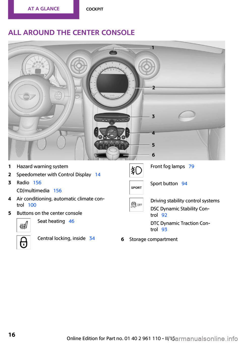
All around the center console1Hazard warning system2Speedometer with Control Display 143Radio 156
CD/multimedia 1564Air conditioning, automatic climate con‐
trol 1005Buttons on the center consoleSeat heating 46Central locking, inside 34Front fog lamps 79Sport button 94Driving stability control systems
DSC Dynamic Stability Con‐
trol 92
DTC Dynamic Traction Con‐
trol 936Storage compartmentSeite 16AT A GLANCECockpit16
Online Edition for Part no. 01 40 2 961 110 - II/15
Page 20 of 283
Onboard monitorVehicle equipmentThis chapter describes all series equipment as
well as country-specific and special equipment
offered for this model series. Therefore, it also
describes equipment that may not be found in
your vehicle, for instance due to the selected
special equipment or the country version. This
also applies to safety-related functions and sys‐
tems.
When using the features and systems described
here, adhere to local regulations.
The concept
The onboard monitor combines the functions
of a large number of different switches. Thus,
these functions can be operated from a central
location.
Using the onboard monitor during a trip
To avoid becoming distracted and posing
an unnecessary hazard to your vehicle's occu‐
pants and to other road users, never attempt to
use the controls or enter information unless
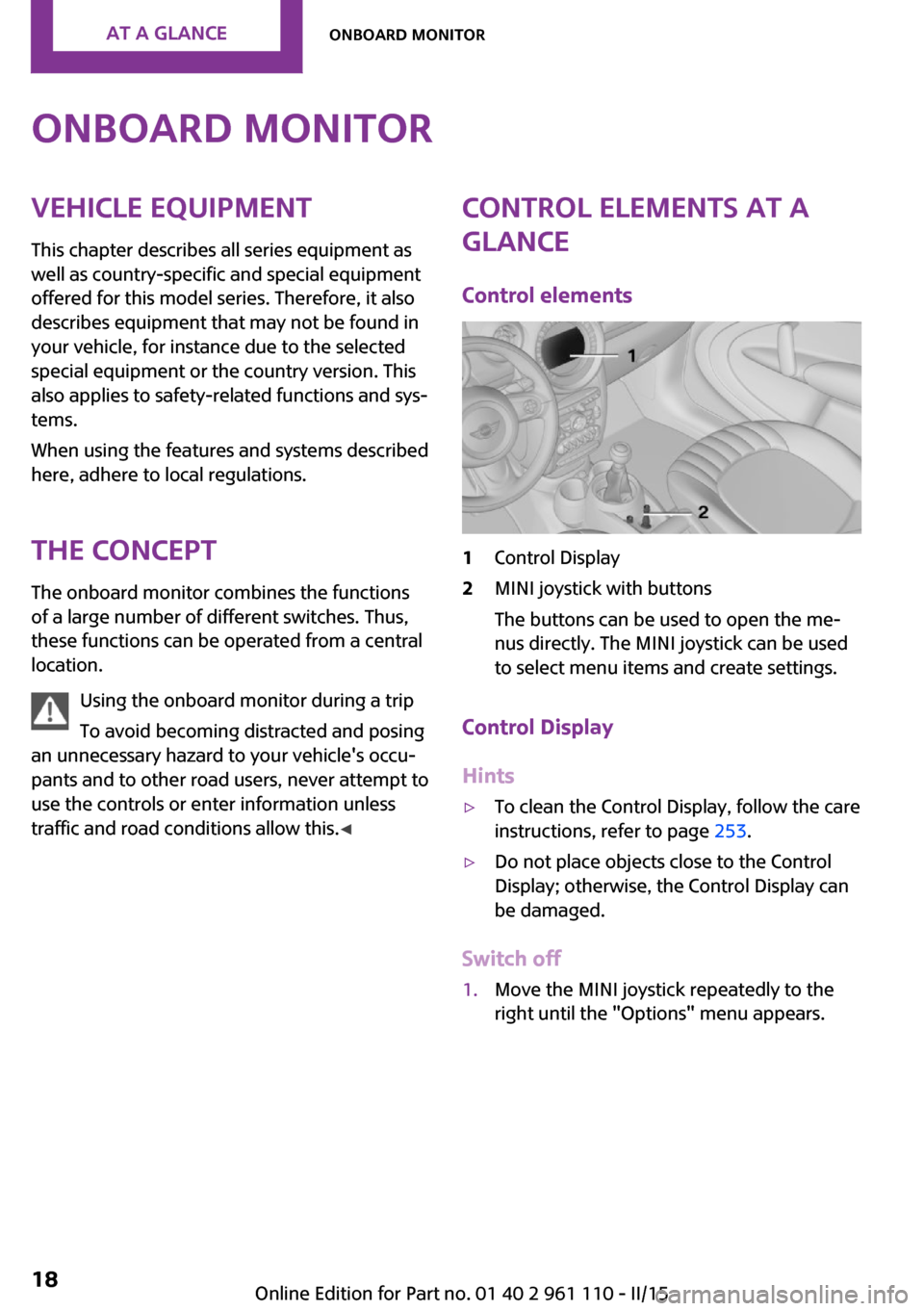
traffic and road conditions allow this. ◀Control elements at a
glance
Control elements1Control Display2MINI joystick with buttons
The buttons can be used to open the me‐
nus directly. The MINI joystick can be used
to select menu items and create settings.
Control Display
Hints
▷To clean the Control Display, follow the care
instructions, refer to page 253.▷Do not place objects close to the Control
Display; otherwise, the Control Display can
be damaged.
Switch off
1.Move the MINI joystick repeatedly to the
right until the "Options" menu appears.Seite 18AT A GLANCEOnboard monitor18
Online Edition for Part no. 01 40 2 961 110 - II/15
Page 21 of 283
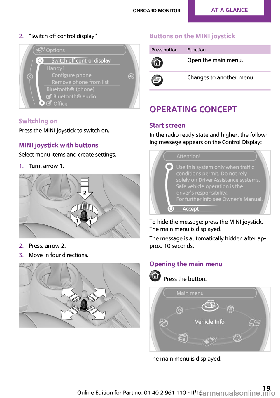
2."Switch off control display"
Switching on
Press the MINI joystick to switch on.
MINI joystick with buttonsSelect menu items and create settings.
1.Turn, arrow 1.2.Press, arrow 2.3.Move in four directions.Buttons on the MINI joystickPress buttonFunction
Open the main menu. Changes to another menu.
Operating concept
Start screen In the radio ready state and higher, the follow‐
ing message appears on the Control Display:
To hide the message: press the MINI joystick.
The main menu is displayed.
The message is automatically hidden after ap‐
prox. 10 seconds.
Opening the main menu
Press the button.
The main menu is displayed.
Seite 19Onboard monitorAT A GLANCE19
Online Edition for Part no. 01 40 2 961 110 - II/15
Page 22 of 283
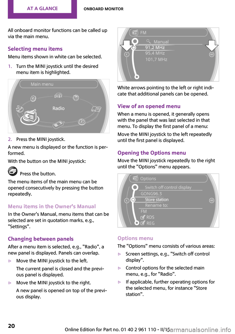
All onboard monitor functions can be called up
via the main menu.
Selecting menu items Menu items shown in white can be selected.1.Turn the MINI joystick until the desired
menu item is highlighted.2.Press the MINI joystick.
A new menu is displayed or the function is per‐
formed.
With the button on the MINI joystick:
Press the button.
The menu items of the main menu can be
opened consecutively by pressing the button
repeatedly.
Menu items in the Owner's Manual
In the Owner's Manual, menu items that can be
selected are set in quotation marks, e.g.,
"Settings".
Changing between panelsAfter a menu item is selected, e.g., "Radio", a
new panel is displayed. Panels can overlap.
▷Move the MINI joystick to the left.
The current panel is closed and the previ‐
ous panel is displayed.▷Move the MINI joystick to the right.
A new panel is opened on top of the previ‐
ous display.
White arrows pointing to the left or right indi‐
cate that additional panels can be opened.
View of an opened menu
When a menu is opened, it generally opens
with the panel that was last selected in that
menu. To display the first panel of a menu:
Move the MINI joystick to the left repeatedly
until the first panel is displayed.
Opening the Options menu Move the MINI joystick repeatedly to the right
until the "Options" menu appears.
Options menu
The "Options" menu consists of various areas:
▷Screen settings, e.g., "Switch off control
display".▷Control options for the selected main
menu, e.g., for "Radio".▷If applicable, further operating options for
the selected menu, for instance "Store
station".Seite 20AT A GLANCEOnboard monitor20
Online Edition for Part no. 01 40 2 961 110 - II/15
Page 23 of 283
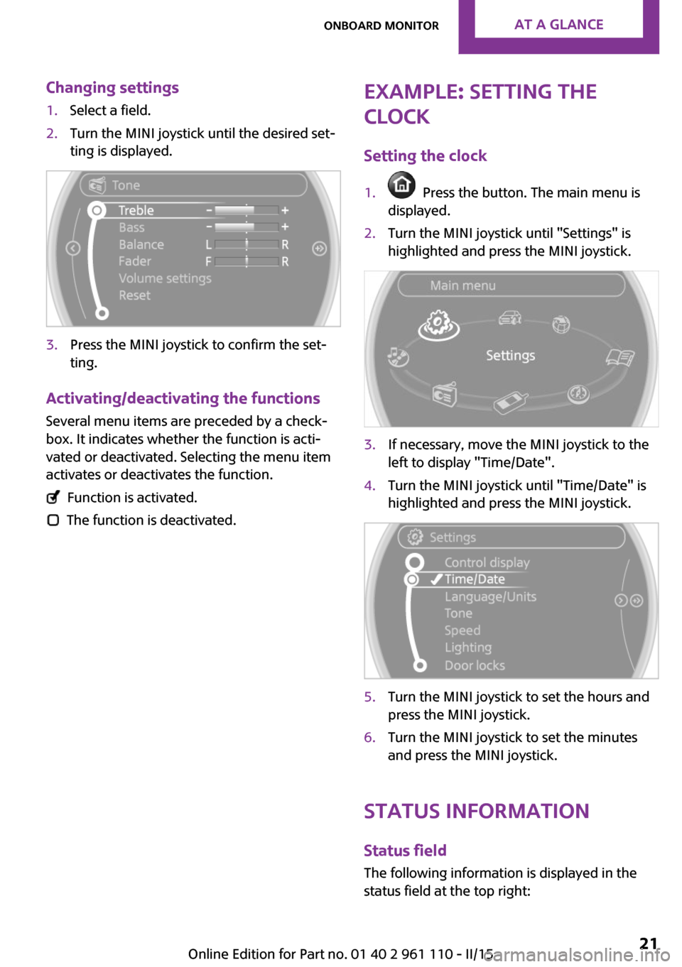
Changing settings1.Select a field.2.Turn the MINI joystick until the desired set‐
ting is displayed.3.Press the MINI joystick to confirm the set‐
ting.
Activating/deactivating the functions
Several menu items are preceded by a check‐box. It indicates whether the function is acti‐
vated or deactivated. Selecting the menu item
activates or deactivates the function.
Function is activated.
The function is deactivated.
Example: setting the
clock
Setting the clock1. Press the button. The main menu is
displayed.2.Turn the MINI joystick until "Settings" is
highlighted and press the MINI joystick.3.If necessary, move the MINI joystick to the
left to display "Time/Date".4.Turn the MINI joystick until "Time/Date" is
highlighted and press the MINI joystick.5.Turn the MINI joystick to set the hours and
press the MINI joystick.6.Turn the MINI joystick to set the minutes
and press the MINI joystick.
Status information
Status fieldThe following information is displayed in the
status field at the top right:
Seite 21Onboard monitorAT A GLANCE21
Online Edition for Part no. 01 40 2 961 110 - II/15