display MINI Countryman 2016 (Mini Connected) Service Manual
[x] Cancel search | Manufacturer: MINI, Model Year: 2016, Model line: Countryman, Model: MINI Countryman 2016Pages: 282, PDF Size: 6.79 MB
Page 94 of 282

Deactivating DSC
Press the switch until the DSC OFF indicator
lamp lights up in the speedometer and DSC OFF
appears in the tachometer. DSC is deactivated.
Intervening measures to stabilize the vehicle
and give it forward momentum are no longer
executed.
When driving with snow chains or to rock the
vehicle free of snow, it may be useful to deacti‐
vate DSC temporarily.
To increase vehicle stability, activate DSC again
as soon as possible.
Activating DSC
Press the switch again; the DSC indicator lamps
in the display elements go out.
Indicator/warning lights The indicator lamp in the tachometer
flashes: DSC is controlling the drive
forces and brake forces.
The indicator lamp lights up: DSC and DTC has
failed.
The indicator lamp in the speedometer
lights up and DSC OFF appears in the
tachometer.
DSC and DTC deactivated.
Dynamic Traction Con‐
trol DTC
The concept
The DTC system is a version of the DSC in which
forward momentum is optimized.
The system ensures maximum forward mo‐
mentum on special road conditions, e.g., unp‐
lowed snowy roads, but driving stability is lim‐
ited.
It is therefore necessary to drive with appropri‐
ate caution.
You may find it useful to briefly activate DTC
under the following special circumstances:
▷When driving in sand, on snowy inclines, in
slush, or on unplowed, snow-covered road
surfaces.▷When rocking a vehicle free or starting off
in deep snow, sand, or on loose ground.▷When driving with snow chains.Seite 94CONTROLSDriving stability control systems94
Online Edition for Part no. 01 40 2 964 459 - VI/15
Page 96 of 282
▷For Steptronic transmissions: more rapid
gear changes in the Sport program.
Activating the system
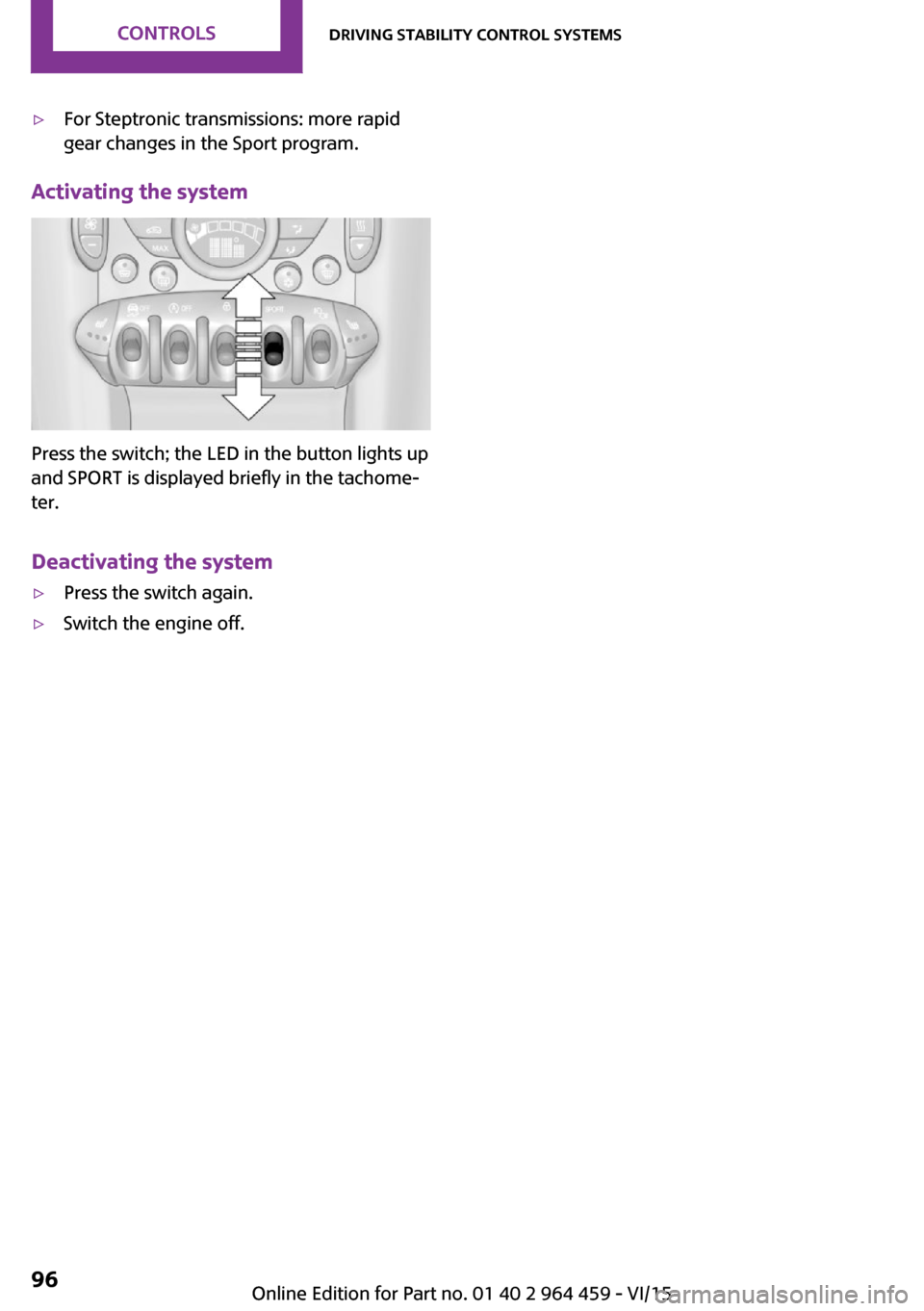
Press the switch; the LED in the button lights up
and SPORT is displayed briefly in the tachome‐
ter.
Deactivating the system
▷Press the switch again.▷Switch the engine off.Seite 96CONTROLSDriving stability control systems96
Online Edition for Part no. 01 40 2 964 459 - VI/15
Page 98 of 282
The displays go out. The stored target speed is
cleared.
Interrupting Press button 2.
The system is interrupted automatically if▷The brakes are applied.▷The clutch pedal is depressed.▷The transmission position D is disengaged.▷DSC intervenes.
Maintaining, storing the current speed
WARNING
The desired speed can be incorrectly ad‐
justed or called up by mistake. There is risk of
an accident. Adjust the desired speed to the
traffic conditions. Watch traffic closely and ac‐
tively interfere in the respective situations. ◀
Press button 1 or button 3.
The current speed is maintained and stored. It
is displayed briefly in the tachometer.
On downhill gradients, it may prove impossible
to maintain the set speed if the engine braking
power is insufficient. On uphill gradients, it may
prove impossible to maintain the set speed if
the engine power output is insufficient.
Increasing speed
▷Press button 1 repeatedly until the desired
speed is reached.
Each time the button is pressed, the speed
increases by approx. 1 mph/1 km/h.▷Press and hold button 1 until the desired
speed is reached.
The vehicle accelerates without pressure on
the accelerator pedal. After the button is
released, the achieved speed is maintained
and stored.Decreasing speed
Press button 3 repeatedly or hold it until the
desired speed is reached.
The functions are the same those when the
speed is increased, only that the speed is re‐
duced.
Resuming a speed stored beforehand Press button 4.
The last stored speed is resumed and main‐
tained.
The stored speed is cleared when the ignition is
switched off.
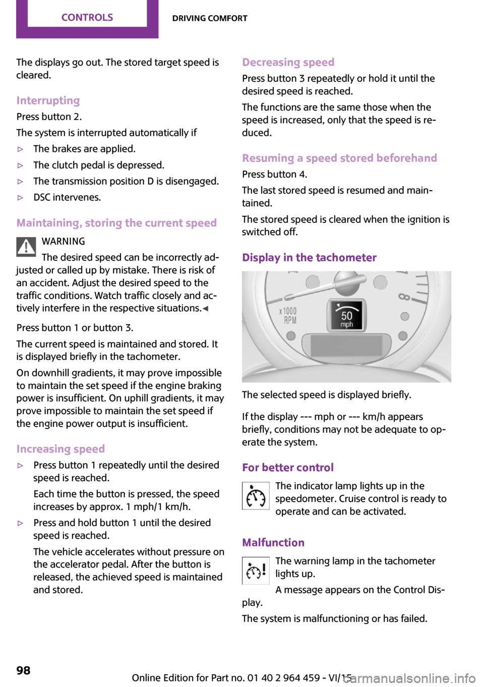
Display in the tachometer
The selected speed is displayed briefly.
If the display --- mph or --- km/h appears
briefly, conditions may not be adequate to op‐
erate the system.
For better control The indicator lamp lights up in the
speedometer. Cruise control is ready to
operate and can be activated.
Malfunction The warning lamp in the tachometer
lights up.
A message appears on the Control Dis‐
play.
The system is malfunctioning or has failed.
Seite 98CONTROLSDriving comfort98
Online Edition for Part no. 01 40 2 964 459 - VI/15
Page 99 of 282

Park Distance Control
PDC
The concept
PDC provides support when parking in reverse.
Signal tones and a visual display indicate that
the vehicle is approaching an object behind it.
Measurements are made by four ultrasound
sensors in the bumpers.
The range of these sensors is approx. 6 ft/2 m.
An acoustic warning is first given:▷By the two corner sensors at ap‐
prox. 24 in/60 cm.▷By the rear middle sensors at approx.
5 ft/1.50 m.
WARNING
Due to high speeds when PDC is acti‐
vated, the warning can be delayed due to phys‐
ical circumstances. There is risk of injuries or
risk of property damage. Avoid approaching an
object quickly. Avoid driving away quickly while
PDC is not yet active. ◀
Automatic operation
The system is activated after approx. one sec‐
ond when reverse gear or selector lever posi‐
tion R is engaged while the engine is running or
the ignition is switched on. Await this short pe‐
riod before setting the vehicle into motion.
Signal tones
The closer the vehicle is to the object, the
shorter the intervals become. If the distance to
a detected object is less than approx.
12 in/30 cm, a continuous tone is sounded.
If the distance remains constant, for example
when driving parallel to a wall, the signal tone
is stopped after approx. 3 seconds.
PDC with visual warning
Displaying the approach to an object on the
Control Display. The contours of distant objects
are displayed on the Control Display before a
signal tone is output. The display is shown on
the Control Display as soon as reverse gear or
selector lever position R is engaged.
System limits WARNING
The system does not relieve from the per‐
sonal responsibility to correctly assess the traf‐
fic situation. There is risk of an accident. Adjust
the driving style to the traffic conditions. Watch
traffic and vehicle surroundings closely and ac‐
tively interfere in the respective situations. ◀
Malfunction The warning light lights up. A message
appears on the Control Display. PDC is
malfunctioning or has failed. Have the
system checked.
To ensure full functionality of the sensors, keep
the sensors clean and free of ice. When using
high-pressure washers, do not spray the sen‐
sors for long periods and maintain a distance of
at least 12 in/30 cm.Seite 99Driving comfortCONTROLS99
Online Edition for Part no. 01 40 2 964 459 - VI/15
Page 103 of 282
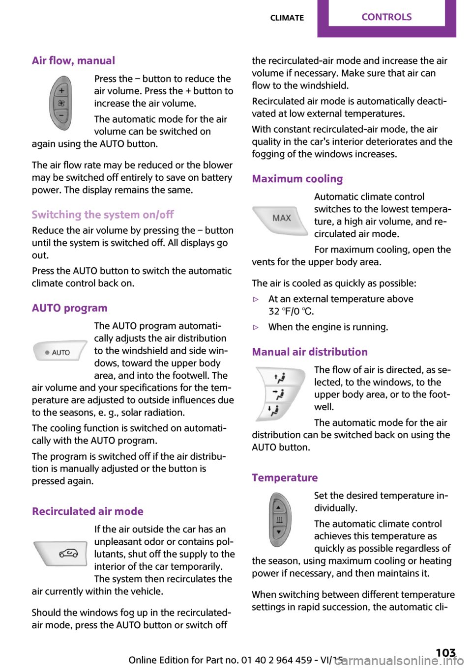
Air flow, manualPress the – button to reduce the
air volume. Press the + button to
increase the air volume.
The automatic mode for the air
volume can be switched on
again using the AUTO button.
The air flow rate may be reduced or the blower
may be switched off entirely to save on battery
power. The display remains the same.
Switching the system on/off Reduce the air volume by pressing the – button
until the system is switched off. All displays go
out.
Press the AUTO button to switch the automatic
climate control back on.
AUTO program The AUTO program automati‐
cally adjusts the air distribution
to the windshield and side win‐
dows, toward the upper body
area, and into the footwell. The
air volume and your specifications for the tem‐
perature are adjusted to outside influences due
to the seasons, e. g., solar radiation.
The cooling function is switched on automati‐
cally with the AUTO program.
The program is switched off if the air distribu‐
tion is manually adjusted or the button is
pressed again.
Recirculated air mode If the air outside the car has an
unpleasant odor or contains pol‐
lutants, shut off the supply to the
interior of the car temporarily.
The system then recirculates the
air currently within the vehicle.
Should the windows fog up in the recirculated-
air mode, press the AUTO button or switch offthe recirculated-air mode and increase the air
volume if necessary. Make sure that air can
flow to the windshield.
Recirculated air mode is automatically deacti‐
vated at low external temperatures.
With constant recirculated-air mode, the air
quality in the car's interior deteriorates and the
fogging of the windows increases.
Maximum cooling Automatic climate control
switches to the lowest tempera‐
ture, a high air volume, and re‐
circulated air mode.
For maximum cooling, open the
vents for the upper body area.
The air is cooled as quickly as possible:▷At an external temperature above
32 ℉/0 ℃.▷When the engine is running.
Manual air distribution
The flow of air is directed, as se‐
lected, to the windows, to the
upper body area, or to the foot‐
well.
The automatic mode for the air
distribution can be switched back on using the
AUTO button.
Temperature Set the desired temperature in‐
dividually.
The automatic climate control
achieves this temperature as
quickly as possible regardless of
the season, using maximum cooling or heating power if necessary, and then maintains it.
When switching between different temperature
settings in rapid succession, the automatic cli‐
Seite 103ClimateCONTROLS103
Online Edition for Part no. 01 40 2 964 459 - VI/15
Page 107 of 282

Canada: if the LED does not flash rapidly af‐
ter approx. 60 seconds, change the dis‐
tance and repeat the step. If programming
was aborted by the hand-held transmitter,
hold down the memory button and press
and release the button on the hand-held
transmitter several times for 2 seconds.
Controls
WARNING
Body parts can be jammed when operat‐
ing remote-controlled systems, e.g. the garage
door, using the universal garage door opener.
There is risk of injuries or risk of property dam‐
age. Make sure that the area of movement of
the respective system is clear during program‐
ming and operation. Also follow the safety in‐
structions of the hand-held transmitter. ◀
The system, such as the garage door, can be
operated using the button on the interior rear‐
view mirror with the engine running or the igni‐
tion switched on. When you are within the re‐
ception range of the system, press and hold the
button until the function is initiated. The LED on
the interior rearview mirror lights up continu‐
ously while the radio signal is being transmit‐
ted.
Deleting stored functions
Press the right and left buttons on the interior
rearview mirror simultaneously for approx.
20 seconds until the LED flashes rapidly. All
stored functions are deleted. The functions can‐
not be deleted individually.
Sun visor Glare protection
Folding down
Fold the sun visor down.
Folding up
Fold the sun visor up.
Glare protection from the side
Folding down1.Fold the sun visor down.2.Detach from the holder and pivot sideways
to the side window.
Folding up
To close the sun visor, proceed in reverse order.
Vanity mirror A vanity mirror is located behind a cover on
each sun visor.
To open, fold the cover up.
Depending on the vehicle equipment, mirror
lighting comes on when the cover is opened.
Digital compass
1Adjustment button on the back of the mir‐
ror2Display
The display shows the main or secondary com‐
pass direction in which the vehicle is traveling.
Operating concept
Various functions can be called up by pressing
the adjustment button with a pointed object
such as a pen. The following adjustment op‐
tions are displayed one after the other, de‐
Seite 107Interior equipmentCONTROLS107
Online Edition for Part no. 01 40 2 964 459 - VI/15
Page 108 of 282
pending on how long the adjustment button is
pressed:▷Press briefly: switch the display on/off.▷3 to 6 seconds: set the compass zone.▷6 to 9 seconds: calibrate the compass.▷9 to 12 seconds: set left-hand/right hand
steering.▷12 to 15 seconds: set the language.
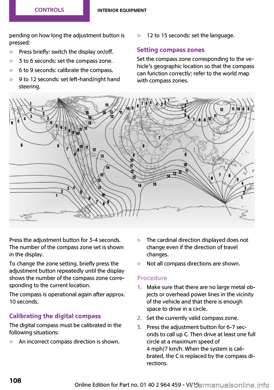
Setting compass zones
Set the compass zone corresponding to the ve‐
hicle's geographic location so that the compass
can function correctly; refer to the world map
with compass zones.
Press the adjustment button for 3‑4 seconds.
The number of the compass zone set is shown
in the display.
To change the zone setting, briefly press the
adjustment button repeatedly until the display
shows the number of the compass zone corre‐
sponding to the current location.
The compass is operational again after approx.
10 seconds.
Calibrating the digital compass The digital compass must be calibrated in the
following situations:▷An incorrect compass direction is shown.▷The cardinal direction displayed does not
change even if the direction of travel
changes.▷Not all compass directions are shown.
Procedure
1.Make sure that there are no large metal ob‐
jects or overhead power lines in the vicinity
of the vehicle and that there is enough
space to drive in a circle.2.Set the currently valid compass zone.3.Press the adjustment button for 6‑7 sec‐
onds to call up C. Then drive at least one full
circle at a maximum speed of
4 mph/7 km/h. When the system is cali‐
brated, the C is replaced by the compass di‐
rections.Seite 108CONTROLSInterior equipment108
Online Edition for Part no. 01 40 2 964 459 - VI/15
Page 132 of 282
Navigation systemVehicle features and op‐
tions
This chapter describes all standard, country-
specific and optional features offered with the
series. It also describes features that are not
necessarily available in your car, e. g., due to
the selected options or country versions. This
also applies to safety-related functions and sys‐
tems.
When using the features and systems described
here, adhere to local regulations.
General information
The navigation system can determine the pre‐
cise position of the vehicle, with the aid of sat‐
ellites and vehicle sensors, and can reliably
guide you to every entered destination.
WARNING
Operating the integrated information sys‐
tem and communication devices while driving
can distract from traffic. It is possible to lose
control of the vehicle. There is risk of an acci‐
dent. Only use the systems or devices when the
traffic situation allows. If necessary stop and
use the systems and devices while the vehicle is
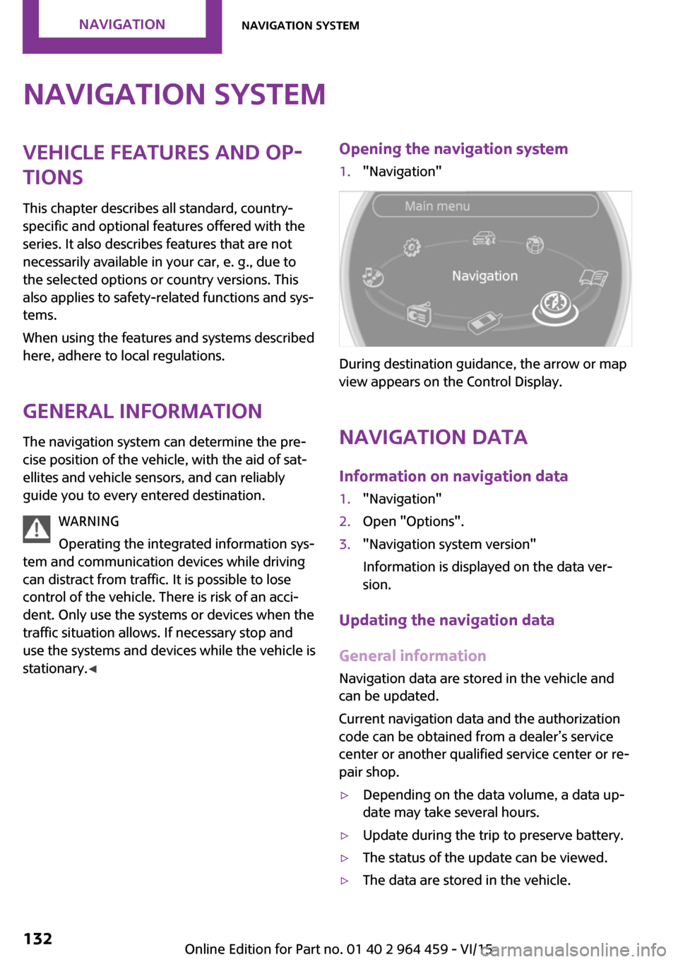
stationary. ◀Opening the navigation system1."Navigation"
During destination guidance, the arrow or map
view appears on the Control Display.
Navigation data
Information on navigation data
1."Navigation"2.Open "Options".3."Navigation system version"
Information is displayed on the data ver‐
sion.
Updating the navigation data
General information
Navigation data are stored in the vehicle and
can be updated.
Current navigation data and the authorization
code can be obtained from a dealer’s service
center or another qualified service center or re‐
pair shop.
▷Depending on the data volume, a data up‐
date may take several hours.▷Update during the trip to preserve battery.▷The status of the update can be viewed.▷The data are stored in the vehicle.Seite 132NAVIGATIONNavigation system132
Online Edition for Part no. 01 40 2 964 459 - VI/15
Page 134 of 282
Destination entryVehicle features and op‐tions
This chapter describes all standard, country-
specific and optional features offered with the
series. It also describes features that are not
necessarily available in your car, e. g., due to
the selected options or country versions. This
also applies to safety-related functions and sys‐
tems.
When using the features and systems described
here, adhere to local regulations.
Overview
In entering your destination, it is possible to se‐
lect from the following options:▷Enter the destination manually, see below.▷Select the destination from the address
book, refer to page 136.▷Last destinations, refer to page 137.▷Special destinations, refer to page 138.▷Destination entry via map, refer to
page 139.▷Using the home address as the destination,
refer to page 137.▷Destination entry by voice, refer to
page 140.
Manual destination en‐
try
General information
The system supports you in entering street
names and house numbers by automatically
completing the entry and providing entry com‐
parisons, refer to page 23.
Stored town/city and street names can be
called up quickly.▷If the existing entries should not be
changed, the entries for the state/province
and town/city can be skipped.▷Destination guidance is started to the town/
city center if no street is entered.
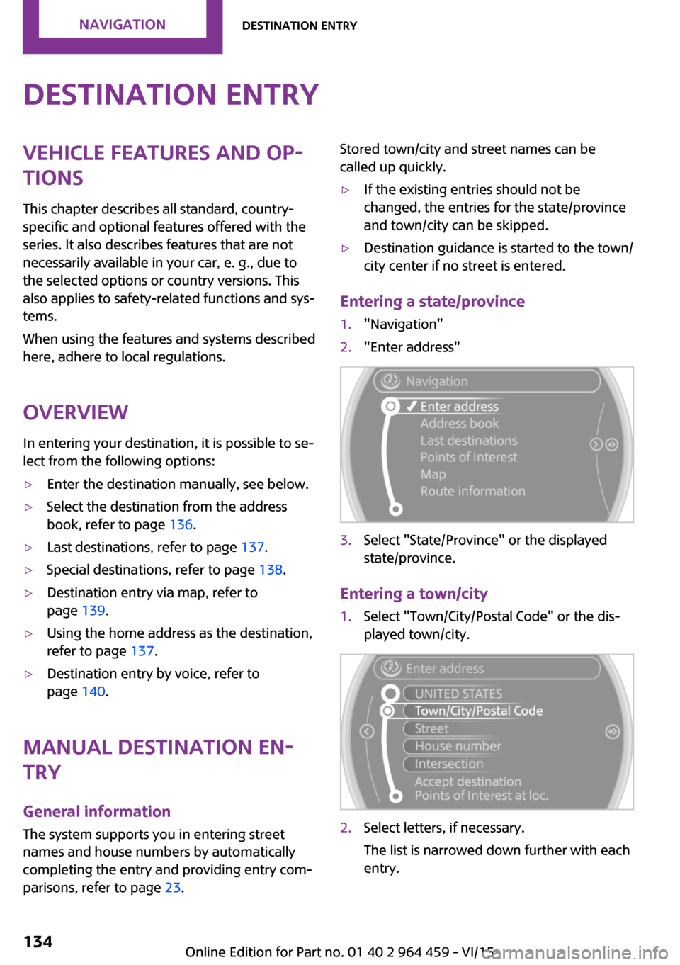
Entering a state/province
1."Navigation"2."Enter address"3.Select "State/Province" or the displayed
state/province.
Entering a town/city
1.Select "Town/City/Postal Code" or the dis‐
played town/city.2.Select letters, if necessary.
The list is narrowed down further with each
entry.Seite 134NAVIGATIONDestination entry134
Online Edition for Part no. 01 40 2 964 459 - VI/15
Page 135 of 282

3.Move the MINI joystick to the right.4.Select the name of the town/city from the
list.
If there are several towns/cities with the same
name:
1.Change to the list of town/city names.2.Highlight the town/city.3.Select the town/city.
Entering the postal code
1.Select "Town/City/Postal Code" or the dis‐
played town/city.2. Select the symbol.3.Select the digits individually.4.Change to the list of postal codes and
towns/cities.5.Highlight the entry.6.Selecting an entry.
The associated destination town/city is dis‐
played.
Entering a street and intersection
1.Select "Street" or the displayed street.2.Enter a street and intersection in the same
way as you would enter a town/city.
If there are several streets with the same name:
1.Change to the list of street names.2.Highlight the street.3.Select the street.
Alternative: enter the street address
and house number
1.Select "Street" or the displayed street.2.Enter the street as you would the town/city.3."House number"4.Select the numbers.5.Change to the list of house numbers.6.Select a house number or range of house
numbers.Street does not exist in the destination
city/town
The desired street does not exist in the speci‐
fied city/town because it belongs to another
part of the city/town.1."Navigation"2."Enter address"3.Select "Street" or the displayed street.4.Change to the list of street names.5.Select "In" with the state/province currently
displayed.
All streets of the selected state/province are
offered. The associated town/city is dis‐
played after the street name.6.Select the letters.7.Change to the list of street names.8.Highlight the street.9.Select the street.
Starting destination guidance after
entering the destination
1."Accept destination"2."Start guidance" or "Add as another
destination"Seite 135Destination entryNAVIGATION135
Online Edition for Part no. 01 40 2 964 459 - VI/15