ignition MINI Hardtop 2 Door 2002 Owner's Guide
[x] Cancel search | Manufacturer: MINI, Model Year: 2002, Model line: Hardtop 2 Door, Model: MINI Hardtop 2 Door 2002Pages: 140, PDF Size: 1.63 MB
Page 60 of 140

58
CLOCK COMPUTER
*
Settings
From ignition key position 1:
Left button: hours
Right button: minutes
Move forward in increments:
Press the button
or
Fast forward:
Press and hold the button
Changeover from 24-hour to 12-hour
mode:
Press both buttons at the same time for
approx. 5 seconds.
Mode selectionWith the ignition key in position 1 and
higher, you can use the button in the turn
signal indicator lever to retrieve informa-
tion from the computer for display in the
tachometer. By pressing the button briefly,
you can call up a new function for display.
The displays appear in the following order:
Outside temperature, cruising range,
average fuel consumption, average vehicle
speed.
Starting with ignition key position 1, the
last active setting is displayed.
If the vehicle is equipped with a navi-
gation system, see chapter covering
the computer in the navigation system
Owner's Manual.<
Page 62 of 140

60
AUTOMATIC STABILITY CONTROL PLUS TRACTION (ASC+T)
*
The concept
This system optimizes vehicle stability and
traction, especially when just starting off,
when accelerating or when cornering.
ASC+T recognizes the danger present in
traction loss and will increase driving
stability and traction by reducing the
engine's output, and if necessary, by
applying the brakes to the front wheels.
ASC+T is operational each time you start
the engine.
The laws of physics cannot be
repealed, even with ASC+T. An appro-
priate driving style always remains the
responsibility of the driver. Avoid using the
additional safety margin provided by the
system as an excuse for taking unnecessary
risks.
Do not make any modifications to the
ASC+T system. Allow only authorized tech-
nicians to perform service procedures on
the ASC+T.<
Switch off the ASC+TBriefly press the switch.
The indicator lamp stays lit.
When driving with snow chains or to "rock
free" in snow, it can be helpful to switch off
the ASC+T for a brief period.
To maintain vehicle stability, always
drive with the ASC+T switched on
whenever possible.
Indicator lamp
The indicator lamp on the instru-
ment cluster will go out shortly
after the ignition has been
switched on, see pages 16, 17.
If the indicator lamp flashes:
ASC+T controls the drive and braking
forces.
If the indicator lamp fails to go out
after the engine is started, or if it
comes on during normal driving and stays
on:
If the system is either defective or was
switched off with the button, then the
stabilizing applications described are no
longer available. You can, however, drive
the vehicle normally without ASC+T.
In the event of a malfunction, please see
your MINI center, see pages 16, 17.<
Page 63 of 140

61
OVERVIEW REPAIRS OPERATIONCONTROLS DATA INDEX
DYNAMIC STABILITY CONTROL (DSC)
*
The concept
This system maintains driving stability
even in critical driving situations.
The system optimizes vehicle stability
during acceleration and when starting
from a full stop, as well as optimizing trac-
tion. In addition, it recognizes unstable
vehicle conditions, such as under- or over-
steering, and, as far as is possible within
the laws of physics, helps keeping the
vehicle on a steady course by reducing the
rpms and brake applications to the indi-
vidual wheels.
The DSC is operational every time you start
the engine. DSC contains the functions
Antilock Brake System ABS/Electronic Brake
Force Distribution EBV/ASC+T.
The laws of physics cannot be
repealed, even with DSC. An appro-
priate driving style always remains the
responsibility of the driver. We therefore
urge you to avoid using the additional
safety margin of the system as an excuse
for taking risks.
Do not make any modifications to the DSC
system. Allow only authorized technicians
to perform service procedures on the
DSC.<
To switch off the DSCBriefly press the switch.
The indicator lamp stays lit.
When driving with snow chains, it may be
effective to switch off the DSC for a brief
period.
To maintain stability, always drive
with the DSC switched on whenever
possible.
Indicator lamp
The indicator lamp on the instru-
ment cluster will go out shortly
after the ignition has been
switched on, see pages 16, 17.
If the indicator lamp flashes:
DSC controls the drive and braking forces.
If the indicator lamp fails to go out
after the engine is started, or if it
comes on during normal driving and stays
on:
If the system is either defective or was
switched off with the button, then the
stabilizing applications described are no
longer available. The vehicle will remain
completely operational, however, without
DSC.
In the event of a malfunction, please see
your MINI center, see pages 16, 17.<
Page 64 of 140

62
FLAT TIRE MONITORThe conceptThe tire inflation pressure is determined
from the signals of the ABS sensors.
The system provides an alert whenever the
tire inflation pressure drops below the
pressure in any other tire. RequirementSo that the system can "familiarize" itself
with the correct inflation pressure, please
do the following:
1. Check the tire inflation pressure in all
tires
2. Compare them with the inflation pres-
sure table, see page 81, and adjust the
pressures if necessary
3. Initialize the system.
Check the tire inflation pressure
regularly and correct it if necessary,
see page 80.<
Flat tire
The indicator lamp in the instru-
ment cluster informs you by
flashing when the tire inflation
pressure of a tire drops in relation to any
other tire. In addition, an acoustic signal is
sounded.
>Vehicles with safety (run-flat) tires, see
notes on pages 110, 80, 84
>Vehicles with normal tires, see notes on
pages 106, 80.
The Flat Tire Monitor cannot alert you
to severe and sudden tire damage
caused by external factors. Another factor
which the Flat Tire Monitor does not recog-
nize is the balanced and very gradual pres-
sure loss that takes place in all tires over an
extended period of time.<
MalfunctionsAs long as there is still a malfunction, the
yellow indicator lamp on the instrument
cluster will stay lit up.
The indicator lamp also lights up in the
event of a system malfunction.
Please contact your MINI center in these
cases.
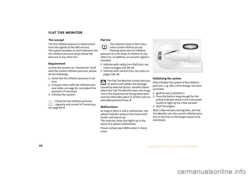
Initializing the systemOnly initialize the system if the inflation
pressure, e. g. after a tire change, has been
corrected.
1. Ignition key in position 2
2. Press the button long enough for the
yellow indicator lamp in the instrument
cluster to light up for a few seconds
3. Start the engine.
After a few minutes driving time, the Flat
Tire Monitor sets the current inflation pres-
sure in the tires as the target values to be
monitored.
Page 65 of 140

63
OVERVIEW REPAIRS OPERATIONCONTROLS DATA INDEX
FLAT TIRE MONITOR PARK DISTANCE CONTROL (PDC)*
Do not initialize the system when
snow chains are fitted. When driving
with snow chains, false alarms can occur or
pressure losses might not be detected.<
In the following situations false
alarms can also occur under certain
circumstances or the detection of inflation
pressure loss can be delayed:
>When driving on roads covered with
snow or on other slippery road surfaces
>A sporty driving style (slip at the driven
wheels, high lateral accelerations).<
The conceptThe PDC assists you when you back into a
parking space. A signal warns you of the
distance to an obstacle. To do this, four
ultrasonic sensors in the rear bumper
measure the distance to the nearest object.
The range for the sensors located at both
rear corners ends approx. 2 ft (60 cm)
behind the bumpers. The range for the two
middle sensors is slightly less than 5 ft
(1.5 meters).
The system starts to operate automatically
about one second after you select reverse
with the ignition key in position 2. PDC is
deactivated when you shift back out of
reverse. Acoustical signalsThe distance to the nearest object is indi-
cated by a tone sounding at various inter-
vals. As the distance between vehicle and
object decreases, the intervals between the
tones become shorter. A continuous tone
indicates the presence of an object less
than 9 in (20 cm) away.
The warning signal is canceled after
approx. three seconds if the distance to the
obstacle remains constant during this time
(if you are moving parallel to a wall, for
instance).System malfunctions will be indicated by
a continuous high-pitched tone when the
system is activated the first time. Please
have your MINI center resolve the problem.
Even with PDC, final responsibility for
estimating the distance between the
vehicle and any obstructions always
remains with the driver. Even when sensors
are involved, there is a blind spot in which
objects cannot be detected. Moreover, the
detection of obstructions can approach the
physical limits of ultrasonic measurement,
as occurs e. g. in the case of thin and
wedge-shaped objects.
Certain sources of sound, such as a loud
radio, could drown out the PDC signal
tone.<
Keep the sensors clean and free of ice
or snow in order to ensure that they
will continue to operate effectively.
Do not apply high pressure spray to the
sensors for a prolonged period of time.
Always maintain a distance of more than
4 in (10 cm).<
Page 72 of 140

70
GLOVE COMPARTMENT ASHTRAY/BEVERAGE HOLDER CIGARETTE LIGHTERTo open:
Pull the handle.
The light goes on.
To close:
Fold the door up.
To prevent injury in the event of an
accident, close the glove compart-
ment immediately after use.<
AshtrayThe ashtray is located in one of the
beverage holders in the center console.
In the rear, an ashtray can also be fitted in
the beverage holder at the end of the
center console. Beverage holdersThere are two beverage holders at the front
of the center console. Another is located at
the end of the center console.
From ignition key position 1:
Press the cigarette lighter in.
Remove as soon as the lighter jumps back
out.
Hold or touch the hot cigarette
lighter by the knob only. Holding or
touching it in other areas could result in
burns.
a rating of approx. 200 Watts at 12 Volts.
Avoid damaging the socket with plugs of
different shapes or sizes.
Page 118 of 140

116
TOW-STARTING AND TOWINGTow-starting
On vehicles with Continuously Vari-
able automatic Transmission (CVT), it
is not permitted to start the engine by tow-
starting. The transmission could be
damaged.
For jump-starting, see page 113
.<
Only tow-start vehicles with a catalytic
converter when the engine is cold, other-
wise, unburned fuel in the catalytic
converter could catch fire. It is better to use
jumper cables.
1. Switch on the hazard warning flashers
(comply with national regulations)
2. Ignition key in position 2
3. Engage 3rd gear
4. Tow-start with the clutch pedal pressed
5. Slowly release the clutch
6. When the engine starts, press the clutch
pedal again
7. Switch off the hazard warning flashers.
Have the cause of the starting problems
rectified by your MINI center.
Towing
Only tow vehicles with Continuously
Variable automatic Transmission
(CVT) with the front wheels raised or on a
special transport vehicle, otherwise the
transmission can be damaged.<
1 Ignition key in position 1:
The brake lamps, turn signals, horn and
windshield wipers can be operated
2 Switch on the hazard warning flashers
(comply with national regulations).
If the electrical system has failed, place
some kind of warning on the towed vehicle,
e. g. a sign or warning triangle in the rear
window.
Ensure that if the electrical system
has failed the ignition key is in posi-
tion 1, otherwise the steering lock could
engage and make it impossible to steer the
vehicle.
When the engine is not running, there is no
power-assist. This means that greater
effort is required for braking and
steering.<
Towing with a commercial tow truck >Do not tow with sling-type equipment
>Use a wheel-lift or flatbed carrier
>Please comply with applicable towing
laws.
Never allow passengers to ride in a
towed vehicle for any reason.<
Page 131 of 140

EVERYTHING FROM A TO Z
129
OVERVIEW REPAIRS OPERATION CONTROLS DATA INDEX
C
California Proposition 65
Warning 97
Can holder, see Beverage
holder 70
Car wash 94
Car-care products 94
Care
chrome parts 94
floor mats 95
imitation leather 95
leather 95
light-alloy wheels 94
of upholstery 94
plastic parts 95
rubber parts 95
safety belts 95
special parts 94
windshield wipers 95
Cargo 72
securing 72
stowing 72
Caring for your vehicle 94
Cassette player, see separate
Owner's Manual
CD changer, see separate
Owner's Manual CD player, see separate
Owner's Manual
Center (high-mount) brake
lamp
bulb replacement 104
Central locking system 23,
26
Changing tires
space-saver spare tire 106
Child seat 38
Child-restraint systems 38
Chrome parts 94
Cigarette lighter 70
socket 70
Cleaning rear window 52
Cleaning windshield 52
Clock 58
Closing
from inside 26
from outside 23
Clothes hooks 77
Clutch 76
Cockpit 12
Combination of wheels/
tires 84
Compact Disc player, see
separate Owner's Manual
Compression ratio 120 Computer 58
average fuel
consumption 59
average speed 59
cruising range 59
exterior temperature 59
Condensation 65,
68
Consumption 59
Consumption display 55
Contents 2
Continuously Variable
automatic Transmission
(CVT)
electronic transmission
control module (EP) 48
gear display 48
ignition 42
interlock 42
manual mode 47
parking 47
reverse gear 47
selector lever
shiftlock 42,
46
shiftlock 46
Sport program 47
Steptronic 46
towing 116
tow-starting 116
transmission fault 48 Control elements 12
Convenience feature
sliding/tilt sunroof 25
windows 25
Convenience operation
via central locking
system 26
Coolant 91
Coolant level 91
Coolant temperature
gauge 56
Cooling 65,
68
Copyright notice 6
Correct sitting posture with
airbags 31
safety belt 31
Cruise control 17,
18,
53
Cruising range 59
Cup holder, see Beverage
holder 70
Curb weight 122
Currency of the Owner's
Manual 7
Cylinders 120
Page 133 of 140

EVERYTHING FROM A TO Z
131
OVERVIEW REPAIRS OPERATION CONTROLS DATA INDEX
G
Gasoline 78
Gasoline gauge 55
Gear display 48
Continuously Variable
automatic Transmission
(CVT) 48
General driving notes 76
Glove compartment 70
Glove compartment lamps
bulb replacement 105
Grilles 66,
69
Gross weight 122
H
Handbrake 44
Hazard warning flashers 12
Head airbags 37
Head restraints 34
Headlamp cleaning
system 52,
89
filling 89
Headlamp flasher 49
Headlamps
care 94,
101
cleaning 52 Heated
outside mirrors 36
rear window 65,
68
seats 34
windshield 65, 68
windshield washer jets 52
Heavy cargo 72
Height 121
High beams 17, 49
bulb replacement 101
Hood 16,
86
Horn 12
Hubcap remover 100,
106
I
Ignition lock 42
Illuminated vanity mirror 36
Imitation leather 95
Imprint 6
Indicator lamps 15
Individual air distribution 69
INSPECTION 57
Instrument cluster, see Display
elements 13
Instrument lighting 50
Instrument panel 12
Interface socket
for Onboard Diagnostics 96 Interior lamps 50
bulb replacement 104
Interior rearview mirror 36
automatic dimming 37
Interlock 42
Interval display 93
J
Jack 100,
106
Jump-starting 113,
114
K
Keys 22
multifunction steering
wheel 18
Kickdown 47 L
Lamps 49,
101
backup lamps 103
brake lamp 103,
104
daytime driving lamps 49
fog lamps 50
footwell lamps 105
front fog lamps 102
glove compartment 105
high beams 101
instrument lighting 50 interior lamps 50,
104
license plate lamp 104
low beams 49,
101
luggage compartment
lamps 105
parking lamps 49,
102
reading lamps 50
rear fog lamp 103
standing lamps 49, 102
tail lamp 103
turn signal indicators 102
xenon lamps 101
Lashing eyes 72
LATCH child-restraint
system 41
Leather care 95
LED light-emitting diodes 51
Length 121
License plate lamp
bulb replacement 104
Light-alloy wheels 94
"Lights on" warning 49
Loading 72
Load-securing devices 72
Low beams 49
bulb replacement 101
Luggage compartment 72
content 122