engine MINI Hardtop 2 Door 2004 Owner's Manual
[x] Cancel search | Manufacturer: MINI, Model Year: 2004, Model line: Hardtop 2 Door, Model: MINI Hardtop 2 Door 2004Pages: 152, PDF Size: 1.41 MB
Page 5 of 152
3
OVERVIEW REPAIRS OPERATION CONTROLS DATA INDEX
Driving:
Ignition lock41
Starting the engine41
Switching off the engine43
Parking brake43
Manual transmission44
Continuously Variable automatic
Transmission (CVT)45
Parking lamps/Low beams48
Turn signal indicator/Headlamp
flasher49
Instrument lighting49
Fog lamps49
Interior lamps50
Washer/wiper system50
Cruise control52
Everything under control:
Odometer54
Tachometer54
Fuel gauge54
Coolant temperature gauge55
Service interval display56
Clock56
Onboard computer57
Technology for safety and driving
convenience:
All Season traction Control (ASC)59
Dynamic Stability Control (DSC)60
Antilock Brake System (ABS)61
Flat Tire Monitor62
Park Distance Control (PDC)64
Airbags65
Controlling the climate for pleasant
driving:
Air conditioning system67
Automatic climate control70
Interior conveniences:
Glove compartment73
Ashtray, beverage holders74
Cigarette lighter, 12 V power supply74
Loading and transporting cargo:
Cargo area75
Loading cargo76
Roof-mounted luggage rack78
OPERATION, CARE, MAINTENANCE
Special operating instructions:
Break-in procedures82
General driving notes83
Refueling84
Fuel specifications85
Brake system86
Wheels and tires:
Tire inflation pressure87
Tire coding89
Tire condition91
Wheel and tire replacement92
Run Flat tires93
Snow chains94
Page 6 of 152
CONTENTS
4
In the engine compartment:
Bonnet95
Engine compartment: MINI COOPER96
Engine compartment: MINI COOPER S97
Washer fluid98
Engine oil98
Coolant100
Brake fluid101
Maintenance and care:
MINI Maintenance System102
Caring for your vehicle103
Vehicle storage105
Laws and regulations:
OBD socket106
California Proposition 65 warning107
OWNER SERVICE PROCEDURES
Replacement procedures:
Onboard tool kit110
Windshield wiper blades110
Lamps and bulbs111
Repairing a flat tire116
Changing tires: MINI with space-saver
spare tire117
MINI Mobility System121
Battery124
Fuses125
Giving and receiving assistance:
Jump-starting126
Towing128
TECHNICAL DATA
Engine data132
Dimensions133
Weights134
Capacities135
Page 15 of 152
13
OVERVIEW REPAIRS OPERATION CONTROLS DATA INDEX
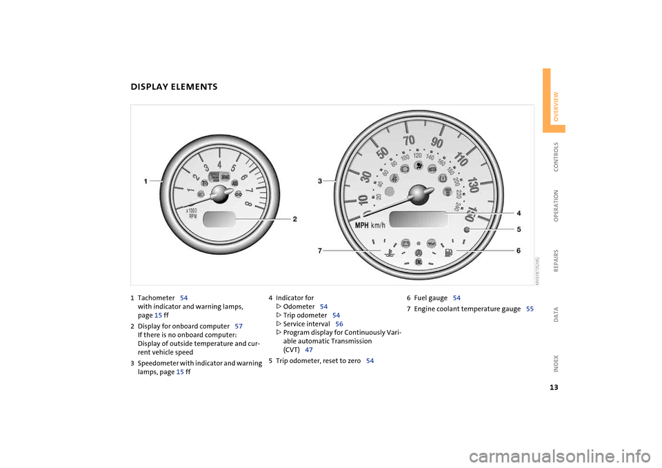
DISPLAY ELEMENTS
1Tachometer54
with indicator and warning lamps,
page 15 ff
2Display for onboard computer57
If there is no onboard computer:
Display of outside temperature and cur-
rent vehicle speed
3Speedometer with indicator and warning
lamps, page 15 ff4Indicator for
>
Odometer54
>
Trip odometer54
>
Service interval56
>
Program display for Continuously Vari-
able automatic Transmission
(CVT)47
5Trip odometer, reset to zero546Fuel gauge54
7Engine coolant temperature gauge55
Page 17 of 152
15
OVERVIEW REPAIRS OPERATION CONTROLS DATA INDEX
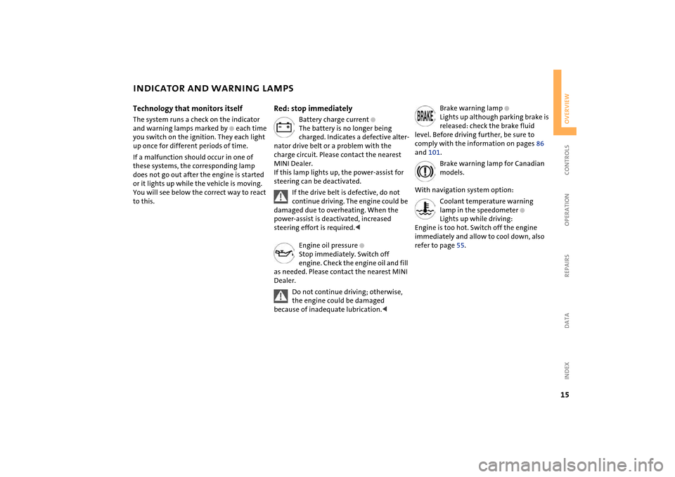
INDICATOR AND WARNING LAMPS
Technology that monitors itself
The system runs a check on the indicator
and warning lamps marked by
+
each time
you switch on the ignition. They each light
up once for different periods of time.
If a malfunction should occur in one of
these systems, the corresponding lamp
does not go out after the engine is started
or it lights up while the vehicle is moving.
You will see below the correct way to react
to this.
Red: stop immediately
Battery charge current
+
The battery is no longer being
charged. Indicates a defective alter-
nator drive belt or a problem with the
charge circuit. Please contact the nearest
MINI Dealer.
If this lamp lights up, the power-assist for
steering can be deactivated.
If the drive belt is defective, do not
continue driving. The engine could be
damaged due to overheating. When the
power-assist is deactivated, increased
steering effort is required.
<
Engine oil pressure
+
Stop immediately. Switch off
engine. Check the engine oil and fill
as needed. Please contact the nearest MINI
Dealer.
Do not continue driving; otherwise,
the engine could be damaged
because of inadequate lubrication.
<
Brake warning lamp
+
Lights up although parking brake is
released: check the brake fluid
level. Before driving further, be sure to
comply with the information on pages 86
and 101.
Brake warning lamp for Canadian
models.
With navigation system option:
Coolant temperature warning
lamp in the speedometer
+
Lights up while driving:
Engine is too hot. Switch off the engine
immediately and allow to cool down, also
refer to page 55.
Page 19 of 152
17
OVERVIEW REPAIRS OPERATION CONTROLS DATA INDEX
INDICATOR AND WARNING LAMPS
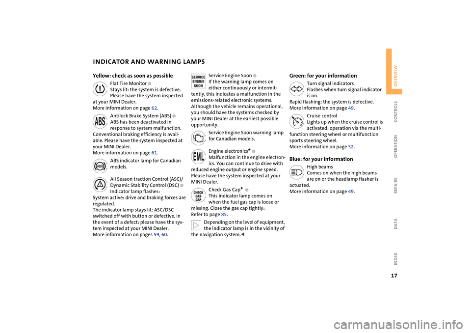
Yellow: check as soon as possible
Flat Tire Monitor
+
Stays lit: the system is defective.
Please have the system inspected
at your MINI Dealer.
More information on page 62.
Antilock Brake System (ABS)
+
ABS has been deactivated in
response to system malfunction.
Conventional braking efficiency is avail-
able. Please have the system inspected at
your MINI Dealer.
More information on page 61.
ABS indicator lamp for Canadian
models.
All Season traction Control (ASC)/
Dynamic Stability Control (DSC)
+
Indicator lamp flashes:
System active: drive and braking forces are
regulated.
The indicator lamp stays lit: ASC/DSC
switched off with button or defective. In
the event of a defect: please have the sys-
tem inspected at your MINI Dealer.
More information on pages 59, 60.
Service Engine Soon
+
If the warning lamp comes on
either continuously or intermit-
tently, this indicates a malfunction in the
emissions-related electronic systems.
Although the vehicle remains operational,
you should have the systems checked by
your MINI Dealer at the earliest possible
opportunity.
Service Engine Soon warning lamp
for Canadian models.
Engine electronics
*
+
Malfunction in the engine electron-
ics. You can continue to drive with
reduced engine output or engine speed.
Please have the system inspected at your
MINI Dealer.
Check Gas Cap
*
+
This indicator lamp comes on
when the fuel gas cap is loose or
missing. Close the gas cap tightly:
Refer to page 85.
Depending on the level of equipment,
the indicator lamp is in the vicinity of
the navigation system.
<
Green: for your information
Turn signal indicators
Flashes when turn signal indicator
is on.
Rapid flashing: the system is defective.
More information on page 49.
Cruise control
Lights up when the cruise control is
activated: operation via the multi-
function steering wheel or multifunction
sports steering wheel.
More information on page 52.
Blue: for your information
High beams
Comes on when the high beams
are on or the headlamp flasher is
actuated.
More information on page 49.
Page 30 of 152
28
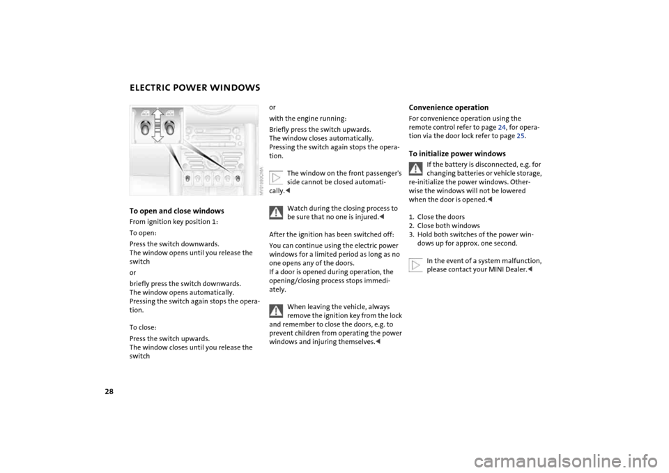
ELECTRIC POWER WINDOWSTo open and close windows From ignition key position 1:
To open:
Press the switch downwards.
The window opens until you release the
switch
or
briefly press the switch downwards.
The window opens automatically.
Pressing the switch again stops the opera-
tion.
To close:
Press the switch upwards.
The window closes until you release the
switch
or
with the engine running:
Briefly press the switch upwards.
The window closes automatically.
Pressing the switch again stops the opera-
tion.
The window on the front passenger's
side cannot be closed automati-
cally.<
Watch during the closing process to
be sure that no one is injured.<
After the ignition has been switched off:
You can continue using the electric power
windows for a limited period as long as no
one opens any of the doors.
If a door is opened during operation, the
opening/closing process stops immedi-
ately.
When leaving the vehicle, always
remove the ignition key from the lock
and remember to close the doors, e.g. to
prevent children from operating the power
windows and injuring themselves.<
Convenience operationFor convenience operation using the
remote control refer to page 24, for opera-
tion via the door lock refer to page 25.To initialize power windows
If the battery is disconnected, e.g. for
changing batteries or vehicle storage,
re-initialize the power windows. Other-
wise the windows will not be lowered
when the door is opened.<
1. Close the doors
2. Close both windows
3. Hold both switches of the power win-
dows up for approx. one second.
In the event of a system malfunction,
please contact your MINI Dealer.<
Page 43 of 152
41
OVERVIEW REPAIRS OPERATIONCONTROLS DATA INDEX
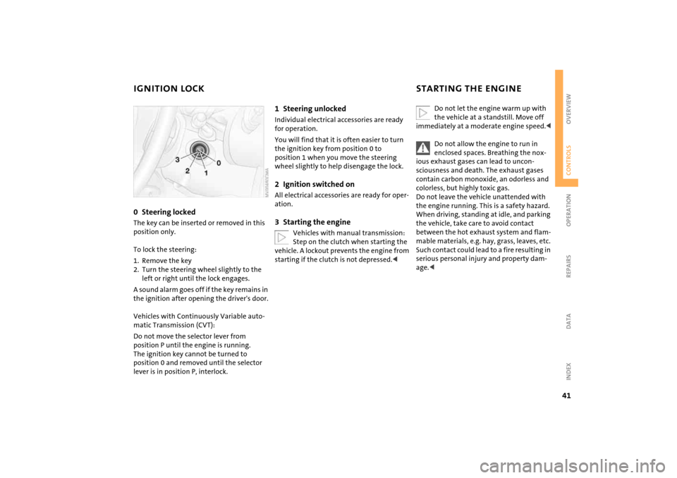
IGNITION LOCK STARTING THE ENGINE0Steering locked The key can be inserted or removed in this
position only.
To lock the steering:
1. Remove the key
2. Turn the steering wheel slightly to the
left or right until the lock engages.
A sound alarm goes off if the key remains in
the ignition after opening the driver's door.
Vehicles with Continuously Variable auto-
matic Transmission (CVT):
Do not move the selector lever from
position P until the engine is running.
The ignition key cannot be turned to
position 0 and removed until the selector
lever is in position P, interlock.
1Steering unlockedIndividual electrical accessories are ready
for operation.
You will find that it is often easier to turn
the ignition key from position 0 to
position 1 when you move the steering
wheel slightly to help disengage the lock.2Ignition switched onAll electrical accessories are ready for oper-
ation.3Starting the engine
Vehicles with manual transmission:
Step on the clutch when starting the
vehicle. A lockout prevents the engine from
starting if the clutch is not depressed.<
Do not let the engine warm up with
the vehicle at a standstill. Move off
immediately at a moderate engine speed.<
Do not allow the engine to run in
enclosed spaces. Breathing the nox-
ious exhaust gases can lead to uncon-
sciousness and death. The exhaust gases
contain carbon monoxide, an odorless and
colorless, but highly toxic gas.
Do not leave the vehicle unattended with
the engine running. This is a safety hazard.
When driving, standing at idle, and parking
the vehicle, take care to avoid contact
between the hot exhaust system and flam-
mable materials, e.g. hay, grass, leaves, etc.
Such contact could lead to a fire resulting in
serious personal injury and property dam-
age.<
Page 44 of 152
42
STARTING THE ENGINEStartingWhen starting the engine, do not press the
accelerator pedal.
Do not actuate the starter for too
short a time. Do not turn it for more
than approx. 20 seconds. Release the igni-
tion key immediately when the engine
starts.
Extended starting attempts, characterized
by excessively frequent or long periods
with the starter engaged, can lead to dam-
age in the catalytic converter.<
If the engine does not start on the first
attempt, for instance if the engine is very
hot or cold:
When starting the engine, press the gas
pedal down halfway.
When first starting the engine at very low
temperatures, from +57 / –156:
When starting the engine, press the gas
pedal down halfway. For the initial start
attempt, allow the starter to remain
engaged somewhat longer, approx.
10 seconds.
Manual transmission1. Engage the parking brake
2. Put the manual gearshift lever in neutral
3. Press the clutch pedal
4. Start the engine.
Move the gearshift lever to neutral
position and engage the parking
brake before leaving your vehicle with the
engine running.
Do not leave the vehicle unattended with
the engine running. This is a safety haz-
ard.<
Continuously Variable automatic
Transmission (CVT)1. Press the footbrake
2. Put the selector lever in position P or N
3. Start the engine.
Move the selector lever to position P
and engage the parking brake before
leaving your vehicle with the engine run-
ning.
Do not leave the vehicle unattended with
the engine running. This is a safety haz-
ard.<
Page 45 of 152
43
OVERVIEW REPAIRS OPERATIONCONTROLS DATA INDEX
SWITCHING OFF THE ENGINE PARKING BRAKE
You should never remove the ignition
key when the vehicle is in motion, as
the steering lock could engage.
When you leave the vehicle, always remove
the ignition key and engage the steering
lock.
When you park on downward slopes,
engage the parking brake.<
Manual transmissionTurn the ignition key to position 1 or 0.Continuously Variable automatic
Transmission (CVT)Engage selector lever position P, turn the
ignition key to position 1 or 0.
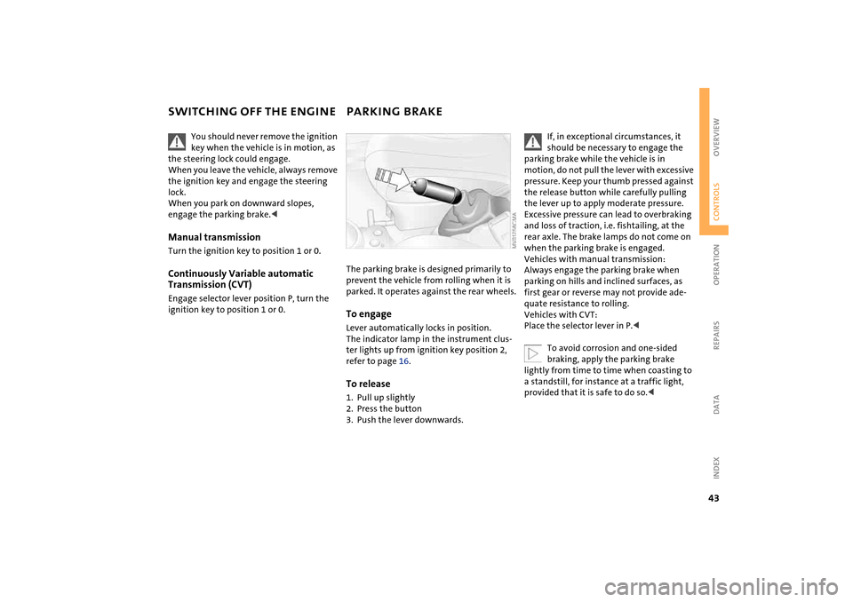
The parking brake is designed primarily to
prevent the vehicle from rolling when it is
parked. It operates against the rear wheels.To engageLever automatically locks in position.
The indicator lamp in the instrument clus-
ter lights up from ignition key position 2,
refer to page 16.To release1. Pull up slightly
2. Press the button
3. Push the lever downwards.
If, in exceptional circumstances, it
should be necessary to engage the
parking brake while the vehicle is in
motion, do not pull the lever with excessive
pressure. Keep your thumb pressed against
the release button while carefully pulling
the lever up to apply moderate pressure.
Excessive pressure can lead to overbraking
and loss of traction, i.e. fishtailing, at the
rear axle. The brake lamps do not come on
when the parking brake is engaged.
Vehicles with manual transmission:
Always engage the parking brake when
parking on hills and inclined surfaces, as
first gear or reverse may not provide ade-
quate resistance to rolling.
Vehicles with CVT:
Place the selector lever in P.<
To avoid corrosion and one-sided
braking, apply the parking brake
lightly from time to time when coasting to
a standstill, for instance at a traffic light,
provided that it is safe to do so.<
Page 47 of 152
45
OVERVIEW REPAIRS OPERATIONCONTROLS DATA INDEX
CONTINUOUSLY VARIABLE AUTOMATIC TRANSMISSION (CVT)
*
You can drive with a continuously variable
shifting CVT. In addition, you can also shift
manually.
When in manual selection mode, you have
the option of changing gears by using
either the selector lever or the shift paddles
on the steering wheel.
Under normal operating conditions, fuel
consumption is lowest when driving in
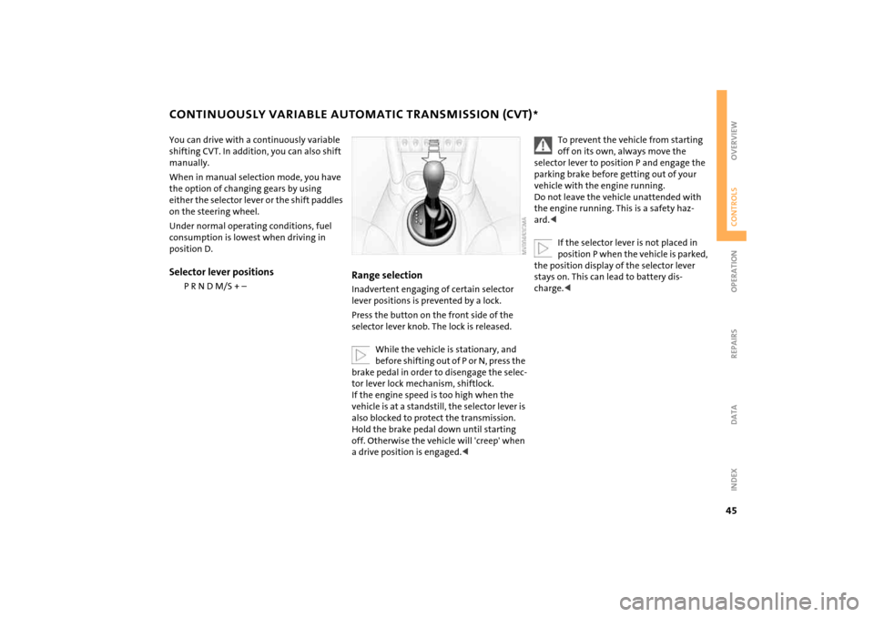
position D.Selector lever positions
P R N D M/S + –
Range selection Inadvertent engaging of certain selector
lever positions is prevented by a lock.
Press the button on the front side of the
selector lever knob. The lock is released.
While the vehicle is stationary, and
before shifting out of P or N, press the
brake pedal in order to disengage the selec-
tor lever lock mechanism, shiftlock.
If the engine speed is too high when the
vehicle is at a standstill, the selector lever is
also blocked to protect the transmission.
Hold the brake pedal down until starting
off. Otherwise the vehicle will 'creep' when
a drive position is engaged.<
To prevent the vehicle from starting
off on its own, always move the
selector lever to position P and engage the
parking brake before getting out of your
vehicle with the engine running.
Do not leave the vehicle unattended with
the engine running. This is a safety haz-
ard.<
If the selector lever is not placed in
position P when the vehicle is parked,
the position display of the selector lever
stays on. This can lead to battery dis-
charge.<