ECU MINI Hardtop 2 Door 2005 User Guide
[x] Cancel search | Manufacturer: MINI, Model Year: 2005, Model line: Hardtop 2 Door, Model: MINI Hardtop 2 Door 2005Pages: 165, PDF Size: 2.32 MB
Page 87 of 165
85
OVERVIEW REPAIRS OPERATIONCONTROLS DATA INDEX
LUGGAGE COMPARTMENT IN THE MINILuggage compartment cover When the tailgate is opened, the luggage
compartment cover is also raised.
Never place any heavy or hard objects on the luggage compartment cover;
otherwise occupants could be injured dur
-
ing braking maneuvers.<
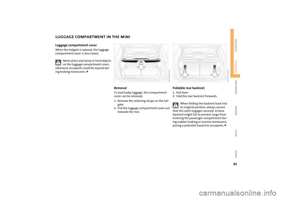
RemovalTo load bulky luggage, the compartment
cover can be removed. 1. Remove the retaining straps on the tail
-
gate
2. Pull the luggage compartment cover out
towards the rear.
Foldable rear backrest 1. Pull lever2. Fold the rear backrest forwards.
When folding the backrest back into its original position, always ensure
that the catch engages securely. A loose
backrest might fail to prevent cargo from
entering the passenger compartment dur
-
ing sudden braking or evasive maneuvers,
posing a potential hazard to occupants.<
Page 88 of 165

86
LUGGAGE COMPARTMENT IN THE MINI CONVERTIBLE
LOADING CARGO
Loading aidWhen the convertible top is closed, you can
load the vehicle more easily by releasing
the convertible top and folding it up.1. Release the convertible top using the
handles, arrows 12. Lift the convertible top, arrow 23. Fold back the handles and place them on
brackets
3.
Lock the handles in place again com
-
pletely so that the convertible top
can be operated.<
Expanding the luggage compartment volumeYou can enlarge the luggage compartment
volume when the convertible top is closed. 1. Fold the convertible top upwards, refer
to Loading aid2. Remove the luggage compartment cover
from the brackets, arrow 1, and engage
it on the upper support pins, arrow 2.
Move the luggage compartment cover to its lower position again so
that the convertible top can be operated.<
Through-loading system To be able to transport larger objects, the
rear backrest can be folded.1. Unlock the catch for the rear backrest
with an ignition key or master key, refer
to Manual release in the MINI Convert
-
ible on page
30
2. Pull the lever to release the catch3. Fold the backrest forward.
When folding the backrest back into its original position, always ensure
that the catch engages securely. A loose
backrest might fail to prevent cargo from
entering the passenger compartment dur
-
ing sudden braking or evasive maneuvers,
posing a potential hazard to occupants.<
Page 90 of 165
88
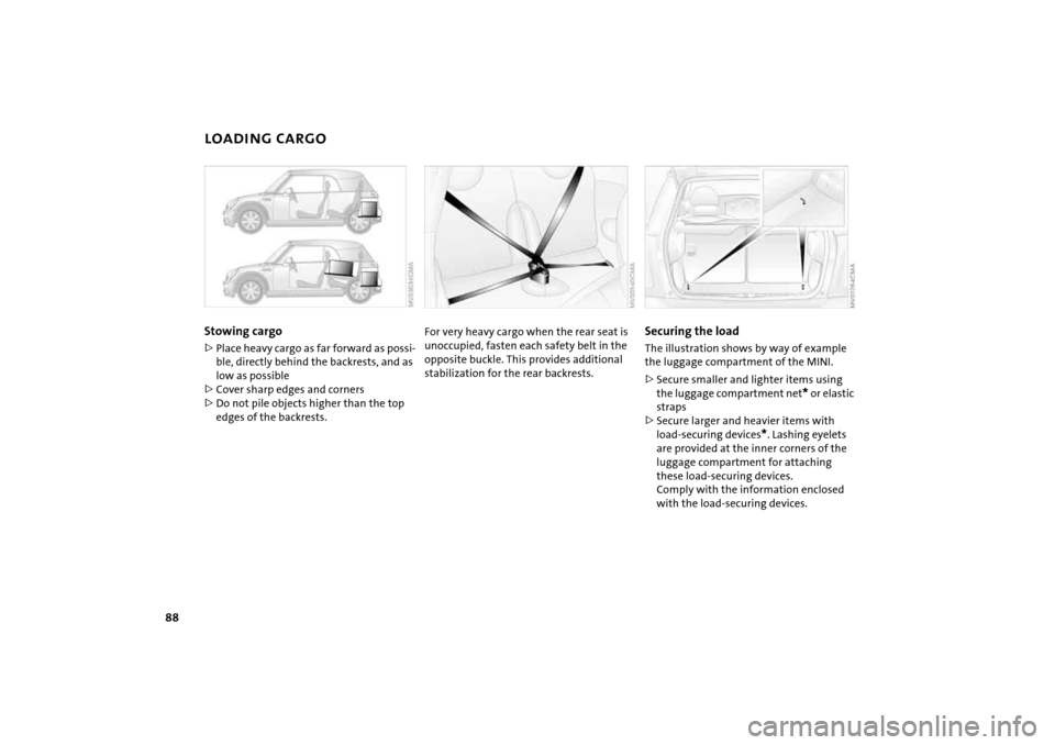
LOADING CARGOStowing cargo >Place heavy cargo as far forward as possi
-
ble, directly behind the backrests, and as
low as possible>Cover sharp edges and corners>Do not pile objects higher than the top
edges of the backrests.
For very heavy cargo when the rear seat is unoccupied, fasten each safety belt in the
opposite buckle. This provides additional
stabilization for the rear backrests.
Securing the load The illustration shows by way of example
the luggage compartment of the MINI.>Secure smaller and lighter items using
the luggage compartment net
* or elastic
straps
>Secure larger and heavier items with
load-securing devices
*. Lashing eyelets
are provided at the inner corners of the
luggage compartment for attaching
these load-securing devices.
Comply with the information enclosed
with the load-securing devices.
Page 91 of 165
89
OVERVIEW REPAIRS OPERATIONCONTROLS DATA INDEX
ROOF-MOUNTED LUGGAGE RACK
*
Always position and secure the load as described above. If you do not, it
can pose a danger to the passengers during
braking and evasive maneuvers, for exam
-
ple.
Do not exceed the permissible gross weight
and axle load, refer to page
143
ff; other
-
wise the vehicle's operating safety is no
longer assured and it will not be in compli
-
ance with the certification regulations.
Do not stow heavy or hard objects in the
passenger compartment without first
securing them. Otherwise they would be
thrown around during braking and evasive
maneuvers and endanger the occupants.<
When loading a roof-mounted lug
-
gage rack on the MINI, make sure
that there is sufficient space for the move
-
ment of the glass sunroof and that no
objects protrude into the swiveling area of
the tailgate, as otherwise damage can
occur. Do not secure the roof-mounted lug
-
gage rack to the MINI's trim strips or to the
MINI Convertible top. Otherwise, the lack
of a secure hold could lead to damage or
accidents.<
Special roof-mounted luggage racks for your MINI are available as acces
-
sories from your MINI Dealer.<
Page 107 of 165
105
OVERVIEW REPAIRSOPERATIONCONTROLS DATA INDEX
BONNET
Do not attempt to service your vehi
-
cle if you do not have the required
technical background. If you are not famil
-
iar with the regulations to be observed,
have the necessary work on your vehicle
carried out only by a MINI Dealer or a work
-
shop that has specially trained personnel
working in accordance with the specifica
-
tions of the MINI manufacturer.
Work that is improperly carried out could
result in consequential damage and pose
safety hazards.<
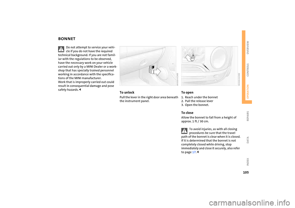
To unlockPull the lever in the right door area beneath
the instrument panel.
To open1. Reach under the bonnet2. Pull the release lever3. Open the bonnet.To closeAllow the bonnet to fall from a height of
approx.
1 ft / 30
cm.
To avoid injuries, as with all closing procedures be sure that the travel
path of the bonnet is clear when it is closed.
If it is determined that the bonnet is not
completely closed while driving, stop
immediately and close it securely, also refer
to page
17.<
Page 122 of 165
120
ONBOARD TOOL KIT
WIPER BLADES
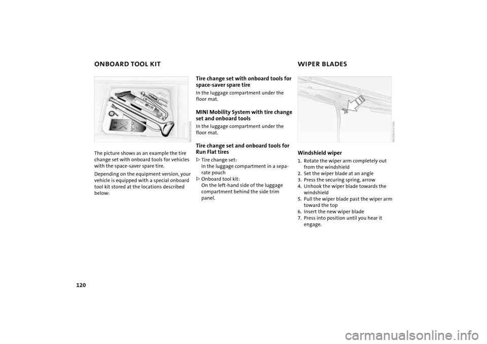
The picture shows as an example the tire change set with onboard tools for vehicles
with the space-saver spare tire.Depending on the equipment version, your
vehicle is equipped with a special onboard
tool kit stored at the locations described
below:
Tire change set with onboard tools for
space-saver spare tireIn the luggage compartment under the
floor mat.MINI Mobility System with tire change
set and onboard tools In the luggage compartment under the
floor mat.Tire change set and onboard tools for
Run Flat tires >Tire change set:
In the luggage compartment in a sepa
-
rate pouch>Onboard tool kit:
On the left-hand side of the luggage
compartment behind the side trim
panel.
Windshield wiper1. Rotate the wiper arm completely out
from the windshield 2. Set the wiper blade at an angle3. Press the securing spring, arrow4. Unhook the wiper blade towards the
windshield5. Pull the wiper blade past the wiper arm
toward the top6. Insert the new wiper blade7. Press into position until you hear it
engage.
Page 128 of 165
126
SPACE-SAVER SPARE TIRE
*
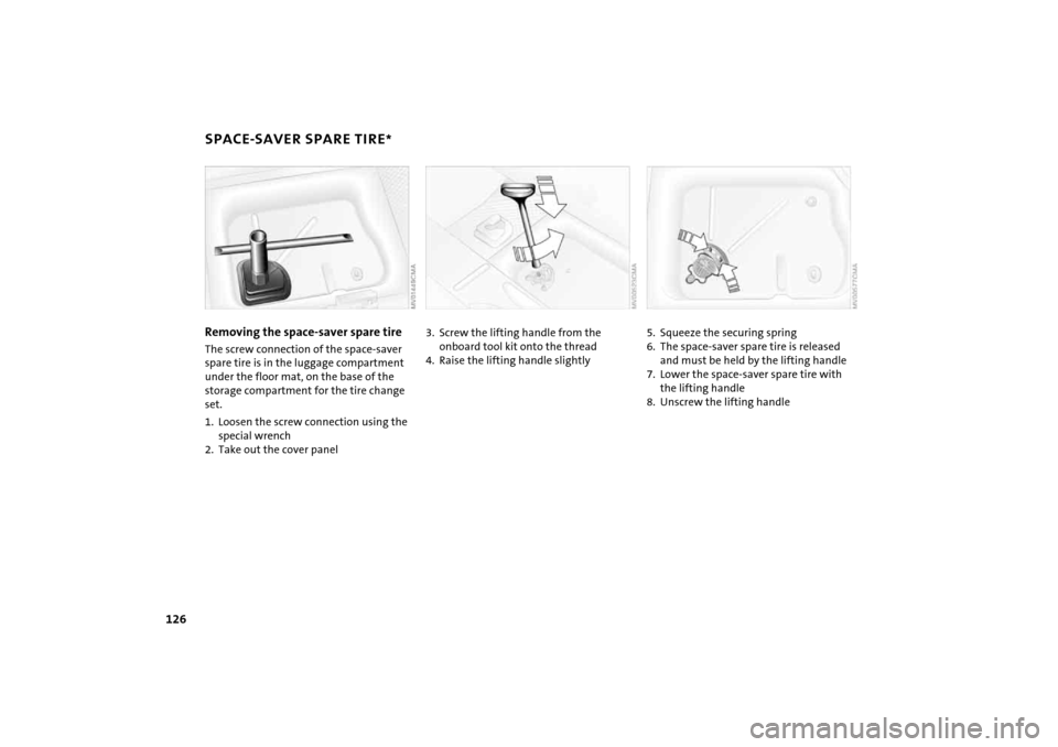
Removing the space-saver spare tireThe screw connection of the space-saver
spare tire is in the luggage compartment
under the floor mat, on the base of the
storage compartment for the tire change
set.1. Loosen the screw connection using the
special wrench2. Take out the cover panel
3.
Screw the lifting handle from the onboard tool kit onto the thread
4. Raise the lifting handle slightly
5.
Squeeze the securing spring
6. The space-saver spare tire is released
and must be held by the lifting handle7. Lower the space-saver spare tire with
the lifting handle8. Unscrew the lifting handle
Page 129 of 165

127
OVERVIEW REPAIRSOPERATION CONTROLS DATA INDEX
SPACE-SAVER SPARE TIRE
*
CHANGING TIRES
9.
Pull out the space-saver spare tire towards the rear underneath the vehi
-
cle
10. Position the space-saver spare tire with
the valve facing upwards11. Unscrew the valve extension from the
valve of the space-saver spare tire12. Unscrew the dust cap from the exten
-
sion and place it on the valve of the
space-saver spare tire.Due to its different dimensions, the damaged wheel cannot be placed in
the recess for the space-saver spare tire.<
Driving with the space-saver spare tireDrive cautiously. Do not exceed a speed of
50 mph
/ 80
km/h.
You must expect changes in vehicle han
-
dling such as lower track stability during
braking, longer braking distances and
changes in self-steering properties when
close to the handling limit. These effects
are more pronounced when driving with
winter tires.
Only one space-saver spare tire may be mounted at one time. Reinstall a
wheel and tire of the original size as soon
as possible.
soon as possible and have the new wheel/
tire assembly balanced.<
Additional safety measures in the event of a tire change:
Change the tire only on a level, firm surface
which is not slippery.
The vehicle or the jack could slip sideways
on soft or slippery support surfaces, such as
snow, ice, flagstones, etc..
Do not use a wooden block or similar object
as a support base for the jack, as this would
prevent it from extending to its full support
height and reduce its load-carrying capac
-
ity.
Do not lie under the vehicle or start the
engine when the vehicle is supported by
the jack – risk of fatal injury.
125
.<
1. For vehicles with a space-saver spare
tire:
Place the folding chock behind the front
wheel on the other side of the vehicle;
on downward inclines, place it in front of
this wheel. If the wheel is changed on a
surface with a more severe slope, take
additional precautions to secure the
vehicle from rolling
2. Loosen the lug bolts by a half turn.
Page 130 of 165

128
CHANGING TIRES Jacking up the vehicle 1. Place the jack at the jacking point closest
to the wheel.
The jack base must be perpendicular to
the surface beneath the jacking point
The vehicle jack is designed for changing wheels only. Do not
attempt to raise another vehicle model
with it or to raise any load of any kind. To
do so could cause accidents and personal
injury.<
2.
During jacking up, insert the jack head in the square recess of the jacking point
3. Jack the vehicle up until the wheel you
are changing is raised from the ground.Mounting a wheel1. Unscrew the lug bolts and remove the
wheel2. Remove accumulations of mud or dirt
from the mounting surfaces of the
wheel and hub. Clean the lug bolts3. Mount the new wheel4. Screw at least two lug bolts finger-tight
into opposite bolt holes 5. Screw in the remaining bolts
6. Tighten all the lug bolts firmly in a diag
-
onal pattern
7. Lower the vehicle8. Remove the jack.Tightening the lug bolts Tighten the lug bolts in a diagonal pattern.
As soon as possible, have the secure seating of the lug bolts, tightening
torque 88.5
lb ft / 120
Nm, checked using a
calibrated torque wrench. Otherwise, a
wheel coming loose can lead to a severe
accident.<
Replace the defective tire as soon as possi
-
ble and have the new wheel/tire assembly
balanced.
Page 134 of 165

132
BATTERYStorage location MINI COOPER and MINI COOPER Convert
-
ible:The battery is located in the engine com
-
partment. Exact location, refer to page
106
.
MINI COOPER
S and MINI COOPER
S Con
-
vertible:The battery is located in the luggage com
-
partment under the floor mat.Battery careThe battery is absolutely maintenance-free,
that is, the original electrolyte will normally
last for the service life of the battery under
moderate climatic conditions. Your MINI
Dealer will be glad to advise you if you have
any questions regarding the battery. Charging the batteryOnly charge the battery in the vehicle via
the terminals in the engine compartment
with the engine switched off, refer to
'Jump-starting', page
134
ff.
Disposal
After replacing old batteries, return the used batteries to your MINI
Dealer or to a recycling point. Maintain the
battery in an upright position for transport
and storage. Secure the battery to prevent
it from tilting during transport.<
Power failure After a temporary power failure, e.g. due to
a discharged battery, some of your vehicle's
equipment will function only to a limited
extent and must be reinitialized or read
-
justed. Individual settings are also lost and
must be reprogrammed:>Time:
Must be reset, refer to page
63
>Electric power windows:
Must be reinitialized, refer to page
32
>Radio
*:
The stations must be reset, refer to the
Owner's Manual for Radio>Navigation system
*:
It may take some time for its operability
to be restored, refer to the Owner's Man
-
ual for Navigation System.