check engine MINI Hardtop 2 Door 2005 User Guide
[x] Cancel search | Manufacturer: MINI, Model Year: 2005, Model line: Hardtop 2 Door, Model: MINI Hardtop 2 Door 2005Pages: 165, PDF Size: 2.32 MB
Page 113 of 165
111
OVERVIEW REPAIRSOPERATIONCONTROLS DATA INDEX
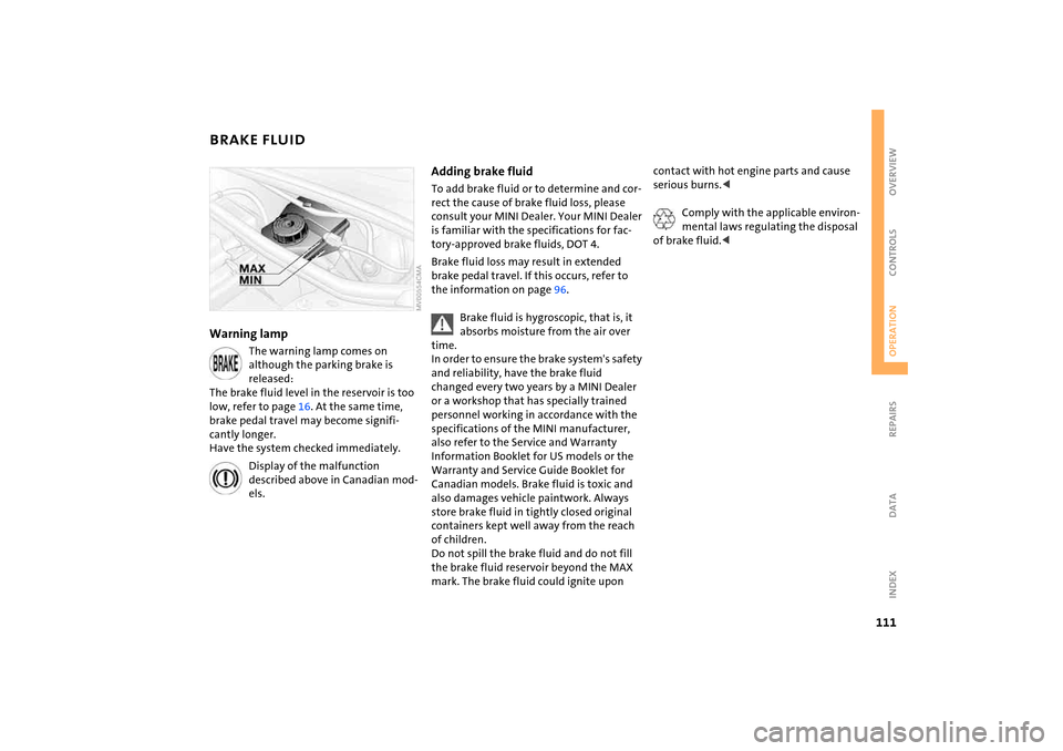
BRAKE FLUIDWarning lamp
The warning lamp comes on although the parking brake is
released:
The brake fluid level in the reservoir is too
low, refer to page
16. At the same time,
brake pedal travel may become signifi
-
cantly longer.
Have the system checked immediately.
Display of the malfunction described above in Canadian mod
-
els.
Adding brake fluid To add brake fluid or to determine and cor
-
rect the cause of brake fluid loss, please
consult your MINI Dealer. Your MINI Dealer
is familiar with the specifications for fac
-
tory-approved brake fluids,
DOT
4.
Brake fluid loss may result in extended
brake pedal travel. If this occurs, refer to
the information on page
96.
Brake fluid is hygroscopic, that is, it absorbs moisture from the air over
time.
In order to ensure the brake system's safety
and reliability, have the brake fluid
changed every two years by a MINI Dealer
or a workshop that has specially trained
personnel working in accordance with the
specifications of the MINI manufacturer,
also refer to the Service and Warranty
Information Booklet for US
models or the
Warranty and Service Guide Booklet for
Canadian models. Brake fluid is toxic and
also damages vehicle paintwork. Always
store brake fluid in tightly closed original
containers kept well away from the reach
of children.
Do not spill the brake fluid and do not fill
the brake fluid reservoir beyond the MAX
mark. The brake fluid could ignite upon
contact with hot engine parts and cause
serious burns.<
Comply with the applicable environ
-
mental laws regulating the disposal
of brake fluid.<
Page 114 of 165

112
MINI MAINTENANCE SYSTEMThe MINI maintenance system helps main
-
tain your vehicle's road safety and opera
-
tional safety. Please bear in mind that regular mainte
-
nance is not only necessary for the safety of
your vehicle, but also plays a significant
role in maintaining the resale value of the
vehicle.
Service interval displayWhile conventional systems specify main
-
tenance according to fixed distances
driven, the MINI Maintenance System takes
account of the operating conditions of the
vehicle, for distances can be driven in many
different ways:
60,000
miles
/ 100,000
km short distance
operation can not be equated with
60,000
miles
/ 100,000
km long distance
operation from a maintenance standpoint.
The condition-based MINI Maintenance
System includes the Engine Oil Service and
Inspections I and II.Determining the maintenance intervals
according to the actual use of the vehicle
covers every kind of operating situation.
People who drive very little, i.e. much less
than 6,000
miles
/ 10,000
km per year,
should have the engine oil changed at least
every 2 years since oil deteriorates over
time, regardless of use.
For more information on the service inter
-
val display, refer to page
65.
Service and Warranty Information
Booklet for US models, Warranty and
Service Guide Booklet for Canadian
models For additional information on maintenance
intervals and procedures, please refer to
the Service and Warranty Information
Booklet for US
models or the Warranty and
Service Guide Booklet for Canadian models.
As a precaution against rust, it is advisable
to have the body checked for damage from
rocks or gravel at the same time, depending
upon operating conditions.
The manufacturer of your MINI rec
-
ommends having maintenance and
repair work carried out only by a MINI
Dealer or a workshop that has specially
trained personnel working in accordance
with the specifications of the MINI manu
-
facturer.
Make sure that maintenance work is con
-
firmed with an entry in the Service and
Warranty Information Booklet for
US
models or the Warranty and Service
Guide Booklet for Canadian models. These
entries are your proof that the vehicle has
received regular maintenance.<
Page 115 of 165
113
OVERVIEW REPAIRSOPERATIONCONTROLS DATA INDEX
OBD SOCKET
CARING FOR YOUR VEHICLE
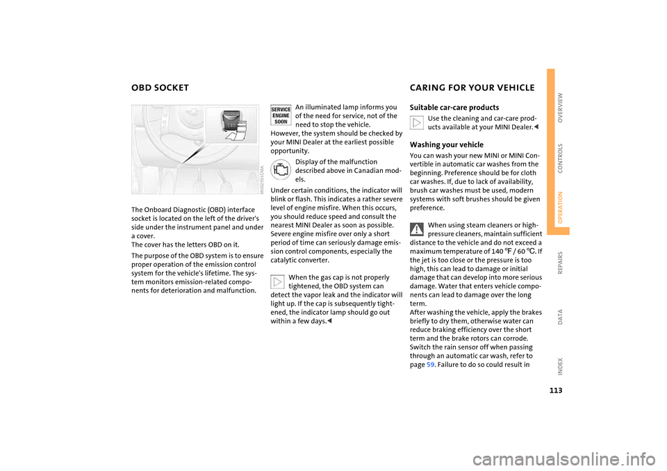
The Onboard Diagnostic (OBD) interface socket is located on the left of the driver's
side under the instrument panel and under
a cover.
The cover has the letters OBD on it.The purpose of the OBD system is to ensure
proper operation of the emission control
system for the vehicle's lifetime. The sys
-
tem monitors emission-related compo
-
nents for deterioration and malfunction.
An illuminated lamp informs you of the need for service, not of the
need to stop the vehicle.
However, the system should be checked by
your MINI Dealer at the earliest possible
opportunity.
Display of the malfunction described above in Canadian mod
-
els.
Under certain conditions, the indicator will
blink or flash. This indicates a rather severe
level of engine misfire. When this occurs,
you should reduce speed and consult the
nearest MINI Dealer as soon as possible.
Severe engine misfire over only a short
period of time can seriously damage emis
-
sion control components, especially the
catalytic converter.
When the gas cap is not properly tightened, the OBD system can
detect the vapor leak and the indicator will
light up. If the cap is subsequently tight
-
ened, the indicator lamp should go out
within a few days.<
Suitable car-care products
Use the cleaning and car-care prod
-
ucts available at your MINI Dealer.<
Washing your vehicleYou can wash your new MINI or MINI Con
-
vertible in automatic car washes from the
beginning. Preference should be for cloth
car washes. If, due to lack of availability,
brush car washes must be used, modern
systems with soft brushes should be given
preference.
When using steam cleaners or high-pressure cleaners, maintain sufficient
distance to the vehicle and do not exceed a
maximum temperature of 140
7/ 60
6. If
the jet is too close or the pressure is too
high, this can lead to damage or initial
damage that can develop into more serious
damage. Water that enters vehicle compo
-
nents can lead to damage over the long
term.
After washing the vehicle, apply the brakes
briefly to dry them, otherwise water can
reduce braking efficiency over the short
term and the brake rotors can corrode.
Switch the rain sensor off when passing
through an automatic car wash, refer to
page
59. Failure to do so could result in
Page 129 of 165

127
OVERVIEW REPAIRSOPERATION CONTROLS DATA INDEX
SPACE-SAVER SPARE TIRE
*
CHANGING TIRES
9.
Pull out the space-saver spare tire towards the rear underneath the vehi
-
cle
10. Position the space-saver spare tire with
the valve facing upwards11. Unscrew the valve extension from the
valve of the space-saver spare tire12. Unscrew the dust cap from the exten
-
sion and place it on the valve of the
space-saver spare tire.Due to its different dimensions, the damaged wheel cannot be placed in
the recess for the space-saver spare tire.<
Driving with the space-saver spare tireDrive cautiously. Do not exceed a speed of
50 mph
/ 80
km/h.
You must expect changes in vehicle han
-
dling such as lower track stability during
braking, longer braking distances and
changes in self-steering properties when
close to the handling limit. These effects
are more pronounced when driving with
winter tires.
Only one space-saver spare tire may be mounted at one time. Reinstall a
wheel and tire of the original size as soon
as possible.
soon as possible and have the new wheel/
tire assembly balanced.<
Additional safety measures in the event of a tire change:
Change the tire only on a level, firm surface
which is not slippery.
The vehicle or the jack could slip sideways
on soft or slippery support surfaces, such as
snow, ice, flagstones, etc..
Do not use a wooden block or similar object
as a support base for the jack, as this would
prevent it from extending to its full support
height and reduce its load-carrying capac
-
ity.
Do not lie under the vehicle or start the
engine when the vehicle is supported by
the jack – risk of fatal injury.
125
.<
1. For vehicles with a space-saver spare
tire:
Place the folding chock behind the front
wheel on the other side of the vehicle;
on downward inclines, place it in front of
this wheel. If the wheel is changed on a
surface with a more severe slope, take
additional precautions to secure the
vehicle from rolling
2. Loosen the lug bolts by a half turn.
Page 136 of 165
134
JUMP-STARTINGWhen your battery is discharged, you can
use two jumper cables to start your vehicle
with power from the battery in a second
vehicle. Correspondingly you can help start
another vehicle. Only use jumper cables
with fully insulated handles on the termi
-
nal clamps.Preparing for jump-starting
Do not touch live wiring and cables on a running engine. There is a risk of
fatal injury if you do this. Carefully observe
the following instructions to avoid per
-
sonal injury and/or damage to either vehi
-
cle or both vehicles. Make sure that there is
no contact between the bodywork of the
two vehicles to avoid a short circuit haz
-
ard.<
1. Check whether the battery of the sup
-
port vehicle has 12
Volts and approxi
-
mately the same capacity measured in
Ah. These data are printed on the bat
-
tery
2. Switch off the engine of the support
vehicle3. Switch off any electrical systems and
components in both vehicles.Connect the jumper cables
Always adhere to this sequence when connecting the jumper cables; failure
to observe this procedure can lead to spark
-
ing and pose an injury hazard.<
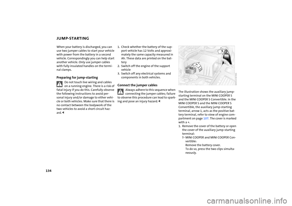
The illustration shows the auxiliary jump-starting terminal on the MINI
COOPER S
and the MINI COOPER
S Convertible. In the
MINI COOPER
S and the MINI COOPER
S
Convertible, the auxiliary jump-starting
terminal, arrow
1, acts as the positive bat
-
tery terminal, refer to view of engine com
-
partment on page
107
. The cover is marked
with a
+.
1. Remove the cover of the battery or open
the cover of the auxiliary jump-starting
terminal:
>MINI COOPER and MINI COOPER Con
-
vertible:
Remove the battery cover.
To do so, press the two clips simulta
-
neously.
Page 137 of 165
135
OVERVIEW REPAIRSOPERATION CONTROLS DATA INDEX
JUMP-STARTING
>MINI COOPER
S and MINI COOPER
S
Convertible:
Open the cover of the auxiliary jump-
starting terminal, arrow
1
2. Connect one terminal clamp of the
plus/+
jumper cable to the positive bat
-
tery terminal or to an auxiliary jump-
starting terminal of the support vehicle
3. Connect the other terminal clamp of the
plus/+ jumper cable to the positive bat
-
tery terminal or to an auxiliary jump-
starting terminal of the vehicle to be
started
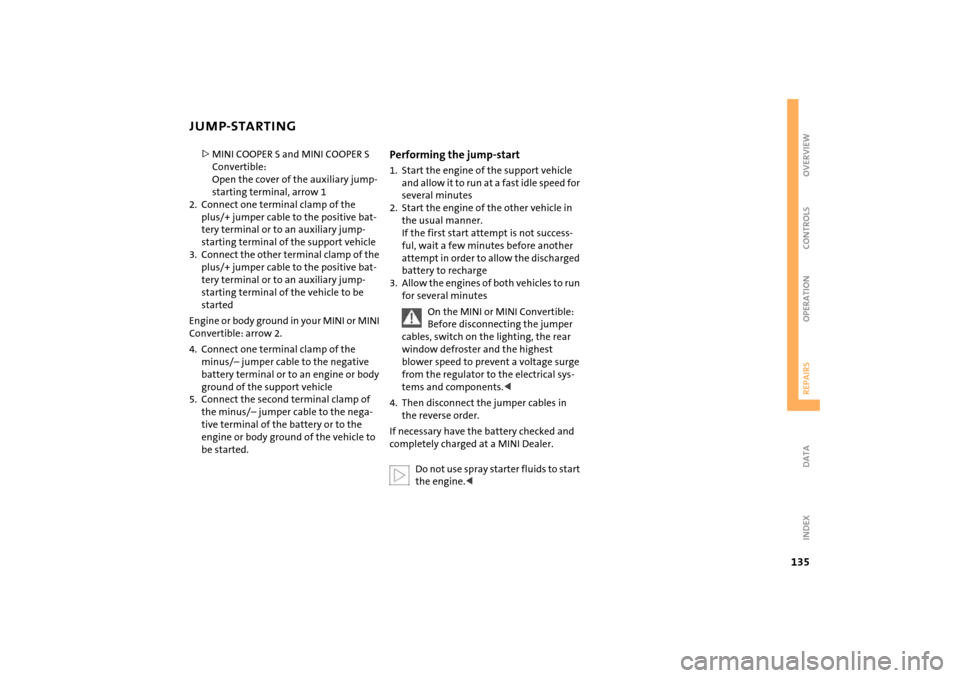
Engine or body ground in your MINI or MINI
Convertible: arrow
2.
4. Connect one terminal clamp of the
minus/– jumper cable to the negative
battery terminal or to an engine or body
ground of the support vehicle5. Connect the second terminal clamp of
the minus/– jumper cable to the nega
-
tive terminal of the battery or to the
engine or body ground of the vehicle to
be started.
Performing the jump-start1. Start the engine of the support vehicle
and allow it to run at a fast idle speed for
several minutes2. Start the engine of the other vehicle in
the usual manner.
If the first start attempt is not success
-
ful, wait a few minutes before another
attempt in order to allow the discharged
battery to recharge
3. Allow the engines of both vehicles to run
for several minutes
On the MINI or MINI Convertible:
Before disconnecting the jumper
cables, switch on the lighting, the rear
window defroster and the highest
blower speed to prevent a voltage surge
from the regulator to the electrical sys
-
tems and components.<
4. Then disconnect the jumper cables in
the reverse order.If necessary have the battery checked and
completely charged at a MINI Dealer.
Do not use spray starter fluids to start the engine.<
Page 139 of 165

137
OVERVIEW REPAIRSOPERATION CONTROLS DATA INDEX
TOWING AND TOW-STARTINGWith a tow bar:
The towing vehicle must not be lighter than the vehicle being towed;
otherwise, vehicle handling can no longer
be controlled.<
The towing eyelets of both vehicles should
be on the same side. If the tow bar can only
be used in a diagonal position, please note
the following:>Clearance and maneuverability will be
strictly limited in corners>The inclination of the tow bar produces
lateral force.
Only attach the tow bar to the towing eyelets. Other parts of the vehicles
could otherwise be damaged.<
With a tow rope: When the towing vehicle is driving off,
make sure that the tow rope is taut.
Use nylon ropes or straps for towing because they prevent sudden jerking
movements. Attach the tow rope only to
the towing eyelets. Other parts of the vehi
-
cles could otherwise be damaged.<
With a tow truck:Have the MINI or MINI Convertible trans
-
ported by a tow truck with a lift sling, or on
a flatbed.
Only tow vehicles with Continuously Variable automatic Transmission
(CVT) with the front wheels raised or on a
special transport vehicle, otherwise the
transmission can be damaged.
Do not lift the vehicle by the towing eyelet,
nor by parts of the body or chassis. Other
-
wise damage could result.<
Tow-starting
Do not tow-start vehicles with Con
-
tinuously Variable automatic Trans
-
mission (CVT).
Jump-starting, refer to page
134
.<
Only tow-start vehicles with catalytic con
-
verters if the engine is cold. It is better to
have the engine jump-started, refer to
page
134
.
1. Turn on the hazard warning flashers;
comply with national regulations2. Turn the ignition key to position
2
3. Engage the 3rd
gear
4. Have the vehicle towed with the clutch
pedal completely depressed and then
slowly release the clutch pedal. After the
engine has started, immediately depress
the clutch pedal again completely5. Pull over at a suitable location, remove
the tow bar or tow rope, and turn off the
hazard warning flashers6. Have the vehicle checked.
Page 153 of 165
EVERYTHING FROM A TO Z
151
OVERVIEW REPAIRS OPERATION CONTROLS DATA INDEX
Electric glass sunroof
33
Electric power windows
31
initializing
32
Electrical malfunction
Continuously Variable
automatic Transmission
(CVT)
56
convertible top
37
door lock
27
driver's door
27
fuel filler door
95
glass sunroof, electric
34
tailgate
30
Electronic Brake Force
Distribution (EBD)
70
Electronic Stability Program
(ESP), refer to
Dynamic Stability Control
(DSC)
69
Emergency operation, refer to
Manual operation
convertible top
37
driver's door
27
fuel filler door
95
glass sunroof, electric
34
tailgate
30
transmission lock for
Continuously Variable
automatic Transmission
(CVT)
54
Engine
break-in procedures
92
data
140
electronics
18
indicator lamp
18
speed
65
starting
51
switching off
52
Engine compartment
MINI COOPER and MINI
COOPER Convertible
106
MINI COOPER S and MINI
COOPER S Convertible
107
Engine coolant
110
Engine data
140
Engine oil
108
capacity
145
indicator/warning lamp
16
recommended oils
109
specified oil grades
109
viscosities
109
Engine oil level
108
indicator/warning lamp
16
Engine oil level, checking
108
Engine oil pressure, indicator/
warning lamp
16
Engine output, refer to Engine
data
140
Entry to the rear
44
ESP Electronic Stability
Program, refer to Dynamic
Stability Control (DSC)
69
Exhaust system, refer to
Hot exhaust system
93
Exterior mirrors
46
folding in and out
46
Eyelet, for towing and tow-
starting
136
F Failure of an electrical
consumer
132
Fastening safety belts, refer to
Safety belts
45
Filling canister, refer to MINI
Mobility System
130
Filling hose, refer to MINI
Mobility System
130
Filter, refer to
Microfilter
77
Microfilter/Activated-
charcoal filter
80
Flat tire
Flat Tire Monitor
71, 72
MINI Mobility System
129
Run Flat tires
101
space-saver spare tire
125
Flat Tire Monitor
71
indicator lamp
17
Flat tire, refer to Changing
tires
127
Flat tire, refer to Tires,
condition
100
Floor mats
115
Fog lamps
58
indicator lamp
58
Foldable rear backrest
85, 86
Folding roof
35
'Follow me home' lamps
57
Foot brake, refer to General
driving notes
93
Front airbags
72
Front turn signal indicators,
bulb replacement
122
Fuel
94
average consumption
67
gauge
63, 64
quality
94
tank capacity
145
Fuel filler door
94
unlocking in the event of
electrical malfunction
95
Fuel tank capacity
145
Fuses
133
G Garage door opener, refer to
Integrated universal remote
control
83