display MINI Hardtop 2 Door 2005 User Guide
[x] Cancel search | Manufacturer: MINI, Model Year: 2005, Model line: Hardtop 2 Door, Model: MINI Hardtop 2 Door 2005Pages: 165, PDF Size: 2.32 MB
Page 58 of 165
56
CONTINUOUSLY VARIABLE AUTOMATIC TRANSMISSION (CVT)
*
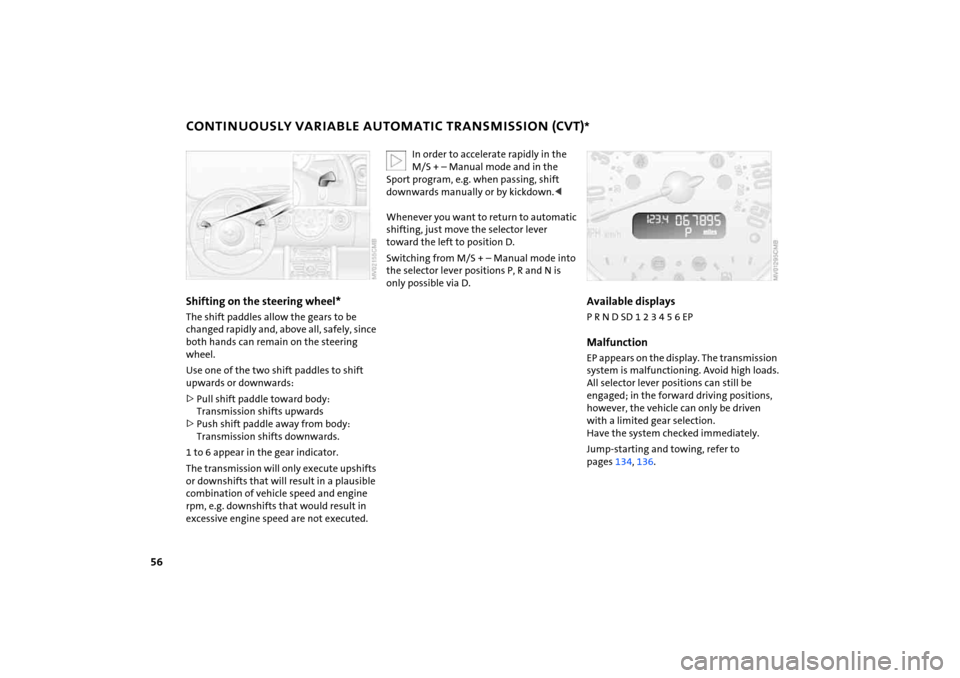
Shifting on the steering wheel* The shift paddles allow the gears to be
changed rapidly and, above all, safely, since
both hands can remain on the steering
wheel.Use one of the two shift paddles to shift
upwards or downwards:>Pull shift paddle toward body:
Transmission shifts upwards>Push shift paddle away from body:
Transmission shifts downwards.1 to 6 appear in the gear indicator.
The transmission will only execute upshifts
or downshifts that will result in a plausible
combination of vehicle speed and engine
rpm, e.g. downshifts that would result in
excessive engine speed are not executed.
In order to accelerate rapidly in the M/S
+ – Manual mode and in the
Sport program, e.g. when passing, shift
downwards manually or by kickdown.<
Whenever you want to return to automatic
shifting, just move the selector lever
toward the left to position D.Switching from M/S
+ – Manual mode into
the selector lever positions P, R and N is
only possible via D.
Available displaysP R N D SD 1 2 3 4 5 6 EPMalfunctionEP appears on the display. The transmission
system is malfunctioning. Avoid high loads.
All selector lever positions can still be
engaged; in the forward driving positions,
however, the vehicle can only be driven
with a limited gear selection.
Have the system checked immediately.Jump-starting and towing, refer to
pages
134
, 136
.
Page 65 of 165
63
OVERVIEW REPAIRS OPERATIONCONTROLS DATA INDEX
ODOMETER
CLOCK
FUEL GAUGE
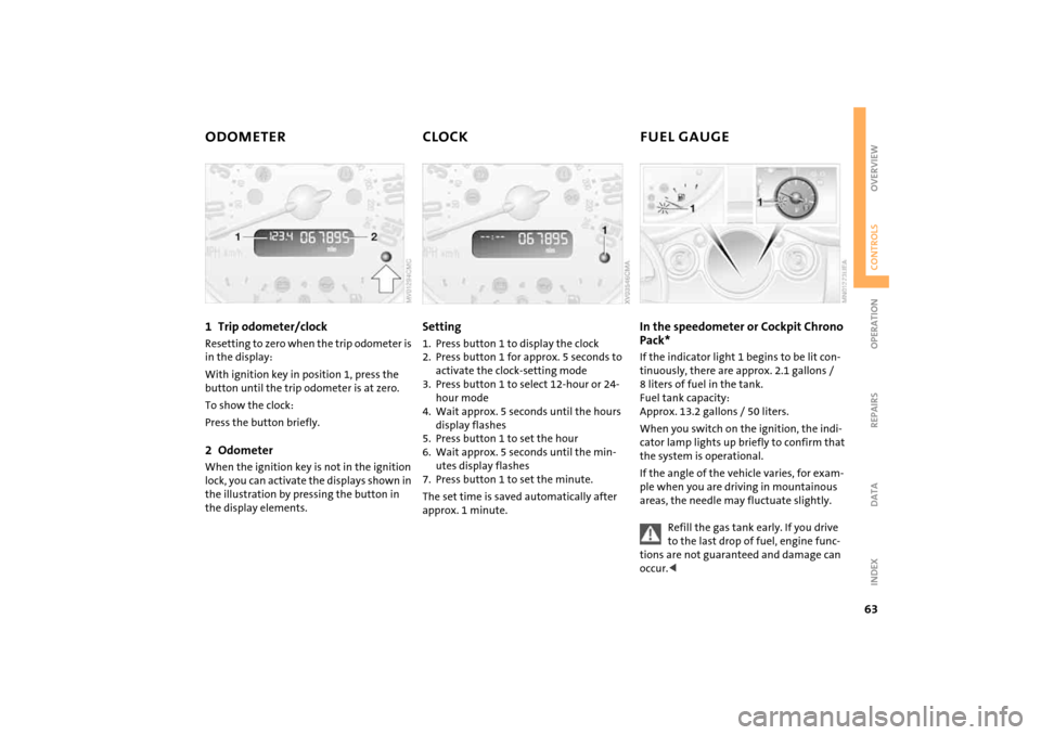
1 Trip odometer/clock
Resetting to zero when the trip odometer is
in the display:With ignition key in position
1, press the
button until the trip odometer is at zero.
To show the clock:Press the button briefly.2 Odometer
When the ignition key is not in the ignition
lock, you can activate the displays shown in
the illustration by pressing the button in
the display elements.
Setting 1. Press button
1 to display the clock
2. Press button
1 for approx. 5
seconds to
activate the clock-setting mode
3. Press button
1 to select 12-hour or 24-
hour mode
4. Wait approx. 5
seconds until the hours
display flashes
5. Press button
1 to set the hour
6. Wait approx. 5
seconds until the min
-
utes display flashes
7. Press button
1 to set the minute.
The set time is saved automatically after
approx. 1
minute.
In the speedometer or Cockpit Chrono Pack* If the indicator light
1 begins to be lit con
-
tinuously, there are approx. 2.1
gallons
/
8
liters of fuel in the tank.
Fuel tank capacity:
Approx. 13.2
gallons
/ 50
liters.
When you switch on the ignition, the indi
-
cator lamp lights up briefly to confirm that
the system is operational. If the angle of the vehicle varies, for exam
-
ple when you are driving in mountainous
areas, the needle may fluctuate slightly.
Refill the gas tank early. If you drive to the last drop of fuel, engine func
-
tions are not guaranteed and damage can
occur.<
Page 67 of 165

65
OVERVIEW REPAIRS OPERATIONCONTROLS DATA INDEX
TACHOMETER
SERVICE INTERVAL DISPLAY
Do not operate the engine with the needle in the red overspeed zone of the gauge.To protect the engine, the power is reduced
when you approach a certain engine speed
in this sector.
Remaining distance for serviceThe distance remaining before the next
scheduled service is displayed in miles
/
kilometers for a short period with the igni
-
tion key in position 1 or higher. The display
also indicates whether an engine oil service
and/or an inspection is due.
The onboard computer bases its calcula
-
tions of the remaining distance on your
driving style in the period immediately pre
-
ceding your data request. The remaining
distance display counts backwards in steps
of 35
miles / 50
km to the next service. A
flashing message and a minus sign in front
of the display that again begins counting
forwards mean that the service interval has
been exceeded.
Please schedule an appointment with your
MINI Dealer or a workshop that has spe
-
cially trained personnel working in accor
-
dance with the specifications of your MINI
manufacturer.For more information on the service inter
-
val display, refer to page
112
.
Page 68 of 165
66
ONBOARD COMPUTER
*
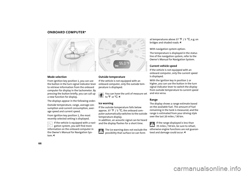
Mode selectionFrom ignition key position
1, you can use
the button in the turn signal indicator lever
to retrieve information from the onboard
computer for display in the tachometer. By
pressing the button briefly, you can call up
a new function for display.
The displays appear in the following order:Outside temperature, range, average con
-
sumption and current consumption, aver
-
age speed and current speed.From ignition key position
1, the most
recently selected setting is displayed.
If the vehicle is equipped with a navi
-
gation system, you will find more
information on the onboard computer in
the Owner's Manual for Navigation Sys
-
tem.<
Outside temperature If the vehicle is not equipped with an
onboard computer, only the outside tem
-
perature is displayed.
You can have the unit of measure set to 7 or
6.<
Ice warning If the outside temperature falls below
approx. 37
7 / 3
6, the onboard com
-
puter automatically switches to the outside
temperature display.
In addition, an acoustic signal can be heard
and the display flashes for a short time.
The ice warning does not exclude the possibility that surface ice can form
at temperatures above 37
7 / 3
6, e.g. on
bridges and shaded roads.<
With navigation system option:The temperature is displayed in the status
line of the navigation system, refer to the
Owner's Manual for Navigation System.Current vehicle speedIf the vehicle is not equipped with an
onboard computer, only the current speed
is displayed.With the ignition key in position
1 or
higher, you can use the button in the turn
signal indicator lever to switch the display
from outside temperature to current speed
and vice versa.
RangeThe display shows a range estimate based
on the available fuel. The amount of fuel
remaining in the tank is measured, and the
range is estimated from your driving style
over the last 20
miles
/ 30 km.
If the range displayed is less than 35 miles
/ 50 km, be sure to refuel;
otherwise engine functions are not guaran
-
teed and damage could occur.<
Page 69 of 165
67
OVERVIEW REPAIRS OPERATIONCONTROLS DATA INDEX
ONBOARD COMPUTER
*
Average speed, average fuel
consumption Press the button in the turn signal indicator
lever for a longer period.The displayed average values for speed and
consumption are recalculated.Any time spent with the vehicle stationary
and the engine shut off is ignored for the
calculation.
If the vehicle is equipped with a navi
-
gation system, the displays are
shown in the area of the navigation sys
-
tem.<
You can have a different unit of mea
-
sure set.<
Current fuel consumptionThe current consumption value is calcu
-
lated and displayed on the basis of your
driving style.
You can have a different unit of mea
-
sure set.<
Page 73 of 165
71
OVERVIEW REPAIRS OPERATIONCONTROLS DATA INDEX
FLAT TIRE MONITOR The conceptAs you drive, the Flat Tire Monitor keeps
track of the tire inflation pressure in all four
tires. The system alerts you when there is a
substantial pressure loss in one of the tires
relative to another.The tire inflation pressures are monitored
based on the speeds of the four wheels in
relation to one another. A flat tire is
detected as the result of differences in cer
-
tain speed ratios, and a warning is gener
-
ated.System requirementsSo that the system can 'familiarize' itself
with the correct inflation pressure, please
do the following:1. Check the tire inflation pressure in all
tires2. Compare them with the inflation pres
-
sure table, refer to page
98, and adjust
the pressures if necessary
3. Initialize the system.
System limitations
The Flat Tire Monitor cannot alert you to severe and sudden tire damage
caused by external factors, nor does it
detect the gradual and minor loss of pres
-
sure in all four tires.
-
sure loss or to the system not functioning:>Driving on snow-covered or slippery
roads>Performance-oriented driving: slip at the
drive wheels, high rates of lateral accel
-
eration>When driving with snow chains, false
warnings and undetected pressure loss
may occur>When driving with a space-saver spare
tire, the Flat Tire Monitor cannot func
-
tion.
Initializing the system
The system must be reinitialized immediately after changing a tire
and wheel, or after correcting the pressure
in any tire. This requires a bit of driving.<
1. Before a journey, start the engine, but do
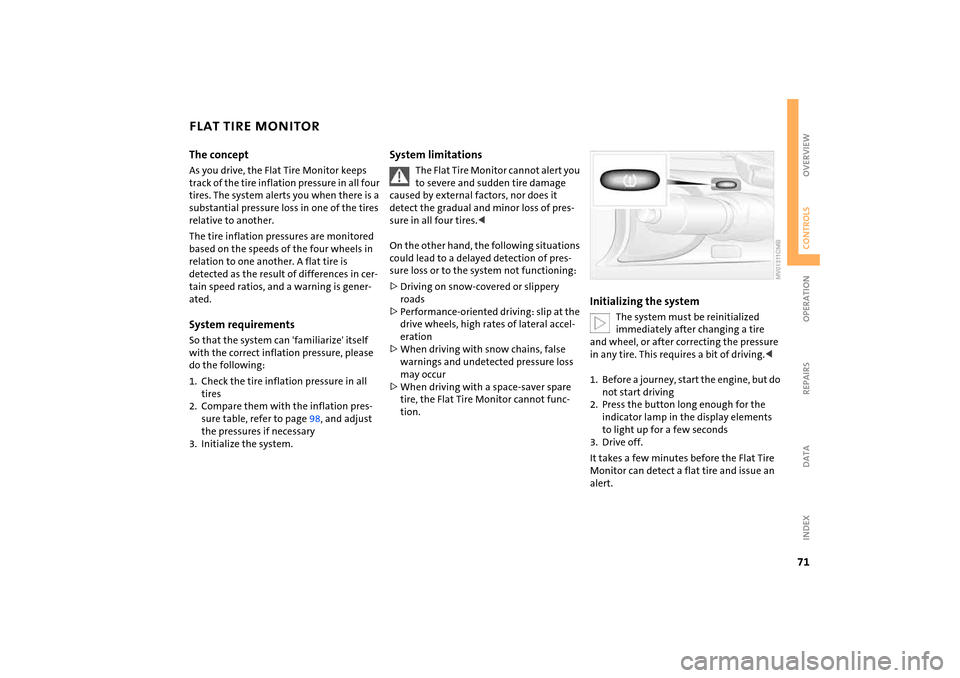
not start driving2. Press the button long enough for the
indicator lamp in the display elements
to light up for a few seconds3. Drive off.It takes a few minutes before the Flat Tire
Monitor can detect a flat tire and issue an
alert.
Page 75 of 165

73
OVERVIEW REPAIRS OPERATIONCONTROLS DATA INDEX
AIRBAGSProtective effectThe front airbags supplement the safety
belts by providing additional protection for
the driver and front passenger in the event
of a frontal collision in which the protec
-
tion afforded by the belts alone may no
longer be sufficient. When needed, the
head and side airbags help to furnish pro
-
tection in the event of side impact. Each of
the side airbags is designed to help support
the seat occupant's upper body. The corre
-
sponding side/head airbag in the MINI Con
-
vertible or the head airbag in the MINI sup
-
ports the head.The airbags are designed to not be trig
-
gered in certain types of collisions, e.g. in
minor accidents, certain kinds of vehicle
rollover and rear impact.For information on the ideal seating posi
-
tion, refer to page
41.
Do not apply adhesive materials to the cover panels of the airbags, cover
them or modify them in any other way. Do
not fit covers, cushions or other items to
the front seats that have not been specially
approved for seats with side airbags. Do
not hang clothing, e.
g. jackets, over the
backrests.
Do not attempt to remove the airbag
restraint system from the vehicle. Do not
touch the individual components directly
after the system has been triggered, as oth
-
erwise there is a danger of burns. In the
event of malfunctions, deactivation or
deployment of the airbag restraint system,
have the system checked, repaired or disas
-
sembled only by a MINI Dealer or a work
-
shop with specially trained personnel work
-
ing in accordance with the specifications of
the MINI manufacturer and having the nec
-
essary permits for handling explosive
devices. Unprofessional attempts to service
the system could lead to failure in an emer
-
gency or undesired airbag activation, either
of which could result in personal injury.
vided on the sun visors.Airbag system operational
The warning lamp in the display elements shows the status of the
entire airbag system and the seat
belt tensioners starting from ignition key
position 1. The warning lamp goes out after
several seconds.
Airbag system malfunctioning >The warning lamp does not come on
starting from ignition key position
1
>The warning lamp stays lit>The warning lamp lights up while driv
-
ing.
In the event of a malfunction, have the airbag system checked immedi
-
ately. Otherwise, there is a risk that the sys
-
tem will not function as intended in
response to a severe impact occurring
within the system's normal triggering
range.<
Page 80 of 165

78
1 Air onto the windshield and onto the
side windows2 Air for the upper body area
80
3 Air for the front and rear footwells4 Rear window defroster and windshield
heating
* 79
5 Interior temperature sensor, please keep
clear and unobstructed6 Recirculated air mode
79
7 Air conditioning
76
8 Automatic air distribution and
volume
79
9 Defrosting and demisting the windshield
and side windows
80
10 Temperature
79
11 Display for air temperature and air
volume
79
12 Air volume/Blower, switching air con
-
ditioner on/off
79
13 Individual air distribution
80
AUTOMATIC CLIMATE CONTROL
*
Page 81 of 165
79
OVERVIEW REPAIRS OPERATIONCONTROLS DATA INDEX
AUTOMATIC CLIMATE CONTROL
*
Automatic air distribution and volume
Automatic program (AUTO):
Indicator lamp lights up.
Automatic adjustment of the air distribu
-
tion and volume, and adaptation of the
specified temperatures to external influ
-
ences, i.e. outside temperature and sun
-
light.In the automatic program (AUTO), the air
conditioning is activated automatically. To
create a pleasant air climate, the air tem
-
perature coming from the vents in the
upper body area is lower than the air tem
-
perature in the footwell.Air volume/Blower
Switching automatic climate control
off/on
Air volume/Blower.
Press the left or right half of the
button. The air volume varies. Automatic
adjustment of the air volume is deacti
-
vated.Switching air conditioner on/off.
Press the left half of the button while the
blower is at the lowest setting. The blower,
heating and air conditioning are switched
off. All displays go out.
Switch the automatic climate control back
on by pressing any button.Air conditioning
Indicator lamp lights up.
The air is cooled and dehumidified
and, depending on the temperature set
-
ting, rewarmed.In the automatic program (AUTO), the air
conditioning is activated automatically. After the engine has started, the wind
-
shield can temporarily fog over. In the air
conditioning mode, there is less condensa
-
tion on the windows.
When the air conditioning is on, con
-
densation is formed which then exits
under the vehicle. Traces of condensed
water on the ground are therefore nor
-
mal.
-
cle is blocked. indicator lamp lights
up.
The air within the vehicle is recirculated.In the automatic program (AUTO) in hot
weather conditions, the recirculated air
mode is activated temporarily to enable
faster cooling.
The indicator lamp for the recirculated air
button is not lit.
The recirculated air mode should not be constantly used over a longer period of
time, as the air quality in the vehicle's interior
will otherwise gradually deteriorate. If the
windows fog up in the recirculated air mode,
turn the recirculated air mode off and if nec
-
essary increase the air supply.
<
Rear window defroster and windshield
heating*
Indicator lamp lights up.
As long as the indicator lamp is lit,
the window heater is operating.
The heater switches off automatically after a
short time. Temperature
Tap or turn the wheel in the appro
-
priate direction to change the tem
-
perature step by step.The figures in the display provide a
general indication of interior temperature.
When you start the vehicle, the system
ensures that the selected temperature is
achieved as quickly as possible and then main
-
tained.
Page 102 of 165
100
TIRE CODING
TIRE CONDITION
Traction The traction grades, from highest to low
-
est, are AA, A, B, and C.
Those grades represent the tire's ability to
stop on wet pavement as measured under
controlled conditions on specified govern
-
ment test surfaces of asphalt and concrete.
A tire marked C may have poor traction per
-
formance.
The traction grade assigned to this tire is based on straight-ahead brak
-
ing traction tests, and does not include
acceleration, cornering, hydroplaning, or
peak traction characteristics.
to the generation of heat and its ability to
dissipate heat when tested under con
-
trolled conditions on a specified indoor lab
-
oratory test wheel.
Sustained high temperature can cause the
material of the tire to degenerate and
reduce tire life, and excessive temperature
can lead to sudden tire failure. The grade C
corresponds to a level of performance
which all passenger car tires must meet
under the Federal Motor Vehicle Safety
Standard No. 109. Grades B and A represent
higher levels of performance on the labora
-
tory test wheel than the minimum required
by law.
The temperature grade for this tire is established for a tire that is properly
inflated and not overloaded. Excessive
speed, underinflation, or excessive loading,
either separately or in combination, can
cause heat buildup and possible tire fail
-
ure.
lar symbol containing the letters RSC on
the side of the tire, refer to page
101
.
M+SWinter and all-season tires.
These have better winter performance
properties than summer tires.
Inspect your tires frequently for tread wear,
signs of damage and for foreign objects
lodged in the tread. Check the tread depth.Tire tread The tread depth should not fall below
ε in / 3 mm.
Below ε
in / 3 mm tread depth, there is a
very high danger of hydroplaning at higher
speeds even if there is only a small amount
of water on the road.
Below a tread depth of
1/6 in / 4 mm, win
-
ter tires display a perceptible decrease in
their ability to cope with winter driving
conditions, and should be replaced in the
interest of safety.