display MINI Hardtop 2 Door 2006 User Guide
[x] Cancel search | Manufacturer: MINI, Model Year: 2006, Model line: Hardtop 2 Door, Model: MINI Hardtop 2 Door 2006Pages: 168, PDF Size: 2.22 MB
Page 59 of 168

57
OVERVIEW REPAIRS OPERATIONCONTROLS DATA INDEX
AUTOMATIC TRANSMISSION WITH STEPTRONIC*
Kickdown
Kickdown can be used to achieve maxi-
mum vehicle performance.
Press the accelerator pedal past the
increased resistance point at the full-throt-
tle position.
Available displays
P R N D SD M1 to M6 EP
M/S + – Manual mode and Sport
program
Switch from D into M/S + –:
This activates the Sport program and dis-
plays SD in the gear indicator in the speed-
ometer.
Press selector lever once:
This switches from the Sport program to
the manual mode.
In order to accelerate rapidly in the
M/S + – Manual mode and in the
Sport program, e.g. when passing, shift
downwards manually or by kickdown.<
Whenever you want to return to automatic
shifting, just move the selector lever
toward the left to position D.
Page 60 of 168

58
AUTOMATIC TRANSMISSION WITH STEPTRONIC*
Switching from M/S + – Manual mode into
the selector lever positions P, R and N is
only possible via D.
Shifting with the selector lever
>Press selector lever briefly towards +:
Transmission shifts upwards
>Press selector lever briefly towards –:
Transmission shifts downwards.
M1 to M6 appear in the gear indicator.
Shifting on the steering wheel*
The shift paddles allow the gears to be
changed rapidly and, above all, safely, since
both hands can remain on the steering
wheel.
To shift up or down with one of the two
shift paddles:
>Pull the shift paddle:
Transmission shifts up
>Press the shift paddle:
Transmission shifts down.
M1 to M6 appear in the gear indicator.
The transmission will only execute upshifts
or downshifts that will result in a plausible
combination of vehicle speed and engine
rpm, e.g. downshifts that would result in
excessive engine speed are not executed.
In the MINI COOPER S, with the selec-
tor lever in position D, automatic
mode, you can shift gears using the shift
paddles on the steering wheel. The trans-
mission automatically switches to manual
mode. If you do not shift gears with the
shift paddles or accelerate for a certain
amount of time, the transmission auto-
matically returns to automatic mode.<
Malfunction
EP appears on the display. The transmission
system is malfunctioning. Avoid high loads.
All selector lever positions can still be
engaged; in the forward driving positions,
however, the vehicle can only be driven
with a limited gear selection.
Have the system checked immediately.
Jump-starting and towing, refer to
page140 ff.
Page 68 of 168

66
ODOMETER CLOCK FUEL GAUGE
1 Trip odometer/clock
2Odometer
Trip odometer/clock
To switch between the trip odometer and
the clock:
Press the button.
To reset the trip odometer to zero:
Press the button until the trip odometer
shows zero.
To set the clock, refer to the information
below.
Odometer
When the ignition key is not in the ignition
lock, you can activate the displays shown in
the illustration by pressing the button in
the display elements.
Setting
The clock must be shown on the display.
1. If necessary, press button 1 to display
the clock
2. Press button 1 for approx. 5 seconds to
activate the clock-setting mode
3. Press button 1 to select 12-hour or
24-hour mode
4. Wait approx. 5 seconds until the hours
display is shown
5. Press button 1 to set the hour
6. Wait approx. 5 seconds until the min-
utes display is shown
7. Press button 1 to set the minute.
The time entered is stored automatically
after approx. 1 minute.
In the speedometer or Cockpit Chrono
Pack*
If the LED begins to be lit continuously,
there are approx. 2.1 gallons/8 liters of fuel
left in the tank.
Fuel tank capacity:
Approx. 13.2 gallons/50 liters.
When you switch on the ignition, the LED
lights up briefly to confirm that the system
is operational.
If the angle of the vehicle varies, for exam-
ple when you are driving in mountainous
areas, the needle may fluctuate slightly.
Refill the gas tank early. If you drive
to the last drop of fuel, engine func-
tions are not guaranteed and damage can
occur.<
Page 70 of 168

68
TACHOMETER SERVICE INTERVAL DISPLAY
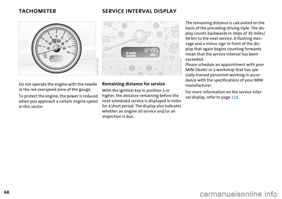
Do not operate the engine with the needle
in the red overspeed zone of the gauge.
To protect the engine, the power is reduced
when you approach a certain engine speed
in this sector.Remaining distance for service
With the ignition key in position 1 or
higher, the distance remaining before the
next scheduled service is displayed in miles
for a short period. The display also indicates
whether an engine oil service and/or an
inspection is due.
The remaining distance is calculated on the
basis of the preceding driving style. The dis-
play counts backwards in steps of 35 miles/
50 km to the next service. A flashing mes-
sage and a minus sign in front of the dis-
play that again begins counting forwards
mean that the service interval has been
exceeded.
Please schedule an appointment with your
MINI Dealer or a workshop that has spe-
cially trained personnel working in accor-
dance with the specifications of your MINI
manufacturer.
For more information on the service inter-
val display, refer to page118.
Page 71 of 168

69
OVERVIEW REPAIRS OPERATIONCONTROLS DATA INDEX
ONBOARD COMPUTER*
Mode selection
You can use the button in the turn signal
indicator lever to retrieve information from
the onboard computer for display in the
tachometer. By pressing the button briefly,
you can call up a new function for display.
The order of the displays:
Outside temperature, range, average con-
sumption and current consumption, aver-
age speed and current speed.
If the vehicle is equipped with a navi-
gation system, you will find more
information on the onboard computer in
the Owner's Manual for Navigation Sys-
tem.<
Outside temperature
If the vehicle is not equipped with an
onboard computer, only the outside tem-
perature is displayed.
Press the button in the turn indicator lever
to switch the display from outside temper-
ature to current speed and vice versa.
You can have the unit of measure set
to7 or6.<
Outside temperature warning
If the temperature falls to approx. +36/
377, the onboard computer automati-
cally switches to the outside temperature
display.
In addition, a signal sounds and the display
flashes.
Black ice can occur at temperatures
above +36/377 as well. You
should therefore drive carefully on bridges
and shaded roads, for example; as other-
wise there is an increased risk of an acci-
dent.<
With navigation system:
The temperature is displayed in the status
line of the navigation system, refer to the
Owner's Manual for Navigation System.
Current vehicle speed
If the vehicle is not equipped with an
onboard computer, only the current speed
is displayed.
Press the button in the turn indicator lever
to switch the display from outside temper-
ature to current speed and vice versa.
Range
The display shows a range estimate based
on the available fuel. The amount of fuel
remaining in the tank is measured, and the
range is estimated from your driving style
over the last 20 miles/30 km.
If the range displayed is less than
35 miles/50 km, be sure to refuel;
Page 72 of 168

70
ONBOARD COMPUTER*
otherwise engine functions are not guaran-
teed and damage could occur.<
Average speed, average fuel
consumption
To reset average consumption, average
speed:
Press the button in the turn signal indicator
lever for a long time.
The average consumption is determined
for the time during which the engine is run-
ning.
If the vehicle is equipped with a navi-
gation system, the displays are
shown in the area of the navigation sys-
tem.<
You can have a different unit of mea-
sure set.<
Current fuel consumption
Shows the current fuel consumption. You
can check how economically and environ-
mentally friendly you are currently driving.
You can have a different unit of mea-
sure set.<
Page 75 of 168

73
OVERVIEW REPAIRS OPERATIONCONTROLS DATA INDEX
FLAT TIRE MONITOR
The concept
As you drive, the Flat Tire Monitor keeps
track of the tire inflation pressure in all four
tires. The system alerts you when there is a
substantial pressure loss in one of the tires
relative to another.
In the event of tire pressure loss, the rolling
radius of the tire changes, thereby affect-
ing the rotational speed of the wheels. This
change is detected, and a flat tire warning
is issued to the driver.
System requirements
To ensure the reliability of flat tire warn-
ings, the system must be initialized with
the correct tire inflation pressures.
Each time you correct the pressure in
a tire, or change a wheel or tire, the
system must be reinitialized.<
System limitations
The Flat Tire Monitor cannot alert you
to severe and sudden tire damage
caused by external factors, nor does it
detect the gradual and minor loss of pres-
sure in all four tires.<
The system could issue a false warning or
function in a delayed manner in the follow-
ing situations:
>System was not initialized
>You are driving on a snow-covered or
slippery road surface
>Performance-oriented driving: slip at the
drive wheels, high rates of lateral accel-
eration
>You are driving with snow chains.
When driving with a space-saver spare tire,
the Flat Tire Monitor cannot function.
Initializing the system
Initialization is completed while you
are driving, but you can stop the car
at any time. Initialization is automatically
continued when you continue driving. Do
not initialize the system if you are driving
with snow chains or a space-saver spare
tire.<
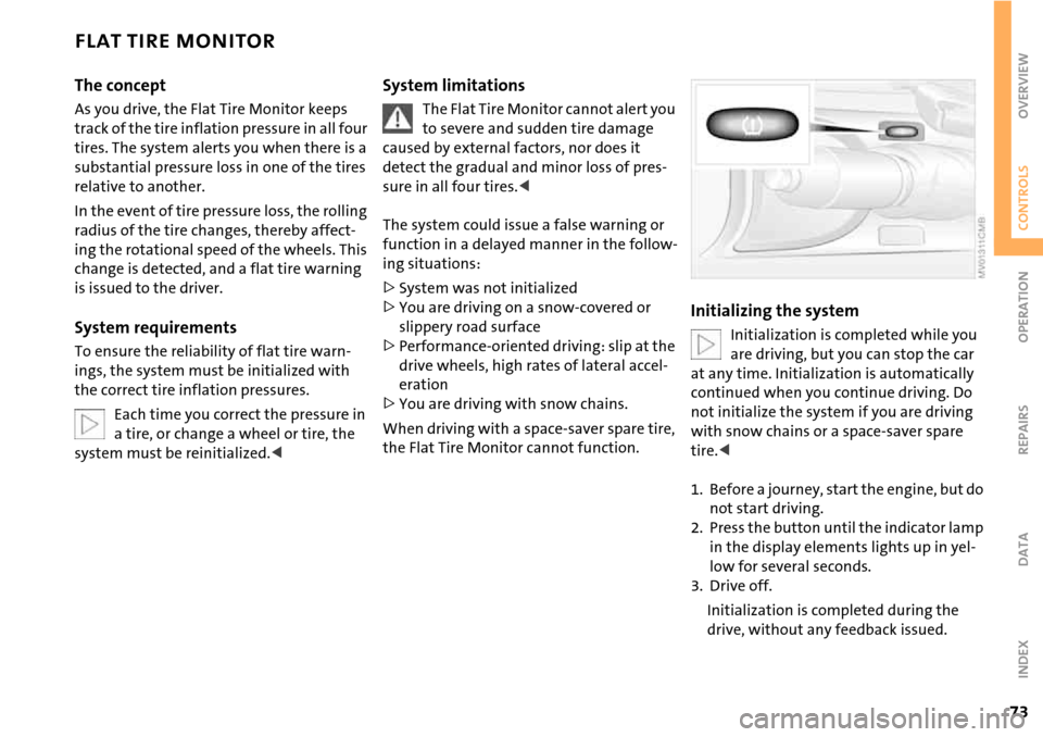
1. Before a journey, start the engine, but do
not start driving.
2. Press the button until the indicator lamp
in the display elements lights up in yel-
low for several seconds.
3. Drive off.
Initialization is completed during the
drive, without any feedback issued.
Page 78 of 168

76
AIRBAGS
tivated or activated, refer to Functional sta-
tus of the front passenger airbags below. <
Before transporting a child on the
front passenger seat, read the safety
notes and instructions under Transporting
children safely, refer to page50.
Adolescents and adults sitting in certain
positions could also deactivate the front
and side airbags for the front passenger;
the indicator lamp for the front passenger
airbags comes on. In such cases, the occu-
pant should change his or her sitting posi-
tion so that the front passenger airbags are
activated and the indicator lamp goes out.
If the airbags are not activated although
the seat occupant has changed his or her
position, have the occupant sit on a rear
seat. Do not attach covers, cushions, ball
mats or other items to the front passenger
seat unless they are specifically recom-
mended by the manufacturer of your MINI.
Do not place any objects under the seat
which could press against the seat from
below. Otherwise, a correct analysis of the
seat cushion is not ensured.<
Functional status of the front
passenger airbags
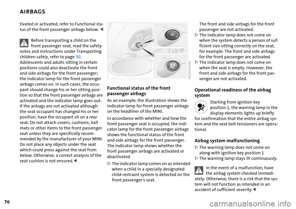
As an example, the illustration shows the
indicator lamp for front passenger airbags
on the headliner of the MINI.
In accordance with whether and how the
front passenger seat is occupied, the indi-
cator lamp for the front passenger airbags
shows the functional status of the front
and side airbags for the front passenger.
The indicator lamp shows whether the
front passenger airbags are activated or
deactivated.
>The indicator lamp comes on as intended
when a child in a specially designated
child-restraint system is detected on the
front passenger's seat.
The front and side airbags for the front
passenger are not activated.
>The indicator lamp does not come on
when the system detects a person of suf-
ficient size sitting correctly on the seat,
for example. The front and side airbags
for the front passenger are activated.
>The indicator lamp does not come on
when the seat is empty. However, the
front and side airbags for the front pas-
senger are not activated.
Operational readiness of the airbag
system
Starting from ignition key
position 1, the warning lamp in the
display elements lights up briefly
for confirmation that the entire airbag sys-
tem and the seat belt tensioners are opera-
tional.
Airbag system malfunctioning
>The warning lamp does not come on
along with ignition key position 1
>The warning lamp stays lit continuously.
In the event of a malfunction, have
the airbag system checked immedi-
ately. Otherwise, there is a risk that the sys-
tem will not function as intended in an
accident of sufficient severity.<
Page 83 of 168

81
OVERVIEW REPAIRS OPERATIONCONTROLS DATA INDEX
1Air onto the windshield and onto the
side windows
2 Air for the upper body area83
3 Air for the front and rear footwells
4 Rear window defroster and windshield
heating
*825 Interior temperature sensor, please keep
clear and unobstructed
6 Recirculated air mode82
7 Cooling function82
8 Automatic air distribution and
volume82
9 Defrosting and demisting the windshield
and side windows8310 Temperature82
11 Display for air temperature and air
volume82
12 Air volume/Blower, switching air con-
ditioner on/off82
13 Individual air distribution83
AUTOMATIC CLIMATE CONTROL*
Page 84 of 168

82
AUTOMATIC CLIMATE CONTROL*
Automatic air distribution and volume
The LED is lit when the AUTO pro-
gram is on.
Automatic adjustment of the air distribu-
tion and volume, and adaptation of the
specified temperatures to external influ-
ences, e.g. outside temperature and insola-
tion.
In the automatic program (AUTO), the air
conditioning is activated automatically. To
create a pleasant air climate, the air tem-
perature coming from the vents in the
upper body area is lower than the air tem-
perature in the footwell.
Air volume/Blower
Switching automatic climate control
off/on
Press the left or right half of the
button to vary the air volume.
Automatic adjustment of the air volume is
deactivated.
Switching air conditioner on/off.
Press the left half of the button while the
blower is at the lowest setting. The blower,
heating and air conditioning are switched
off. All displays go out.
Switch the automatic climate control back
on by pressing any button.
Cooling function
The LED is lit when the cooling
function is on.
The air is cooled and dehumidified and,
depending on the temperature setting,
rewarmed.
The cooling function is automatically acti-
vated in the AUTO program.
Depending on the weather, the windshield
can fog up temporarily after the engine is
started.
When the air conditioning is on, con-
densation is formed which then exits
under the vehicle. Traces of condensed
water on the ground are therefore nor-
mal.<
Recirculated air mode
The LED is lit when the recirculated
air mode is on. Supply of outside air
into the vehicle is blocked.
The air within the vehicle is recirculated.
In the automatic program (AUTO) in hot
weather conditions, the recirculated air
mode is activated temporarily to enable
faster cooling.
The LED for the recirculated air button is
not lit.
The recirculated air mode should not
be used constantly over a longer
period of time; otherwise the air quality in
the vehicle's interior will gradually deterio-
rate. If the windows fog up in the recircu-
lated air mode, turn the recirculated air
mode off and, if necessary, increase the air
supply.<
Rear window defroster and windshield
heating*
The LED comes on when the rear
window/windshield heating is on.
The heater switches off automatically after
a short time.
Temperature
Tap or turn the wheel in the
appropriate direction to change
the temperature step by step.
The figures in the display provide
a general indication of interior tempera-
ture. When you start the vehicle, the sys-
tem ensures that the selected temperature
is achieved as quickly as possible and then
maintained.
Permanent heating with maximum
power output at temperature selec-
tion HI. Permanent cooling at LO. With the