ECO mode MINI Hardtop 2 Door 2006 Owner's Manual
[x] Cancel search | Manufacturer: MINI, Model Year: 2006, Model line: Hardtop 2 Door, Model: MINI Hardtop 2 Door 2006Pages: 168, PDF Size: 2.22 MB
Page 9 of 168
7
OVERVIEW REPAIRS OPERATION CONTROLS DATA INDEX
Editorial notice
The manufacturer pursues a policy of con-
tinuous, ongoing development that is con-
ceived to ensure that MINI vehicles con-
tinue to embody the highest quality and
safety standards combined with advanced,
state-of-the-art technology. For this rea-
son, the features described in this Owner's
Manual could, in rare cases, differ from
those in your vehicle.
For your own safety
Fuels:
Use unleaded gasoline only. Fuels
containing up to and including 10 %
ethanol or other oxygenates with up to
2.8 % oxygen by weight, i.e. 15 % MTBE or
3 % methanol plus an equivalent amount of
co-solvent, will not void the applicable war-
ranties with respect to defects in materials
or workmanship. Field experience has indi-
cated significant differences in fuel quality,
i.e. volatility, composition, additives, etc.,
among gasolines offered for sale in the
United States and Canada. The use of
poor-quality fuels may result in driveabil-
ity, starting and stalling problems espe-
cially under certain environmental condi-
tions, such as high ambient temperature
and high altitude.
Should you encounter driveability prob-
lems which you suspect could be related to
the fuel you are using, we recommend that
you respond by switching to a recognized
high-quality brand.
Failure to comply with these recommenda-
tions may result in unscheduled mainte-
nance.
Obey pertinent safety rules when you are
handling gasoline.<
Maintenance and repair:
Advanced technology, e.g. the use of
modern materials and powerful elec-
tronics, requires specially adapted mainte-
nance and repair methods. Have the neces-
sary work on your MINI carried out by a
MINI Dealer or a workshop that has spe-
cially trained personnel working in accor-
dance with the specifications of the MINI
manufacturer. Work that is improperly car-
ried out could result in consequential dam-
age and pose safety hazards.
lowing warning.
Engine exhaust and a wide variety of
automobile components and parts,
including components found in the interior
furnishings in a vehicle, contain or emit
chemicals known to the State of California
to cause cancer and birth defects and
reproductive harm. In addition, certain flu-
ids contained in vehicles and certain prod-
ucts of component wear contain or emit
chemicals known to the State of California
to cause cancer and birth defects or other
reproductive harm.
Battery posts, terminals and related acces-
sories contain lead and lead compounds.
Batteries also contain other chemicals
known to the State of California to cause
cancer. Wash your hands after handling.
Used engine oil contains chemicals that
have caused cancer in laboratory animals.
Always protect your skin by washing thor-
oughly with soap and water.<
NOTES
Page 10 of 168
8
NOTES
Parts and accessories:
For your own safety, use genuine
parts and accessories approved by
the manufacturer of the MINI.
When you purchase accessories tested
and approved by the manufacturer of the
MINI and Original MINI Parts, you simulta-
neously acquire the assurance that they
have been thoroughly tested by the manu-
facturer of the MINI to ensure optimum
performance when installed on your vehi-
cle.
The manufacturer of the MINI warrants
these parts to be free from defects in mate-
rial and workmanship.
The manufacturer of the MINI will not
accept any liability for damages resulting
from installation of parts and accessories
not approved by the manufacturer
of the MINI.
The manufacturer of the MINI cannot test
every product from other manufacturers to
verify if it can be used on a MINI safely and
without risk to either the vehicle, its opera-
tion, or its occupants.
Original MINI Parts, MINI Accessories and
other products approved by the manufac-
turer of the MINI, together with profes-
sional advice on using these items, are
available from all MINI Dealers.
Installation and operation of non-MINI approved accessories such as alarms,
radios, amplifiers, radar detectors, wheels,
suspension components, brake dust
shields, telephones, including operation of
any portable cellular phone from within
the vehicle without using an externally
mounted antenna, or transceiver equip-
ment, e.g. CB, walkie-talkie, ham radio or
similar, may cause extensive damage to the
vehicle, compromise its safety, interfere
with the vehicle's electrical system or affect
the validity of the MINI Limited Warranty.
See your MINI Dealer for additional infor-
mation.<
Maintenance, replacement, or repair
of the emission control devices and
systems must be performed by an autho-
rized MINI Dealership or individual using
certified MINI parts.<
Symbol on vehicle parts
Indicates that you should consult the
relevant section of this Owner's Man-
ual for information on a particular part or
assembly.
Service and warranty
This manual is supplemented by a Service
and Warranty Information Booklet for US
models or a Warranty and Service Guide
Booklet for Canadian models.
We recommend that you read this publica-
tion thoroughly.
Your MINI is covered by the following war-
ranties:
>New Vehicle Limited Warranty
>Rust Perforation Limited Warranty
>Federal Emissions System Defect War-
ranty
>Federal Emissions Performance War-
ranty
>California Emission Control System Lim-
ited Warranty.
Detailed information about these warran-
ties is listed in the Service and Warranty
Information Booklet for US models or in the
Warranty and Service Guide Booklet for
Canadian models.
Page 19 of 168
17
OVERVIEW REPAIRS OPERATION CONTROLS DATA INDEX
INDICATOR AND WARNING LAMPS
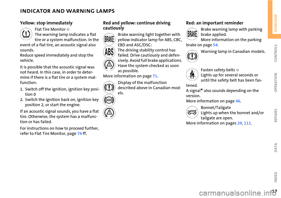
Yellow: stop immediately
Flat Tire Monitor +
The warning lamp indicates a flat
tire or a system malfunction. In the
event of a flat tire, an acoustic signal also
sounds.
Reduce speed immediately and stop the
vehicle.
It is possible that the acoustic signal was
not heard. In this case, in order to deter-
mine if there is a flat tire or a system mal-
function:
1. Switch off the ignition, ignition key posi-
tion 0
2. Switch the ignition back on, ignition key
position 2, or start the engine.
If an acoustic signal sounds, you have a flat
tire. Otherwise, the system has a malfunc-
tion or has failed.
For instructions on how to proceed further,
refer to Flat Tire Monitor, page74 ff.
Red and yellow: continue driving
cautiously
Brake warning light together with
yellow indicator lamp for ABS, CBC,
EBD and ASC/DSC:
The driving stability control has
failed. Drive cautiously and defen-
sively. Avoid full brake applications.
Have the system checked as soon
as possible.
More information on page71.
Display of the malfunction
described above in Canadian mod-
els.
Red: an important reminder
Brake warning lamp with parking
brake applied.
More information on the parking
brake on page54.
Warning lamp in Canadian models.
Fasten safety belts
+
Lights up for several seconds or
until the safety belt has been fas-
tened.
A signal
* also sounds depending on the
version.
More information on page46.
Bonnet/Tailgate
Lights up when the bonnet and/or
tailgate are open.
More information on pages29, 111.
Page 28 of 168
26
OPENING AND CLOSING: FROM OUTSIDE
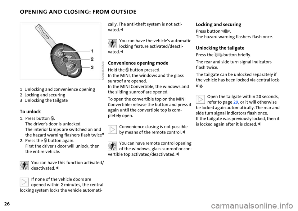
1 Unlocking and convenience opening
2 Locking and securing
3 Unlocking the tailgate
To unlock
1. Press button .
The driver's door is unlocked.
The interior lamps are switched on and
the hazard warning flashers flash twice
*
2. Press the button again.
First the driver's door will unlock, then
the entire vehicle.
You can have this function activated/
deactivated.<
If none of the vehicle doors are
opened within 2 minutes, the central
locking system locks the vehicle automati-
cally. The anti-theft system is not acti-
vated.<
You can have the vehicle's automatic
locking feature activated/deacti-
vated.<
Convenience opening mode
Hold the button pressed.
In the MINI, the windows and the glass
sunroof are opened.
In the MINI Convertible, the windows and
the sliding sunroof are opened.
To open the convertible top on the MINI
Convertible: release the button and press it
again until the convertible top is com-
pletely open.
Convenience closing is not possible
by means of the remote control.<
You can have remote control opening
of the windows, glass sunroof or con-
vertible top activated/deactivated.<
Locking and securing
Press button .
The hazard warning flashers flash once.
Unlocking the tailgate
Press the button briefly.
The rear and side turn signal indicators
flash twice.
The tailgate can be unlocked separately if
the vehicle has been locked via central lock-
ing.
Open the tailgate within 20 seconds,
refer to page29, or it will otherwise
be locked again automatically. The rear and
side turn signal indicators flash once.
If the tailgate was previously locked, then it
is locked again after it is closed.<
Page 41 of 168

39
OVERVIEW REPAIRS OPERATIONCONTROLS DATA INDEX
CONVERTIBLE TOP WITH INTEGRATED SLIDING SUNROOF
Releasing the convertible top
Depending on the vehicle model, it
may also be necessary to release the
convertible top in order to close it.<
1. Press the lever with the hexagon wrench
to release the convertible top, see arrow
1, and lift the side frame, see arrow 2.
If necessary, insert an object between
that side frame and the body to prevent
the convertible top from locking again
2. Release the second side frame.
Closing the convertible top
If possible, close the convertible top
with the help of a second person.<
1. Place both hands on the convertible top
on the respective side frame
2. Lift out both sides at the same time, and
swing the convertible top forward onto
the cowl
3. Inside the vehicle, use a screwdriver to
pry out the cover in the center of the
roof.
To close the sliding sunroof
1. Insert the hexagon wrench into the des-
ignated socket in the middle of the roof
2. Knock the hexagon wrench in the direc-
tion of arrow 1 to uncouple the sliding
sunroof mechanism. The hexagon
wrench moves upwards
3. Turn the hexagon wrench in the direc-
tion of arrow 2.
To lock the convertible top
Continue to turn the hexagon wrench until
the convertible top is locked in place.
Please contact your MINI Dealer to
have the electrical malfunction
repaired.<
Page 55 of 168
53
OVERVIEW REPAIRS OPERATIONCONTROLS DATA INDEX
IGNITION LOCK STARTING THE ENGINE
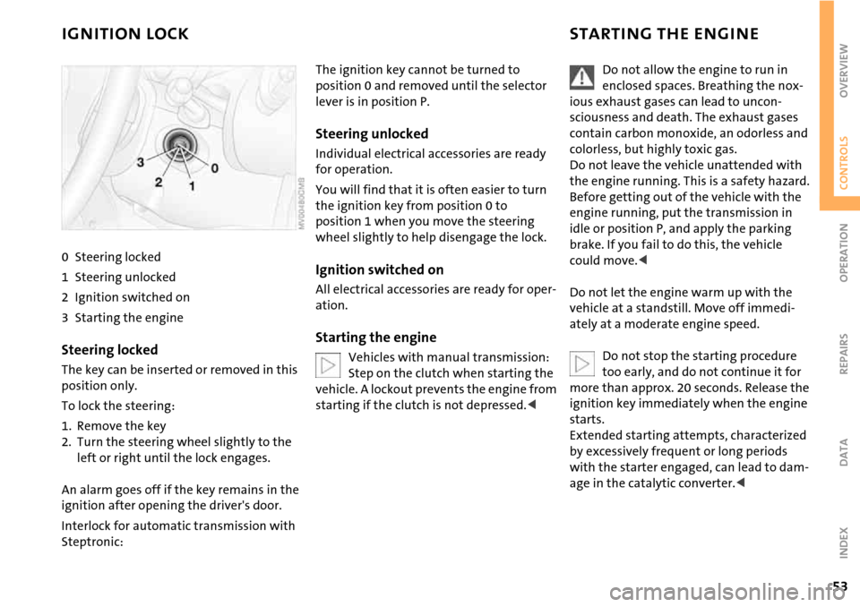
0 Steering locked
1 Steering unlocked
2 Ignition switched on
3 Starting the engine
Steering locked
The key can be inserted or removed in this
position only.
To lock the steering:
1. Remove the key
2. Turn the steering wheel slightly to the
left or right until the lock engages.
An alarm goes off if the key remains in the
ignition after opening the driver's door.
Interlock for automatic transmission with
Steptronic:
The ignition key cannot be turned to
position 0 and removed until the selector
lever is in position P.
Steering unlocked
Individual electrical accessories are ready
for operation.
You will find that it is often easier to turn
the ignition key from position 0 to
position 1 when you move the steering
wheel slightly to help disengage the lock.
Ignition switched on
All electrical accessories are ready for oper-
ation.
Starting the engine
Vehicles with manual transmission:
Step on the clutch when starting the
vehicle. A lockout prevents the engine from
starting if the clutch is not depressed.<
Do not allow the engine to run in
enclosed spaces. Breathing the nox-
ious exhaust gases can lead to uncon-
sciousness and death. The exhaust gases
contain carbon monoxide, an odorless and
colorless, but highly toxic gas.
Do not leave the vehicle unattended with
the engine running. This is a safety hazard.
Before getting out of the vehicle with the
engine running, put the transmission in
idle or position P, and apply the parking
brake. If you fail to do this, the vehicle
could move.<
Do not let the engine warm up with the
vehicle at a standstill. Move off immedi-
ately at a moderate engine speed.
Do not stop the starting procedure
too early, and do not continue it for
more than approx. 20 seconds. Release the
ignition key immediately when the engine
starts.
Extended starting attempts, characterized
by excessively frequent or long periods
with the starter engaged, can lead to dam-
age in the catalytic converter.<
Page 68 of 168

66
ODOMETER CLOCK FUEL GAUGE
1 Trip odometer/clock
2Odometer
Trip odometer/clock
To switch between the trip odometer and
the clock:
Press the button.
To reset the trip odometer to zero:
Press the button until the trip odometer
shows zero.
To set the clock, refer to the information
below.
Odometer
When the ignition key is not in the ignition
lock, you can activate the displays shown in
the illustration by pressing the button in
the display elements.
Setting
The clock must be shown on the display.
1. If necessary, press button 1 to display
the clock
2. Press button 1 for approx. 5 seconds to
activate the clock-setting mode
3. Press button 1 to select 12-hour or
24-hour mode
4. Wait approx. 5 seconds until the hours
display is shown
5. Press button 1 to set the hour
6. Wait approx. 5 seconds until the min-
utes display is shown
7. Press button 1 to set the minute.
The time entered is stored automatically
after approx. 1 minute.
In the speedometer or Cockpit Chrono
Pack*
If the LED begins to be lit continuously,
there are approx. 2.1 gallons/8 liters of fuel
left in the tank.
Fuel tank capacity:
Approx. 13.2 gallons/50 liters.
When you switch on the ignition, the LED
lights up briefly to confirm that the system
is operational.
If the angle of the vehicle varies, for exam-
ple when you are driving in mountainous
areas, the needle may fluctuate slightly.
Refill the gas tank early. If you drive
to the last drop of fuel, engine func-
tions are not guaranteed and damage can
occur.<
Page 101 of 168
99
OVERVIEW REPAIRSOPERATIONCONTROLS DATA INDEX
REFUELING
Always switch off the engine before
refueling; otherwise no fuel can be
added to the tank and the SERVICE ENGINE
SOON lamp may come on.<
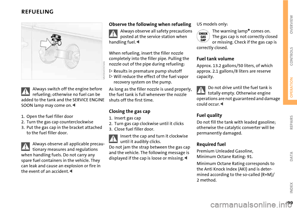
1. Open the fuel filler door
2. Turn the gas cap counterclockwise
3. Put the gas cap in the bracket attached
to the fuel filler door.
Always observe all applicable precau-
tionary measures and regulations
when handling fuels. Do not carry any
spare fuel containers in the vehicle. They
can leak and cause an explosion or fire in
the event of an accident.<
Observe the following when refueling
Always observe all safety precautions
posted at the service station when
handling fuel.<
When refueling, insert the filler nozzle
completely into the filler pipe. Pulling the
nozzle out of the pipe during refueling:
>Results in premature pump shutoff
>Will reduce the effect of the fuel vapor
recovery system on the pump.
As long as the filler nozzle is used properly,
the fuel tank is full whenever the nozzle
shuts off the first time.
Closing the gas cap
1. Insert gas cap
2. Turn gas cap clockwise until it clicks
3. Close fuel filler door.
Insert the cap and turn it clockwise
until it audibly clicks.
Do not jam the strap between the gas cap
and the vehicle. The following message is
displayed if the cap is loose or missing.<
US models only:
The warning lamp
* comes on.
The gas cap is not correctly closed
or missing. Check if the gas cap is
correctly closed.
Fuel tank volume
Approx. 13.2 gallons/50 liters, of which
approx. 2.1 gallons/8 liters are reserve
capacity.
Do not drive until the fuel tank is
totally empty. Otherwise engine
operations are not guaranteed and damage
could occur.<
Fuel quality
Do not fill the tank with leaded gasoline;
otherwise the catalytic converter will be
permanently damaged.
Required fuel
Premium Unleaded Gasoline,
Minimum Octane Rating: 91.
Minimum Octane Rating corresponds to
the Anti Knock Index (AKI) and is deter-
mined according to the so-called (R+M)/
2method.
Page 111 of 168

109
OVERVIEW REPAIRSOPERATIONCONTROLS DATA INDEX
NEW WHEELS AND TIRES
The correct wheels and tires
The manufacturer of your MINI rec-
ommends mounting only wheels and
tires that it has specifically approved for
use on your particular model. Although
other wheels and tires may theoretically
have the same dimensions, variations in
factors such as manufacturing tolerances
can result in contact between tire and
bodywork, ultimately leading to serious
accidents. The manufacturer of your MINI
cannot evaluate non-approved wheels and
tires to determine if they are suited for use,
and therefore cannot ensure the operating
safety of the vehicle if they are mounted.<
Your MINI Dealer will be glad to inform you
about the correct wheel and tire combina-
tion for your vehicle.
The correct wheel and tire combination is
also important for various systems that
would otherwise be impaired, e.g. ABS or
DSC.
To maintain good handling and vehicle
response, use only tires of a single brand
and tread configuration. In the event of tire
damage, remount the previous wheel and
tire combination as soon as possible.
Run Flat tires
For your own safety, use Run Flat tires
when mounting new tires or replacing
summer tires with winter tires or vice
versa. Keep in mind that no spare wheel is
available in the event of a flat. Your MINI
Dealer will be glad to advise you.
For safety reasons, the manufacturer
of your MINI recommends having
Run Flat tires replaced, not repaired, if they
are damaged.<
Tire designation
For each tire size, the manufacturer of your
MINI recommends certain tire brands. You
can recognize these by the clearly visible
designation on the tire's sidewall.
When used properly these tires meet the
highest standards regarding safety and
handling characteristics.
Page 119 of 168
117
OVERVIEW REPAIRSOPERATIONCONTROLS DATA INDEX
BRAKE SYSTEM
Brake fluid level
The warning lamp comes on
although the parking brake is
released:
The brake fluid level in the reservoir is too
low, refer to page16. At the same time,
brake pedal travel may become signifi-
cantly longer.
Have the system checked immediately.
If the brake fluid level is too low and brake
pedal travel has become longer, there may
be a defect in one of the brake system's
hydraulic circuits.
Display of the malfunction
described above in Canadian mod-
els.
If you continue driving, higher brake
application pressure may be neces-
sary, and there may be a slight pull to one
side. Brake pedal travel may also be longer.
Please remember to adapt your driving
style accordingly.<
Brake pads
Brake pad sensors in the left brake pads of
the front axle and in the right brake pads of
the rear axle monitor the brake pad condi-
tion. When the brake pads reach the wear
limit, the brake wear warning lights up,
refer to page18.
Use brake pads which the manufac-
turer of your MINI has approved for
your particular vehicle model. The manu-
facturer of your MINI cannot evaluate non-
approved brake pads to determine if they
are suitable for use, and therefore cannot
ensure the operating safety of the vehicle
in the event of their use.<