ECU MINI Hardtop 2 Door 2015 Owner's Manual (Mini Connected)
[x] Cancel search | Manufacturer: MINI, Model Year: 2015, Model line: Hardtop 2 Door, Model: MINI Hardtop 2 Door 2015Pages: 244, PDF Size: 11.11 MB
Page 32 of 244

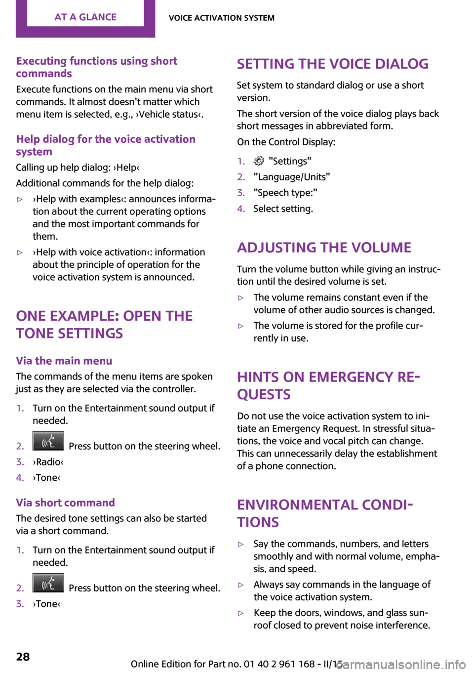
Executing functions using short
commands
Execute functions on the main menu via short
commands. It almost doesn't matter which
menu item is selected, e.g., ›Vehicle status‹.
Help dialog for the voice activation
system
Calling up help dialog: ›Help‹
Additional commands for the help dialog:▷›Help with examples‹: announces informa‐
tion about the current operating options
and the most important commands for
them.▷›Help with voice activation‹: information
about the principle of operation for the
voice activation system is announced.
One example: open the
tone settings
Via the main menu
The commands of the menu items are spoken
just as they are selected via the controller.
1.Turn on the Entertainment sound output if
needed.2. Press button on the steering wheel.3.›Radio‹4.›Tone‹
Via short command
The desired tone settings can also be started
via a short command.
1.Turn on the Entertainment sound output if
needed.2. Press button on the steering wheel.3.›Tone‹Setting the voice dialog
Set system to standard dialog or use a short
version.
The short version of the voice dialog plays back short messages in abbreviated form.
On the Control Display:1. "Settings"2."Language/Units"3."Speech type:"4.Select setting.
Adjusting the volume
Turn the volume button while giving an instruc‐
tion until the desired volume is set.
▷The volume remains constant even if the
volume of other audio sources is changed.▷The volume is stored for the profile cur‐
rently in use.
Hints on Emergency Re‐
quests
Do not use the voice activation system to ini‐
tiate an Emergency Request. In stressful situa‐
tions, the voice and vocal pitch can change.
This can unnecessarily delay the establishment
of a phone connection.
Environmental condi‐
tions
▷Say the commands, numbers, and letters
smoothly and with normal volume, empha‐
sis, and speed.▷Always say commands in the language of
the voice activation system.▷Keep the doors, windows, and glass sun‐
roof closed to prevent noise interference.Seite 28AT A GLANCEVoice activation system28
Online Edition for Part no. 01 40 2 961 168 - II/15
Page 35 of 244

Scroll forward.
Context help - Owner's Manual to the
temporarily selected function
You may open the relevant information di‐
rectly.
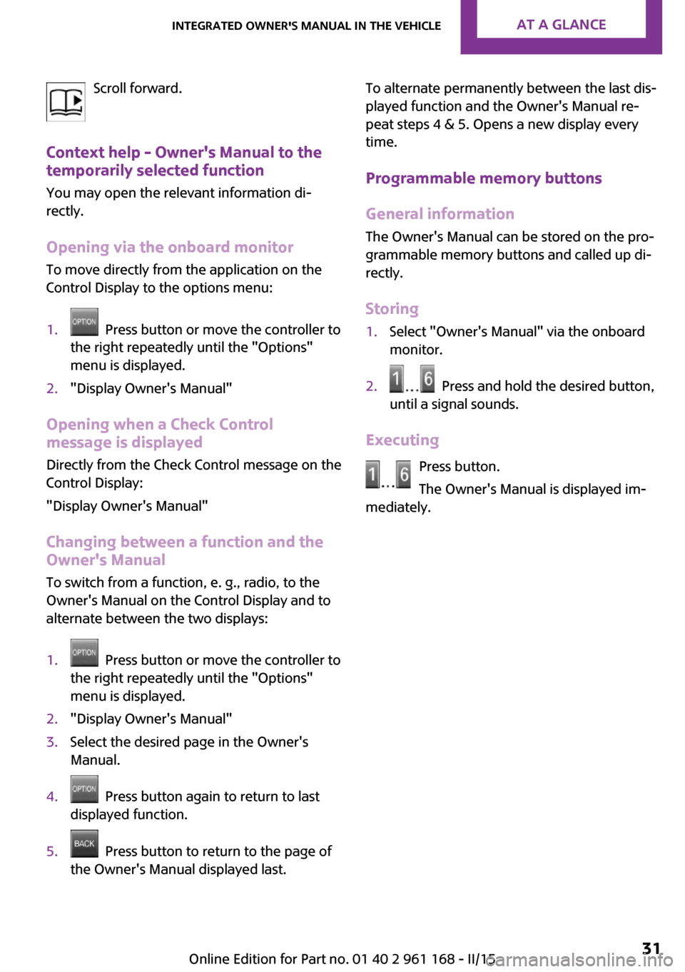
Opening via the onboard monitor To move directly from the application on theControl Display to the options menu:1. Press button or move the controller to
the right repeatedly until the "Options"
menu is displayed.2."Display Owner's Manual"
Opening when a Check Control
message is displayed
Directly from the Check Control message on the
Control Display:
"Display Owner's Manual"
Changing between a function and the
Owner's Manual
To switch from a function, e. g., radio, to the
Owner's Manual on the Control Display and to
alternate between the two displays:
1. Press button or move the controller to
the right repeatedly until the "Options"
menu is displayed.2."Display Owner's Manual"3.Select the desired page in the Owner's
Manual.4. Press button again to return to last
displayed function.5. Press button to return to the page of
the Owner's Manual displayed last.To alternate permanently between the last dis‐
played function and the Owner's Manual re‐
peat steps 4 & 5. Opens a new display every
time.
Programmable memory buttons
General information The Owner's Manual can be stored on the pro‐
grammable memory buttons and called up di‐
rectly.
Storing1.Select "Owner's Manual" via the onboard
monitor.2. Press and hold the desired button,
until a signal sounds.
Executing
Press button.
The Owner's Manual is displayed im‐
mediately.
Seite 31Integrated Owner's Manual in the vehicleAT A GLANCE31
Online Edition for Part no. 01 40 2 961 168 - II/15
Page 41 of 244

This can be helpful for securing and retrieving
personal settings, before delivering the vehicle
to a workshop, e.g. Profiles can be taken to an‐
other vehicle equipped with the Personal Pro‐
file function.
Export is made via the USB port to a USB de‐
vice.
Popular file systems for USB devices are sup‐
ported. FAT32 and exFAT are the recom‐
mended formats for profile export. Other for‐
mats may not support the export.1. "Settings"2."Profiles"3."Export profile"4."USB device"
Importing profiles
Profiles stored on a USB device can be im‐
ported via the USB interface.
Existing settings are overwritten with the im‐
ported profile.
1. "Settings"2."Profiles"3."Import profile"4."USB device"
Using the guest profile
The guest profile is for individual settings that
are saved in none of the three personal profiles.
This can be useful for drivers who are using the
vehicle temporarily and do not have their own
profile.
1. "Settings"2."Profiles"3."Guest"4.Adjust the settings.
The guest profile cannot be renamed. It is not
assigned to the current remote control.
Display profile list during start
The profile list can be displayed during each
start to select the desired profile.1. "Settings"2."Profiles"3.Open "Options".4."Display user list at startup"
Using the remote con‐
trol
Note Take the remote control with you
People or animals left unattended in a
parked vehicle can lock the doors from the in‐
side. Always take the remote control with you
when leaving the vehicle so that the vehicle
can then be opened from the outside. ◀
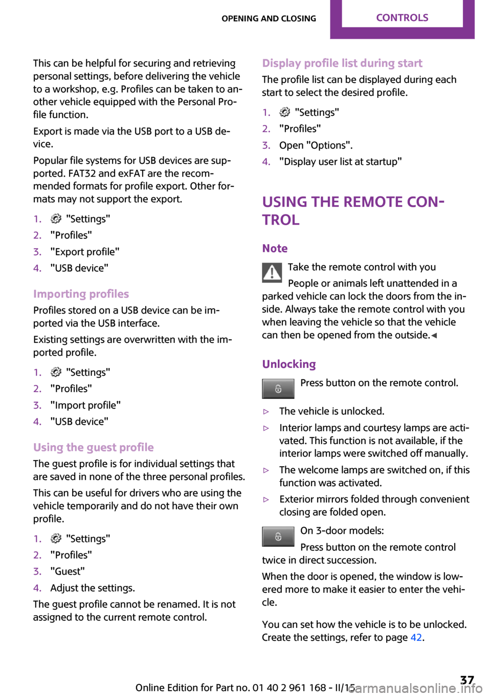
Unlocking Press button on the remote control.
▷The vehicle is unlocked.▷Interior lamps and courtesy lamps are acti‐
vated. This function is not available, if the
interior lamps were switched off manually.▷The welcome lamps are switched on, if this
function was activated.▷Exterior mirrors folded through convenient
closing are folded open.
On 3-door models:
Press button on the remote control
twice in direct succession.
When the door is opened, the window is low‐
ered more to make it easier to enter the vehi‐
cle.
You can set how the vehicle is to be unlocked.
Create the settings, refer to page 42.
Seite 37Opening and closingCONTROLS37
Online Edition for Part no. 01 40 2 961 168 - II/15
Page 44 of 244

From the inside
Locking and unlocking
Press button.
Vehicle is locked.
Press button.
The vehicle is unlocked.
Pressing the buttons for the central locking sys‐
tem locks and unlocks the doors and the tail‐
gate when the front doors are closed, but they
are not secured against theft.
The fuel filler flap remains unlocked.
In the event of a severe accident, the vehicle is
automatically unlocked. The hazard warning
system and interior lights come on.
Unlocking and opening
Either unlock the doors together using the cen‐
tral locking system buttons and then pull the
door handle above the armrest or pull the door
handle on the door to open the door. The other
doors remain locked.
TailgateHints Keep the closing path clear
Make sure that the closing path of the
tailgate is clear; otherwise, injuries may result. ◀
Do not place the remote control in the
cargo area
Take the remote control with you and do not
leave it in the cargo area; otherwise, the re‐
mote control is locked inside the vehicle when
the tailgate is closed. ◀
Provide edge protection
Sharp objects or those with edges can hit
the rear window while driving and damage the
heat conductors of the rear window. Provide
edge protection. ◀
Opening
When the tailgate is opened, make sure there is
sufficient clearance to prevent damage.▷Unlock the vehicle and press the button on
the tailgate.▷Press button on the remote control
for approx. 1 second.
As the case may be, the doors are also un‐
locked. Unlocking with the remote control,
refer to page 38.
The tailgate is unlocked and can be swung up‐
ward.
Opening from the inside With the vehicle is stationary, press the
button in the driver's footwell.
Seite 40CONTROLSOpening and closing40
Online Edition for Part no. 01 40 2 961 168 - II/15
Page 46 of 244

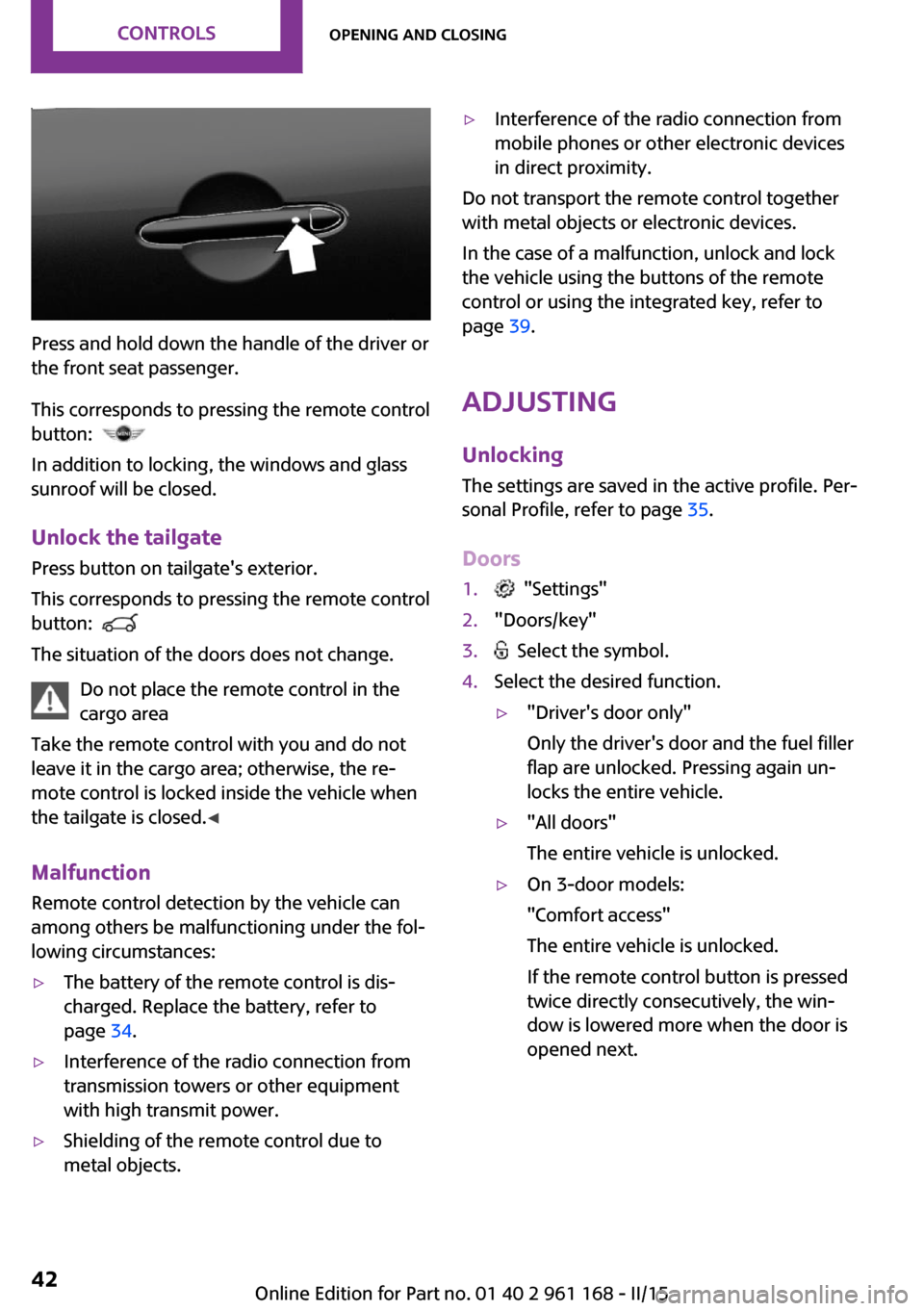
Press and hold down the handle of the driver or
the front seat passenger.
This corresponds to pressing the remote control
button:
In addition to locking, the windows and glass
sunroof will be closed.
Unlock the tailgate Press button on tailgate's exterior.
This corresponds to pressing the remote control
button:
The situation of the doors does not change.
Do not place the remote control in the
cargo area
Take the remote control with you and do not
leave it in the cargo area; otherwise, the re‐
mote control is locked inside the vehicle when
the tailgate is closed. ◀
Malfunction Remote control detection by the vehicle can
among others be malfunctioning under the fol‐
lowing circumstances:
▷The battery of the remote control is dis‐
charged. Replace the battery, refer to
page 34.▷Interference of the radio connection from
transmission towers or other equipment
with high transmit power.▷Shielding of the remote control due to
metal objects.▷Interference of the radio connection from
mobile phones or other electronic devices
in direct proximity.
Do not transport the remote control together
with metal objects or electronic devices.
In the case of a malfunction, unlock and lock
the vehicle using the buttons of the remote
control or using the integrated key, refer to
page 39.
Adjusting Unlocking The settings are saved in the active profile. Per‐
sonal Profile, refer to page 35.
Doors
1. "Settings"2."Doors/key"3. Select the symbol.4.Select the desired function.▷"Driver's door only"
Only the driver's door and the fuel filler
flap are unlocked. Pressing again un‐
locks the entire vehicle.▷"All doors"
The entire vehicle is unlocked.▷On 3-door models:
"Comfort access"
The entire vehicle is unlocked.
If the remote control button is pressed
twice directly consecutively, the win‐
dow is lowered more when the door is
opened next.Seite 42CONTROLSOpening and closing42
Online Edition for Part no. 01 40 2 961 168 - II/15
Page 60 of 244

Transporting children safelyVehicle features and op‐
tions
This chapter describes all standard, country-
specific and optional features offered with the
series. It also describes features that are notnecessarily available in your car, e. g., due to
the selected options or country versions. This
also applies to safety-related functions and sys‐
tems. The respectively applicable country provi‐
sions must be observed when using the respec‐
tive features and systems.
The right place for children
Note
Children in the vehicle
Do not leave children unattended in the
vehicle; otherwise, they could endanger them‐
selves and other persons, e.g., by opening the
doors. ◀
Children should always be in the rear Accident research shows that the safest place
for children is in the back seat.
Transporting children in the rear
Only transport children younger than
13 years of age or shorter than 5 ft/150 cm in
the rear in child restraint systems provided in
accordance with the age, weight and size of
the child; otherwise, there is an increased risk
of injury in an accident.
Children 13 years of age or older must wear a
safety belt as soon as a suitable child restraint system can no longer be used due to their age,
weight and size. ◀
Children on the front passenger seat
Should it ever be necessary to use a child re‐
straint system in the front passenger seat,
make sure that the front, knee and side airbags
on the front passenger side are deactivated.
Automatic deactivation of front-seat passenger
airbags, refer to page 97.Note
Deactivating the front-seat passenger air‐
bags
If a child restraint system is used in the front
passenger seat, deactivate the front-seat pas‐
senger airbags; otherwise, there is an increased
risk of injury to the child when the airbags are
activated, even with a child restraint system. ◀
Installing child re‐
straint systems
Hints Manufacturer's information for child re‐straint systems
To select, mount and use child restraint sys‐
tems, observe the information provided by the
system manufacturer; otherwise, the protective
effect can be lost. ◀
Ensuring the stability of the child seat
When installing child restraint systems,
make sure that the child seat is securely fas‐
tened to the backrest of the seat. Angle and
headrest of the backrest might need to be ad‐
justed or possibly be removed. Make sure that
all backrests are securely locked. Otherwise the
stability of the child seat can be affected, andSeite 56CONTROLSTransporting children safely56
Online Edition for Part no. 01 40 2 961 168 - II/15
Page 61 of 244

there is an increased risk of injury because of
unexpected movement of the seat backrest. ◀
In order to faciliate the installation of a back-
facing child restraint system in the rear:
move the front passenger's seat as far up as
possible before folding down the backrest.
On the front passenger seat
Deactivating airbags
After installing a child restraint system in the
front passenger seat, make sure that the front,
knee and side airbags on the front passenger
side are deactivated.
Deactivate the front-seat passenger airbags au‐
tomatically, refer to page 97.
Deactivating the front-seat passenger air‐
bags
If a child restraint system is used in the front
passenger seat, deactivate the front-seat pas‐
senger airbags; otherwise, there is an increased
risk of injury to the child when the airbags are
activated, even with a child restraint system. ◀
Seat position and height
Before installing a child restraint system, move
the front passenger seat as far back as possible
and adjust its height to the highest and thus
best possible position for the belt and to offer
optimal protection in the event of an accident.
If the upper anchorage of the safety belt is lo‐
cated in front of the belt guide of the child seat,move the passenger seat carefully forward until
the best possible belt guide position is reached.
Child seat security
The rear safety belts and the front passenger
safety belt can be permanently locked to fasten
child restraint systems.
Locking the safety belt
1.Pull out the strap completely.2.Secure the child restraint system with the
belt.3.Allow the strap to be pulled in and pull it
tight against the child restraint system. The
safety belt is locked.
Unlocking the safety belt
1.Unbuckle the belt buckle.2.Remove the child restraint system.3.Allow the strap to be pulled in completely.
LATCH child restraint system
LATCH: Lower Anchors and Tether for Children.
Note Follow manufacturer's information for
LATCH child restraint systems
To mount and use the LATCH child restraint sys‐
tems, observe the operating and safety infor‐mation from the system manufacturer; other‐
wise, the level of protection may be reduced. ◀
Mounts for the lower LATCH anchors
The lower anchors may be used to attach the
CRS to the vehicle seat up to a combined childSeite 57Transporting children safelyCONTROLS57
Online Edition for Part no. 01 40 2 961 168 - II/15
Page 62 of 244

and CRS weight of 65 lb when the child is re‐
strained by the internal harnesses.
Properly engage the lower LATCH an‐chors
Make sure that the lower LATCH anchors have
properly engaged and that the child restraint
system is resting snugly against the backrest;
otherwise, the degree of protection may be re‐
duced. ◀
Before mounting the LATCH child restraint sys‐
tem, pull the belt away from the child restraint
system.
Position The corresponding symbol shows the
mounts for the lower LATCH anchors.
Seats equipped with lower anchors are
marked with a pair, 2, of LATCH sym‐
bols. It is not recommended to use the
inner lower anchors of standard outer LATCH
positions to fasten a child restraint system on
the middle seat. Use the vehicle seat belt in‐
stead for the middle seat.
Assembly of LATCH child restraint
systems1.Mount the child restraint system; refer to
the user's manual of the system.2.Ensure that both LATCH anchors are prop‐
erly connected.
Child restraint fixing system with a
tether strap
Note Mounting eyelets
Use the mounting eyes only for the upper
retaining strap to secure child restraint systems;
otherwise, the mounting eyes could be dam‐
aged. ◀
Mounting points
The respective symbol shows the an‐chor for the upper retaining strap. Seats
with an upper Top Tether are marked
with this symbol. It can be found on the rear
seat backrest or the rear window shelf.
Retaining strap guide Retaining strap
Make sure that the upper retaining strap
is not passed over the head restraints or sharp
edges and is not twisted up to the upper
mounting points; otherwise, the belt cannot
properly secure the child restraint system in an
accident. ◀1Direction of travel2Head restraint3Hook for upper retaining strap4Mounting point/eye5Seat backrest6Upper retaining strap
Attaching the upper retaining strap to
the mounting point
1.Raise the head restraint if needed.2.Guide the upper retaining strap between
the supports of the head restraint.3.Attach the hook of the retaining strap to
the mounting eye on the rear seat.4.Tighten the retaining strap by pulling it
down.Seite 58CONTROLSTransporting children safely58
Online Edition for Part no. 01 40 2 961 168 - II/15
Page 63 of 244

No persons on the back seat when there
is a child restraint system with an upper
retaining strap on the front passenger seat.
When there is a child restraint system with an
upper retaining strap on the front passenger
seat, no one should sit in the back seat directly
behind it, otherwise there is an increased risk of
injury due to the upper retaining strap. ◀
Upper retaining strap when the backrest
is folded down
When the backrest is folded down, do not
guide the belt through the head restraint sup‐
ports on the backrest; otherwise the belt may
not secure the child restraint system properly in
case of an accident ◀
ON 5-door models: Lock‐
ing the doors and win‐
dows
Rear doors
Push the locking lever on the rear doors up.
The door can now be opened from the outside
only.
Safety switch for the rear Press button on the driver's door if
children are being transported in the
rear.
This locks various functions so that they cannot
be operated from the rear: safety switch, refer
to page 46.Seite 59Transporting children safelyCONTROLS59
Online Edition for Part no. 01 40 2 961 168 - II/15
Page 65 of 244

▷After approx. 8 minutes.▷When the vehicle is locked using the central
locking system.▷Shortly before the battery is discharged
completely, so that the engine can still be
started.
The radio-ready state remains active if, e.g., the
ignition is automatically switched off for the fol‐
lowing reasons:
▷Opening or closing the driver's door.▷Unfastening of the driver's safety belt.▷When automatically switching from low
beams to parking lights.
If the engine is switched off and the ignition is
switched on, the system automatically switches
to the radio-ready state if the lights are turned
off or, if correspondingly equipped, the day‐
time running lights are activated.
Starting the engine
Hints Enclosed areas
Do not let the engine run in enclosed
areas, since breathing in exhaust fumes may
lead to loss of consciousness and death. The
exhaust gases contain carbon monoxide, an
odorless and colorless but highly toxic gas. ◀
Unattended vehicle
Do not leave the vehicle unattended with
the engine running; doing so poses a risk of
danger.
Before leaving the vehicle with the engine run‐
ning, set the parking brake and place the trans‐
mission in selector lever position P or N to pre‐
vent the vehicle from moving. ◀
Repeated starting in quick succession
Avoid trying to start the vehicle repeat‐
edly and in quick succession. Otherwise, the
fuel is not burned or is inadequately burned,
posing a risk of overheating and damage to the
catalytic converter. ◀
Do not wait for the engine to warm-up while
the vehicle remains stationary. Start driving at
moderate engine speeds.
Steptronic transmission
Starting the engine1.Depress the brake pedal.2.Engage selector lever position P or N.3.Press the Start/Stop button.
The ignition is activated automatically for a cer‐
tain time and is stopped as soon as the engine
starts.
Manual transmission
Starting the engine
1.Depress the brake pedal.2.Press on the clutch pedal and shift to neu‐
tral.3.Press the Start/Stop button.
The ignition is activated automatically for a cer‐
tain time and is stopped as soon as the engine
starts.
Engine stop
Hints Take the remote control with you
Take the remote control with you when
leaving the vehicle so that children, e.g., cannot
start the engine. ◀
Apply parking brake and further secure
the vehicle if needed.
Set the parking brake firmly when parking; oth‐
erwise, the vehicle could roll. On steep upward
and downward inclines, further secure the ve‐
Seite 61DrivingCONTROLS61
Online Edition for Part no. 01 40 2 961 168 - II/15