ECU MINI Hardtop 4 Door 2016 User Guide
[x] Cancel search | Manufacturer: MINI, Model Year: 2016, Model line: Hardtop 4 Door, Model: MINI Hardtop 4 Door 2016Pages: 251, PDF Size: 6.71 MB
Page 82 of 251

Ejection MitigationThe head airbag system is designed as an ejec‐
tion mitigation countermeasure to reduce the
likelihood of ejections of vehicle occupants
through side windows during rollovers or side
impact events.
Knee airbag
The knee airbag supports the legs in a frontal
impact.
Protective action
Airbags are not triggered in every impact situa‐
tion, e.g., in less severe accidents or rear-end
collisions.
Information for optimum effect of the
airbags
WARNING
If the seat position is incorrect or the de‐
ployment area of the airbags is impacted, the
airbag system cannot protect as intended or
cause additional injuries due to triggering.
There is risk of injuries or danger to life. Ob‐
serve the Information for optimum protective
effect of the airbag system. ◀▷Keep at a distance from the airbags.▷Make sure that occupants keep their heads
away from the side airbag.▷Always grasp the steering wheel on the
steering wheel rim. Hold your hands at the
3 o'clock and 9 o'clock positions, to keep
the risk of injury to your hands or arms as
low as possible when the airbag is trig‐
gered.▷Make sure that the front passenger is sitting
correctly, i.e., keeps his or her feet and legs
in the floor area.▷There should be no persons, animals or ob‐
jects between an airbag and a person.▷Do not apply adhesive materials to the air‐
bag cover panels, do not cover them or
modify them in any way.▷Dashboard and windshield on the front
passenger side must stay clear - do not at‐
tach adhesive labels or coverings and do
not attach brackets or cables, e. g., for GPS
devices or' mobile phones.▷Do not use the cover of the front airbag on
the front passenger side as a storage area.▷Do not place slip covers, seat cushions or
other objects on the front passenger seat
that are not specifically suited for seats with
integrated side airbags.▷Do not hang pieces of clothing, such as
jackets, over the backrests.▷Never modify either the individual compo‐
nents or the wiring in the airbag system.
This also applies to steering wheel covers,
the dashboard, and the seats.▷Do not remove the airbag system.
Even when you follow all instructions very
closely, injury from contact with the airbags
cannot be ruled out in certain situations.
The ignition and inflation noise may lead to
short-term and, in most cases, temporary hear‐
ing impairment in sensitive individuals.
Warnings and information on the airbags are
also found on the sun visors.
Functional readiness of the airbag
system
Information WARNING
Individual components can be hot after
triggering of the airbag system. There is risk of
injuries. Do not touch individual components. ◀
WARNING
Improperly executed work can lead to
failure, malfunction or unintentional triggering
of the airbag system. In the case of a malfunc‐
Seite 82CONTROLSSafety82
Online Edition for Part no. 01 40 2 963 307 - VI/15
Page 93 of 251

PrewarningThis warning is issued, e.g., when there is the
impending danger of a collision or the distance
to the vehicle ahead is too small.
The driver must intervene actively when there
is a prewarning.
Acute warning with braking function
Acute warning in displayed in case of the immi‐
nent danger of a collision when the vehicle ap‐
proaches another object at a relatively high dif‐
ferential speed.
The driver must intervene actively when there
is an acute warning. If necessary, the driver is
assisted by a minor automatic braking inter‐
vention in a possible risk of collision.
Acute warnings can also be triggered without
previous forewarning.
Braking intervention The warning prompts the driver himself/herself
to react. During a warning, the maximum brak‐
ing force is used. Premise for the brake booster
is sufficiently quick and sufficiently hard step‐
ping on the brake pedal. The system can assist
with some braking intervention if there is risk of
a collision. At low speeds vehicles may thus
come to a complete stop.
Manual transmission: During a braking inter‐
vention up to a complete stop, the engine may
be shut down.
The braking intervention is executed only if DSC
Dynamic Stability Control is switched on.
The braking intervention can be interrupted by
stepping on the accelerator pedal or by actively
moving the steering wheel.
Object detection can be restricted. Limitations
of the detection range and functional restric‐
tions are to be considered.System limits
Detection range The system's detection potential is limited.
Thus a system reaction might not come or
might come late.
E. g. the following situations may not be de‐ tected:▷Slow moving vehicles when you approach
them at high speed.▷Vehicles that suddenly swerve in front of
you, or sharply decelerating vehicles.▷Vehicles with an unusual rear appearance.▷Two-wheeled vehicles ahead of you.
Functional limitations
The system may not be fully functional in the
following situations:
▷In heavy fog, rain, sprayed water or snow‐
fall.▷In tight curves.▷If the field of view of the camera or the
front windshield are dirty or covered.▷If the driving stability control systems are
deactivated, e.g. DSC OFF.▷Up to 10 seconds after the start of the en‐
gine, via the Start/Stop button.▷During calibration of the camera immedi‐
ately after vehicle delivery.▷If there are constant blinding effects be‐
cause of oncoming light, e. g., from the sun
low in the sky.
Warning sensitivity
The more sensitive the warning settings are,
the more warnings are displayed. However,
there may also be an excess of false warnings.
Seite 93SafetyCONTROLS93
Online Edition for Part no. 01 40 2 963 307 - VI/15
Page 95 of 251

Camera
The camera is installed near the interior rear‐
view mirror.
Keep the windshield in the area behind the in‐
terior rearview mirror clean and clear.
Switching on/off
Switching on automatically
The system is automatically active after every
driving-off.
Switching on/off manually Press button briefly:
▷The menu for the intelligent safety
system is displayed. The systems
are individually switched off ac‐
cording to their respective settings.▷LED lights up orange or goes out respective
to their individual settings.
Adjust as needed. Individual settings are stored
for the profile currently used.
Press button again:
▷All Intelligent Safety systems are
activated.▷The LED lights up green.
Hold down button:
▷All Intelligent Safety systems are
turned off.▷The LED goes out.Warning with braking function
Display
If a collision with a person detected in this way
is imminent, a warning symbol appears on the
instrument cluster.
The red symbol is displayed and a signal
sounds.
Intervene immediately by braking or
make an evasive maneuver.
Braking intervention
The warning prompts the driver himself/herself
to react. During a warning, the maximum brak‐
ing force is used. Premise for the brake booster
is sufficiently quick and sufficiently hard step‐
ping on the brake pedal. The system can assist
with some braking intervention if there is risk of
a collision. At low speeds vehicles may thus come to a complete stop.
Manual transmission: During a braking inter‐
vention up to a complete stop, the engine may
be shut down.
The braking intervention is executed only if DSC
Dynamic Stability Control is switched on.
The braking intervention can be interrupted by
stepping on the accelerator pedal or by actively
moving the steering wheel.
Object detection can be restricted. Limitations
of the detection range and functional restric‐
tions are to be considered.
System limits
Detection range The detection potential of the camera is lim‐
ited.
Thus a warning might not be issued or be is‐
sued late.
E. g. the following situations may not be de‐
tected:▷Partially covered pedestrians.Seite 95SafetyCONTROLS95
Online Edition for Part no. 01 40 2 963 307 - VI/15
Page 96 of 251

▷Pedestrians that are not detected as such
because of the viewing angle or contour.▷Pedestrians outside of the detection range.▷Pedestrians having a body size less than
32 in/80 cm.
Functional limitations
The system may not be fully functional or may
not be available in the following situations:
▷In heavy fog, rain, sprayed water or snow‐
fall.▷In tight curves.▷If the field of view of the camera or the
front windshield are dirty or covered.▷If the driving stability control systems are
deactivated, e.g. DSC OFF.▷Up to 10 seconds after the start of the en‐
gine, via the Start/Stop button.▷During calibration of the camera immedi‐
ately after vehicle delivery.▷If there are constant blinding effects be‐
cause of oncoming light, e. g., from the sun
low in the sky.▷When it is dark outside.
Brake force display
The concept
▷During normal brake application, the brake
lights light up.▷During heavy brake application, the flash‐
ers light up in addition.
PostCrash
In the event of an accident, the system can
bring the car to a halt automatically without in‐
tervention by the driver in certain situations.
This can reduce the risk of a further collision
and the consequences thereof.
Depressing the brake pedal can cause the vehi‐
cle to brake harder. This interrupts automatic
braking. Destepping on the gas pedal also in‐
terrupts automatic braking.
After coming to a halt, the brake is released au‐
tomatically. Secure the vehicle against rolling.
Seite 96CONTROLSSafety96
Online Edition for Part no. 01 40 2 963 307 - VI/15
Page 121 of 251

Interior equipmentVehicle features and op‐
tions
This chapter describes all standard, country-
specific and optional features offered with the
series. It also describes features that are not
necessarily available in your car, e. g., due to
the selected options or country versions. This
also applies to safety-related functions and sys‐
tems. The respectively applicable country provi‐
sions must be observed when using the respec‐
tive features and systems.
Universal Integrated Re‐
mote Control
The concept
The Universal Integrated Remote Control can
operate up to 3 functions of remote-controlled
systems such as garage door drives or lighting
systems. The Universal Integrated Remote Con‐
trol replaces up to 3 different hand-held trans‐
mitters. To operate the remote control, the but‐
tons on the interior rearview mirror must be
programmed with the desired functions. The
hand-held transmitter for the particular system
is required in order to program the remote con‐
trol.
Before selling the vehicle, delete the stored
functions for the sake of security.
Information WARNING
Body parts can be jammed when operat‐
ing remote-controlled systems, e.g. the garage
door, using the universal garage door opener.
There is risk of injuries or risk of property dam‐
age. Make sure that the area of movement of
the respective system is clear during program‐ming and operation. Also follow the safety in‐
structions of the hand-held transmitter. ◀
Compatibility If this symbol is printed on the packag‐
ing or in the instructions of the system
to be controlled, the system is generally
compatible with the Universal Integrated Re‐
mote Control.
If you have any questions, please contact:▷A dealer’s service center or another quali‐
fied service center or repair shop.▷www.homelink.com on the Internet.
HomeLink is a registered trademark of Gentex
Corporation.
Overview
1LED2Programmable keys3Hand-held transmitters of the system
Programming
General information
1.Switch on the ignition.2.Initial setup:
Press and hold the left and right button on
the interior rearview mirror simultaneously
for approximately 20 seconds until the LEDSeite 121Interior equipmentCONTROLS121
Online Edition for Part no. 01 40 2 963 307 - VI/15
Page 126 of 251

devices and cables are not in the airbag's area
of unfolding. ◀
Sockets Sockets can be used for the running electrical
devices with the engine running or with the ig‐
nition switched on. The total load of all sockets
must not exceed 140 watts at 12 volts.
Do not damage the socket by using non-com‐
patible connectors.
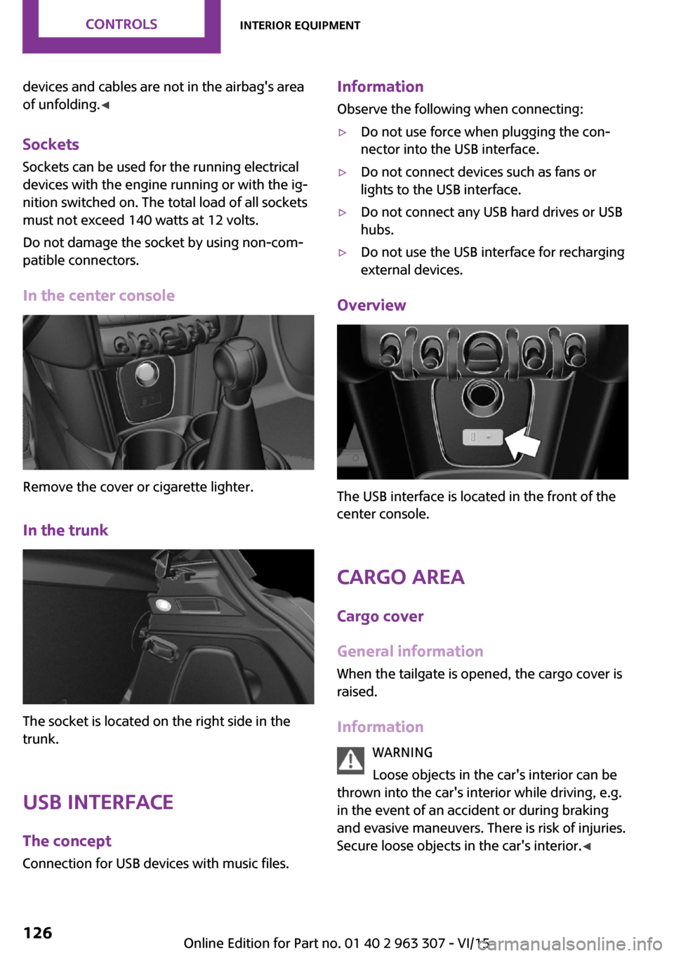
In the center console
Remove the cover or cigarette lighter.
In the trunk
The socket is located on the right side in the
trunk.
USB interface
The concept
Connection for USB devices with music files.
Information Observe the following when connecting:▷Do not use force when plugging the con‐
nector into the USB interface.▷Do not connect devices such as fans or
lights to the USB interface.▷Do not connect any USB hard drives or USB
hubs.▷Do not use the USB interface for recharging
external devices.
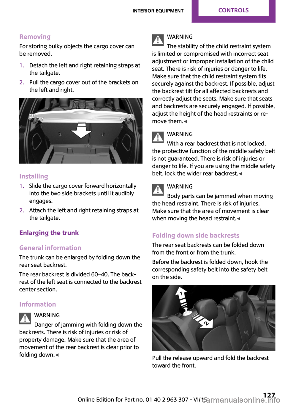
Overview
The USB interface is located in the front of the
center console.
Cargo area
Cargo cover
General information When the tailgate is opened, the cargo cover is
raised.
Information WARNING
Loose objects in the car's interior can be
thrown into the car's interior while driving, e.g.
in the event of an accident or during braking
and evasive maneuvers. There is risk of injuries.
Secure loose objects in the car's interior. ◀
Seite 126CONTROLSInterior equipment126
Online Edition for Part no. 01 40 2 963 307 - VI/15
Page 127 of 251

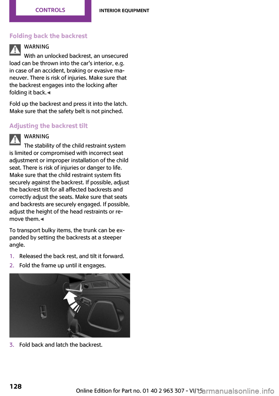
Removing
For storing bulky objects the cargo cover can be removed.1.Detach the left and right retaining straps at
the tailgate.2.Pull the cargo cover out of the brackets on
the left and right.
Installing
1.Slide the cargo cover forward horizontally
into the two side brackets until it audibly
engages.2.Attach the left and right retaining straps at
the tailgate.
Enlarging the trunk
General information
The trunk can be enlarged by folding down the
rear seat backrest.
The rear backrest is divided 60–40. The back‐
rest of the left seat is connected to the backrest
center section.
Information WARNING
Danger of jamming with folding down the
backrests. There is risk of injuries or risk of property damage. Make sure that the area of
movement of the rear backrest is clear prior to
folding down. ◀
WARNING
The stability of the child restraint system
is limited or compromised with incorrect seat
adjustment or improper installation of the child
seat. There is risk of injuries or danger to life.
Make sure that the child restraint system fits
securely against the backrest. If possible, adjust
the backrest tilt for all affected backrests and
correctly adjust the seats. Make sure that seats
and backrests are securely engaged. If possible,
adjust the height of the head restraints or re‐
move them. ◀
WARNING
With a rear backrest that is not locked,
the protective function of the middle safety belt
is not guaranteed. There is risk of injuries or
danger to life. If you are using the middle safety
belt, lock the wider rear backrest. ◀
WARNING
Body parts can be jammed when moving
the head restraint. There is risk of injuries.
Make sure that the area of movement is clear
when moving the head restraint. ◀
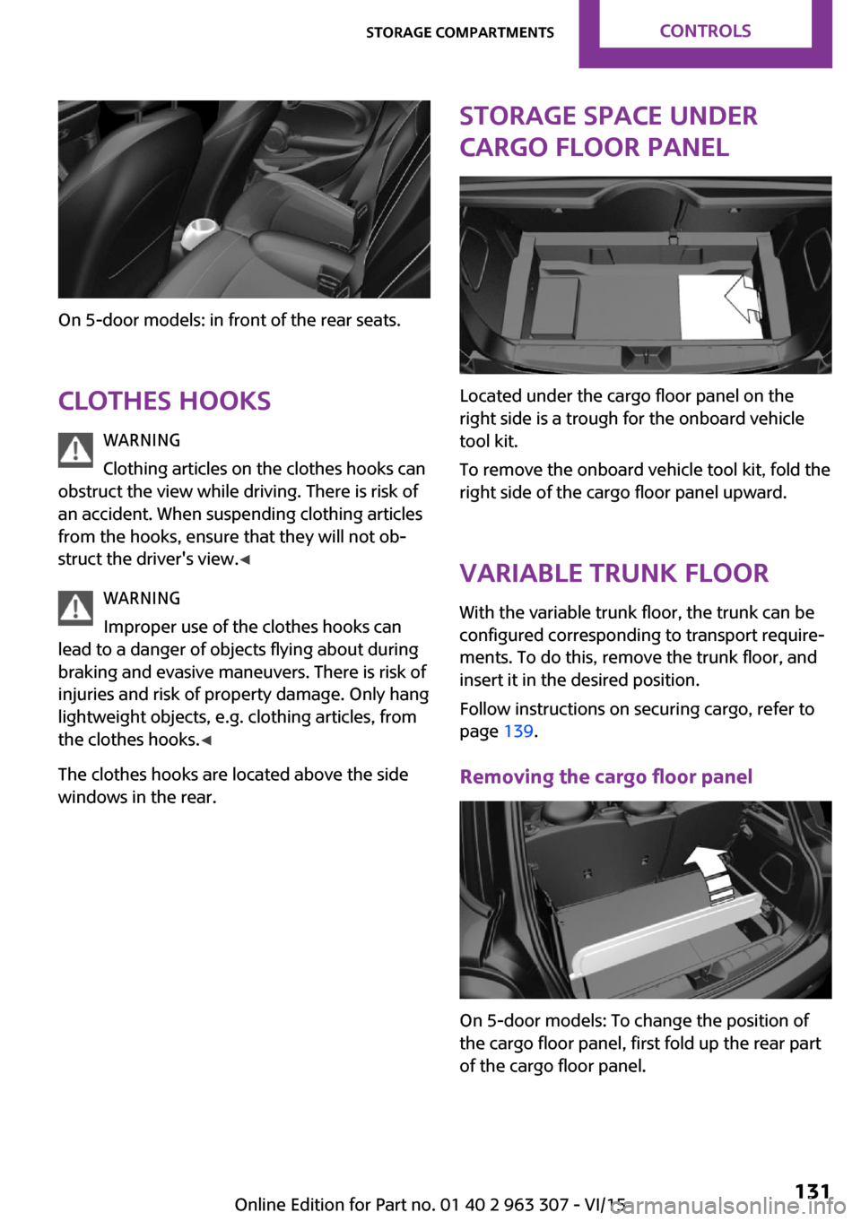
Folding down side backrests
The rear seat backrests can be folded down
from the front or from the trunk.
Before the backrest is folded down, hook the
corresponding safety belt into the safety belt
on the side.
Pull the release upward and fold the backrest
toward the front.
Seite 127Interior equipmentCONTROLS127
Online Edition for Part no. 01 40 2 963 307 - VI/15
Page 128 of 251

Folding back the backrestWARNING
With an unlocked backrest, an unsecured
load can be thrown into the car's interior, e.g.
in case of an accident, braking or evasive ma‐
neuver. There is risk of injuries. Make sure that
the backrest engages into the locking after
folding it back. ◀
Fold up the backrest and press it into the latch.
Make sure that the safety belt is not pinched.
Adjusting the backrest tilt WARNING
The stability of the child restraint system
is limited or compromised with incorrect seat
adjustment or improper installation of the child
seat. There is risk of injuries or danger to life.
Make sure that the child restraint system fits
securely against the backrest. If possible, adjust
the backrest tilt for all affected backrests and
correctly adjust the seats. Make sure that seats
and backrests are securely engaged. If possible,
adjust the height of the head restraints or re‐
move them. ◀
To transport bulky items, the trunk can be ex‐
panded by setting the backrests at a steeper
angle.1.Released the back rest, and tilt it forward.2.Fold the frame up until it engages.3.Fold back and latch the backrest.Seite 128CONTROLSInterior equipment128
Online Edition for Part no. 01 40 2 963 307 - VI/15
Page 129 of 251

Storage compartmentsVehicle features and op‐
tions
This chapter describes all standard, country-
specific and optional features offered with the
series. It also describes features that are not necessarily available in your car, e. g., due to
the selected options or country versions. This
also applies to safety-related functions and sys‐
tems. The respectively applicable country provi‐
sions must be observed when using the respec‐
tive features and systems.
Information WARNING
Loose objects in the car's interior can be
thrown into the car's interior while driving, e.g.
in the event of an accident or during braking
and evasive maneuvers. There is risk of injuries.
Secure loose objects in the car's interior. ◀
CAUTION
Anti-slip pads such as anti-slip mats can
damage the dashboard. There is risk of prop‐
erty damage. Do not use anti-slip pads. ◀
Overview
The following storage compartments are avail‐
able in the vehicle interior:▷Storage compartment in front of the cu‐
pholders.▷Storage tray in the center console.▷Glove compartment on the front passenger
side.▷Storage compartment in the center arm‐
rest.▷Compartments in the doors.▷Pockets on the backrests of the front seats.
Glove compartment
Information WARNING
Folded open, the glove compartment
protrudes in the car's interior. Objects in the
glove compartment can be thrown into the
car's interior while driving, e.g. in the event of
an accident or during braking and evasive ma‐
neuvers. There is risk of injuries. Always close
the glove compartment immediately after us‐
ing it. ◀
Opening
Pull the handle.
The light in the glove compartment switches
on.
Closing Fold up the cover.
Seite 129Storage compartmentsCONTROLS129
Online Edition for Part no. 01 40 2 963 307 - VI/15
Page 131 of 251

On 5-door models: in front of the rear seats.
Clothes hooks WARNING
Clothing articles on the clothes hooks can
obstruct the view while driving. There is risk of
an accident. When suspending clothing articles
from the hooks, ensure that they will not ob‐
struct the driver's view. ◀
WARNING
Improper use of the clothes hooks can
lead to a danger of objects flying about during
braking and evasive maneuvers. There is risk of
injuries and risk of property damage. Only hang
lightweight objects, e.g. clothing articles, from
the clothes hooks. ◀
The clothes hooks are located above the side
windows in the rear.
Storage space under
cargo floor panel
Located under the cargo floor panel on the
right side is a trough for the onboard vehicle
tool kit.
To remove the onboard vehicle tool kit, fold the
right side of the cargo floor panel upward.
Variable trunk floor
With the variable trunk floor, the trunk can be
configured corresponding to transport require‐
ments. To do this, remove the trunk floor, and
insert it in the desired position.
Follow instructions on securing cargo, refer to
page 139.
Removing the cargo floor panel
On 5-door models: To change the position of
the cargo floor panel, first fold up the rear part
of the cargo floor panel.
Seite 131Storage compartmentsCONTROLS131
Online Edition for Part no. 01 40 2 963 307 - VI/15